1. Preface
This article discusses the impact of surface carbon concentration on the heat treatment properties of 20CrMo steel.
To ensure the desired carbon content in the furnace atmosphere throughout the carburizing process and the required surface carbon concentration of the workpiece after carburization, the carbon concentration in the carburizing process must be meticulously regulated. In addition, optimizing the quenching process can help attain better quenching hardness, resulting in good wear resistance.
20CrMo steel is a low-alloy carbon structural steel extensively used in producing a variety of workpieces, such as gears, shafts, and high-strength fasteners. For instance, in a company’s production, this material is utilized in constructing the hydraulic cylinder of the hydraulic crusher on the construction machinery.
For the hydraulic cylinder to meet the required high hardness and wear resistance post-carburizing heat treatment, as well as good plasticity and toughness (i.e., excellent comprehensive mechanical properties), targeted research was necessary.
However, during the initial production of the hydraulic cylinder, the surface hardness of the workpiece was low, and this issue persisted despite efforts to rectify it by adjusting the process conditions. As a result, a focused study was conducted on the workpiece.
2. Heat treatment process, technical requirements and problems of hydraulic cylinder
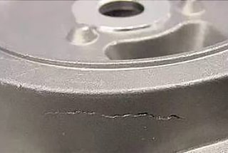
This hydraulic cylinder type has a large volume, with a unit weight of approximately 365kg and an effective thickness of 150-200mm.
Please refer to Figure 1 for a visual representation of the actual workpiece.

After undergoing heat treatment, carburization, and quenching, the workpiece should have a carburizing layer depth of 1.0-1.4mm and an overall hardness of 58-62HRC.
Please refer to Table 1 for the chemical composition specifications of 20CrMo steel in GB/T 3077-1999 alloy structural steel.
Table 1 chemical composition of 20CrMo steel (mass fraction) (%)
| C | Mn | Si | Cr | Mo | P | S |
| 0.17~0.24 | 0.4~0.7 | 0.17~0.37 | 0.80~1.10 | 0.15~0.25 | ≤0.035 | ≤0.035 |
Various process methods are utilized for treatment during actual production. However, the results indicate that the surface hardness is below 50HRC, rendering it unqualified. Adjusting the carburizing temperature and increasing the quenching temperature cannot fulfill the technical requirements.
For specific details regarding the heat treatment process, please refer to Table 2.
Table 2 heat treatment process
| NO. | Process parameters | Workpiece surface hardness (HRC) |
| 1 | Strong permeability: 920 ℃ × 330min, carbon potential 1.1%; Diffusion: 920 ℃ x130min, carbon potential 0.85%; Quenching insulation: 830 ℃ × 30min, carbon potential 0.85%. | 45~47 |
| 2 | Strong permeability: 920 ℃ × 350min, carbon potential 1.1%; Diffusion: 920 ℃ × 140min, carbon potential 0.9%; Quenching and heat preservation: 840 ℃ x30min, carbon potential 0.9%. | 46~47 |
| 3 | Strong permeability: 930 ℃ × 330min, carbon potential 1.2%; Diffusion: 930 ℃ x 30min, carbon potential 0.9%; Quenching insulation: 860 ℃ × 40 min, carbon potential 0.9%. | 49~50 |
| 4 | Strong penetration: 930 ℃ x450min, carbon potential 1.2%; Diffusion: 930 ℃ × 250min, carbon potential 0.9%; Quenching and heat preservation: 860 ℃ x30min, carbon potential 0.9%. | 46~48 |
3. Cause analysis of low surface hardness of hydraulic cylinder
(1) Carburizing temperature
The carburizing temperature is a crucial technological parameter in the carburizing process, and it significantly affects the ability of austenite to dissolve carbon.
As the temperature increases, the solubility of carbon in austenite also increases.
According to the iron-carbon phase diagram, the saturated solubility of carbon in austenite is 1.0% at 850℃ and 1.25% at 930℃.
The accuracy of the carburizing temperature directly affects the quenching quality of the workpiece.
After performing a 9-point temperature detection of the equipment, we have found no deviation in the temperature, the furnace temperature is normal, and no significant temperature difference is present.
Therefore, we can exclude the influence of temperature on the surface hardness of the workpiece.
(2) Effect of carbon concentration
During the process execution, a furnace test block measuring 25mm x 25mm is used for each process number.
The hardness test results of the test block are better than those of the workpiece body.
Please refer to Table 3 for the hardness test results of the carburized test block executed according to process 3, both in the end face and longitudinal direction of the workpiece.
Table 3 workpiece hardness test results (HRC)
|
Surface |
Core |
|||||
|
End face |
59 |
60 |
58.5 |
59.6 |
20 |
21 |
|
Portrait |
56.6 |
57.5 |
55.2 |
56 |
||
As per the hardness method specified in GB/T 9450-2005 for determining and verifying the effective hardened layer depth of carburizing and quenching of iron and steel, the hardness gradient of the carburizing layer is tested on the furnace test block after the heat treatment process.
The results are shown in Table 4.
Table 4 hardness gradient test results of workpiece penetration layer
| Carburizing layer depth / mm | Hardness HV1 |
| 0.1 | 622.9 |
| 0.2 | 747.7 |
| 0.3 | 714.4 |
| 0.4 | 720 |
| 0.5 | 685.8 |
| 0.6 | 662.7 |
| 0.7 | 635.9 |
| 0.8 | 635.9 |
| 0.9 | 599.9 |
| 1 | 568.8 |
| 1.1 | 540 |
The carburized layer of the test block is examined using the metallographic analysis method to verify whether the carbon concentration meets the required specifications.
Figure 2 illustrates the metallographic structure of the surface layer and the effective depth of the hardened layer of the workpiece.
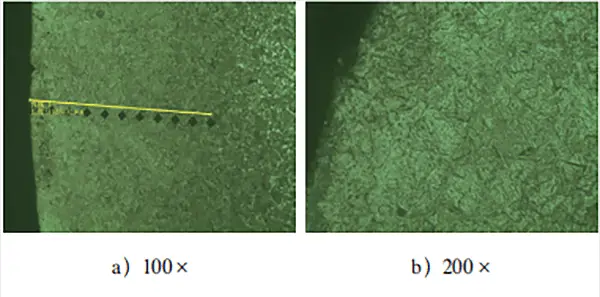
After observing the metallographic structure of the test block’s carburized layer in Fig. 2, it was found that the surface layer mainly comprises of needle-like martensite and residual austenite. No significant carbide composition was detected.
Moreover, the effective hardened layer depth detection revealed that the test block showed a clear “head up” phenomenon after carburizing treatment. This suggests that there was a noticeable oxidation atmosphere in the carburized layer, resulting in low surface hardness and an increase in step hardness.
To better examine the infiltrated layer’s microstructure of the workpiece test block, the test block was annealed. The annealing process involved cooling down the test block from 860 ℃ × 30min to 500 ℃ using the furnace, followed by air cooling.
Metallographic samples were prepared and examined to observe the equilibrium metallographic structure of the 20CrMo steel carburized parts, as shown in Fig. 3.
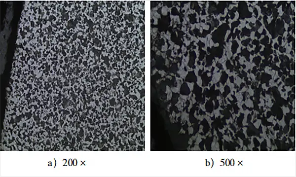
Based on the observation of the metallographic structure at equilibrium in Fig. 3, the microstructure morphology of the carburizing layer in low-carbon steel after slow cooling is significantly different from that of normal low-carbon steel. The hypereutectoid layer, eutectoid layer, and transition layer in the carburizing layer cannot be clearly and effectively distinguished.
The microstructure of low-carbon steel after carburizing and slow cooling should comprise a surface layer of pearlite and net cementite, an eutectoid structure inside, a transition zone of subeutectoid structure, and the original structure.
As for the equilibrium structure in Fig. 3, its morphology and structure are more similar to the equilibrium structure obtained after annealing ordinary medium-carbon steel, which has a uniformly distributed pearlite and ferrite structure. No obvious cementite is found, indicating that the carbon potential of the carburizing atmosphere in the furnace is insufficient to ensure sufficient carbon concentration on the workpiece surface.
Therefore, to obtain adequate carbon concentration on the workpiece surface and form an effective carbon concentration gradient, it is necessary to increase the carbon potential when the carburizing temperature is normal.
4. Improvement of process methods and conditions
The diffusion of carbon atoms from the surface to the center is necessary for carburizing and achieving a certain depth of the carburized layer.
The driving force behind diffusion is the carbon concentration gradient between the surface and the core.
To improve the carburizing effect, it is crucial to absorb activated carbon atoms on time to ensure the uniform circulation of the furnace atmosphere. The rate of carbon atoms provided (decomposition rate) should match the absorption rate to prevent insufficient supply and carbon deposition.
Through analysis of the original process links and test blocks, it was found that the low hardness of the actual workpiece was primarily due to the low carbon concentration on the surface of the carburizing layer caused by an insufficient atmosphere in the furnace. This resulted in ineffective carburizing treatment, preventing the formation of an ideal carburizing layer structure and achieving sufficient hardness.
To address this, targeted rectification measures were taken to overhaul the equipment, replace the carbon potential monitoring equipment, verify the tightness of the furnace body, and conduct carbon determination treatment on the furnace atmosphere again to ensure the uniformity and accuracy of the furnace atmosphere.
After re-evaluating the furnace conditions and resetting the carburizing and quenching process parameters, production can proceed.
Refer to Table 5 for the adjusted heat treatment process.
Table 5 adjusted heat treatment process
| NO. | Process parameters | Workpiece surface hardness (HRC) |
| 1 | Strong penetration: 930 ℃ x450min, carbon potential 1.3%; Diffusion: 930 ℃ x 30min, carbon potential 1.0%; Quenching insulation: 850 ℃ × 30min, carbon potential 1.0%; Tempering: 150 ℃ x240min | 62.6, 623, 62.1, 62.4, 62.9, 62.8 |
| 2 | Strong permeability: 920 ℃ × 450 min, carbon potential 1.3%; Diffusion: 920 ℃ x30min, carbon potential 1.0%; Quenching and heat preservation: 840 ℃ x30min, carbon potential 1.0%; Tempering: 180 ℃ x240min | 59.4, 613, 60.1, 59.4, 60.9, 60.1 |
The metallographic structure of the infiltrated layer of the test block treated by the adjusted heat treatment process is shown in Fig. 4.
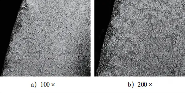
Figure 4 illustrates that the metallographic structure primarily consists of fine tempered martensite, fine-grained carbide, and a small amount of residual austenite, which aligns with the normal carburizing and quenching structure. This ensures effective surface hardness and overall surface hardness of the workpiece that meets the range required by the technical conditions.
To gain a better understanding of the microstructure changes pre and post the specific heat treatment process adjustments, the test block undergoes annealing with the same process.
The annealing process entails heating the block to 860 ℃ for 30 minutes, cooling it down to 500 ℃ in the furnace, and finally air cooling it.
Metallographic samples were prepared to observe the equilibrium structure of 20CrMo steel carburized parts.
Figure 5 demonstrates the annealed structure following the adjustment process heat treatment.
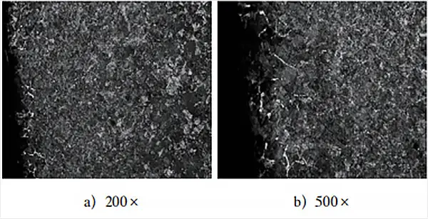
Fig. 5 clearly shows the presence of pearlite and reticulated cementite, and a comparison of the surface layer structure in Fig. 3 highlights the difference between them.
The structure depicted in Fig. 3 resembles the equilibrium structure of ordinary medium carbon steel after annealing, with a carbon content (mass fraction) of around 0.5%.
In contrast, the equilibrium structure in Fig. 5 displays the pearlite + network cementite structure that results from normal carburizing annealing.
This change in structure suggests that there was a significant issue with the furnace atmosphere under the original process conditions. As a result, the carburizing conditions of the workpieces failed to meet the set requirements, ultimately causing the workpieces to fall short of the specified technical requirements after the process treatment.
5. Conclusion
- The slow-cooling solid phase transformation structure of low-alloy carbon structural steel after carburizing and quenching can be used to determine the carbon content in the final carburized layer. This, in turn, helps determine whether the furnace atmosphere meets the required standards.
- Although increasing the carbon potential can enhance the carburizing effect to some extent, the limited saturated solubility of carbon in austenite necessitates a flexible carbon potential setting based on the actual conditions to avoid the possibility of carbon deposition.
- The precision of carburizing treatment equipment will directly impact the final heat treatment results.