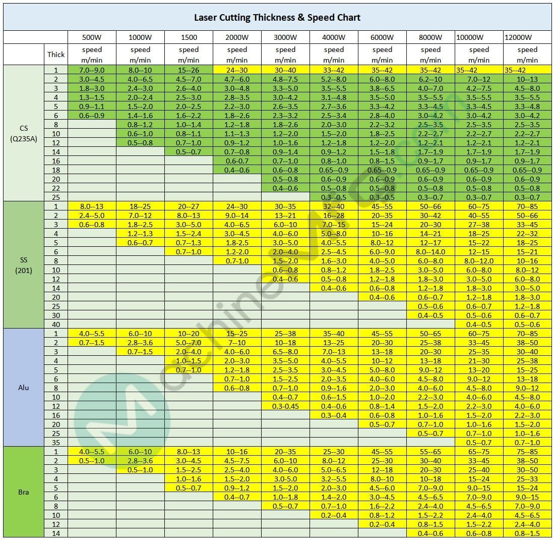
I. Laser Cutting Thickness & Speed Chart
1. 500W – 12kW Laser Cutting Thickness & Speed Chart
Unit: m/min
| Metals | 500W | 1000W | 1500 | 2000W | 3000W | 4000W | 6000W | 8000W | 10kW | 12kW | |
|---|---|---|---|---|---|---|---|---|---|---|---|
| Thickness | speed | speed | speed | speed | speed | speed | speed | speed | speed | speed | |
| Mild Steel (Q235A) | 1 | 7.0–9.0 | 8.0–10 | 15–26 | 24–30 | 30–40 | 33–42 | 35–42 | 35–42 | 35–42 | 35–42 |
| 2 | 3.0–4.5 | 4.0–6.5 | 4.5–7.0 | 4.7–6.0 | 4.8–7.5 | 5.2–8.0 | 6.0–8.0 | 6.2–10 | 7.0–12 | 10–13 | |
| 3 | 1.8–3.0 | 2.4–3.0 | 2.6–4.0 | 3.0–4.8 | 3.3–5.0 | 3.5–5.5 | 3.8–6.5 | 4.0–7.0 | 4.2–7.5 | 4.5–8.0 | |
| 4 | 1.3–1.5 | 2.0–2.4 | 2.5–3.0 | 2.8–3.5 | 3.0–4.2 | 3.1–4.8 | 3.5–5.0 | 3.5–5.5 | 3.5–5.5 | 3.5–5.5 | |
| 5 | 0.9–1.1 | 1.5–2.0 | 2.0–2.5 | 2.2–3.0 | 2.6–3.5 | 2.7–3.6 | 3.3–4.2 | 3.3–4.5 | 3.3–4.5 | 3.3–4.8 | |
| 6 | 0.6–0.9 | 1.4–1.6 | 1.6–2.2 | 1.8–2.6 | 2.3–3.2 | 2.5–3.4 | 2.8–4.0 | 3.0–4.2 | 3.0–4.2 | 3.0–4.2 | |
| 8 | 0.8–1.2 | 1.0–1.4 | 1.2–1.8 | 1.8–2.6 | 2.0–3.0 | 2.2–3.2 | 2.5–3.5 | 2.5–3.5 | 2.5–3.5 | ||
| 10 | 0.6–1.0 | 0.8–1.1 | 1.1–1.3 | 1.2–2.0 | 1.5–2.0 | 1.8–2.5 | 2.2–2.7 | 2.2–2.7 | 2.2–2.7 | ||
| 12 | 0.5–0.8 | 0.7–1.0 | 0.9–1.2 | 1.0–1.6 | 1.2–1.8 | 1.2–2.0 | 1.2–2.1 | 1.2–2.1 | 1.2–2.1 | ||
| 14 | 0.5–0.7 | 0.7–0.8 | 0.9–1.4 | 0.9–1.2 | 1.5–1.8 | 1.7–1.9 | 1.7–1.9 | 1.7–1.9 | |||
| 16 | 0.6-0.7 | 0.7–1.0 | 0.8–1.0 | 0.8–1.5 | 0.9–1.7 | 0.9–1.7 | 0.9–1.7 | ||||
| 18 | 0.4–0.6 | 0.6–0.8 | 0.65–0.9 | 0.65–0.9 | 0.65–0.9 | 0.65–0.9 | 0.65–0.9 | ||||
| 20 | 0.5–0.8 | 0.6–0.9 | 0.6–0.9 | 0.6–0.9 | 0.6–0.9 | 0.6–0.9 | |||||
| 22 | 0.4–0.6 | 0.5–0.8 | 0.5–0.8 | 0.5–0.8 | 0.5–0.8 | 0.5–0.8 | |||||
| 25 | 0.3–0.5 | 0.3–0.5 | 0.3–0.7 | 0.3–0.7 | 0.3–0.7 | ||||||
| Stainless Steel (201) | 1 | 8.0–13 | 18–25 | 20–27 | 24–30 | 30–35 | 32–40 | 45–55 | 50–66 | 60–75 | 70–85 |
| 2 | 2.4–5.0 | 7.0–12 | 8.0–13 | 9.0–14 | 13–21 | 16–28 | 20–35 | 30–42 | 40–55 | 50–66 | |
| 3 | 0.6–0.8 | 1.8–2.5 | 3.0–5.0 | 4.0–6.5 | 6.0–10 | 7.0–15 | 15–24 | 20–30 | 27–38 | 33–45 | |
| 4 | 1.2–1.3 | 1.5–2.4 | 3.0–4.5 | 4.0–6.0 | 5.0–8.0 | 10–16 | 14–21 | 18–25 | 22–32 | ||
| 5 | 0.6–0.7 | 0.7–1.3 | 1.8-2.5 | 3.0–5.0 | 4.0–5.5 | 8.0–12 | 12–17 | 15–22 | 18–25 | ||
| 6 | 0.7–1.0 | 1.2-2.0 | 2.0–4.0 | 2.5–4.5 | 6.0–9.0 | 8.0–14.0 | 12–15 | 15–21 | |||
| 8 | 0.7-1.0 | 1.5–2.0 | 1.6–3.0 | 4.0–5.0 | 6.0–8.0 | 8.0–12.0 | 10–16 | ||||
| 10 | 0.6–0.8 | 0.8–1.2 | 1.8–2.5 | 3.0–5.0 | 6.0–8.0 | 8.0–12 | |||||
| 12 | 0.4–0.6 | 0.5–0.8 | 1.2–1.8 | 1.8–3.0 | 3.0–5.0 | 6.0–8.0 | |||||
| 14 | 0.4–0.6 | 0.6–0.8 | 1.2–1.8 | 1.8–3.0 | 3.0–5.0 | ||||||
| 20 | 0.4–0.6 | 0.6–0.7 | 1.2–1.8 | 1.8–3.0 | |||||||
| 25 | 0.5–0.6 | 0.6–0.7 | 1.2–1.8 | ||||||||
| 30 | 0.4–0.5 | 0.5–0.6 | 0.6–0.7 | ||||||||
| 40 | 0.4–0.5 | 0.5–0.6 | |||||||||
| Aluminum | 1 | 4.0–5.5 | 6.0–10 | 10–20 | 15–25 | 25–38 | 35–40 | 45–55 | 50–65 | 60–75 | 70–85 |
| 2 | 0.7–1.5 | 2.8–3.6 | 5.0–7.0 | 7–10 | 10–18 | 13–25 | 20–30 | 25–38 | 33–45 | 38–50 | |
| 3 | 0.7–1.5 | 2.0–4.0 | 4.0–6.0 | 6.5–8.0 | 7.0–13 | 13–18 | 20–30 | 25–35 | 30–40 | ||
| 4 | 1.0–1.5 | 2.0–3.0 | 3.5–5.0 | 4.0–5.5 | 10–12 | 13–18 | 21–30 | 25–38 | |||
| 5 | 0.7–1.0 | 1.2–1.8 | 2.5–3.5 | 3.0–4.5 | 5.0–8.0 | 9.0–12 | 13–20 | 15–25 | |||
| 6 | 0.7–1.0 | 1.5–2.5 | 2.0–3.5 | 4.0–6.0 | 4.5–8.0 | 9.0–12 | 13–18 | ||||
| 8 | 0.6–0.8 | 0.7–1.0 | 0.9–1.6 | 2.0–3.0 | 4.0–6.0 | 4.5–8.0 | 9.0–12 | ||||
| 10 | 0.4–0.7 | 0.6–1.5 | 1.0–2.0 | 2.2–3.0 | 4.0–6.0 | 4.5–8.0 | |||||
| 12 | 0.3-0.45 | 0.4–0.6 | 0.8–1.4 | 1.5–2.0 | 2.2–3.0 | 4.0–6.0 | |||||
| 16 | 0.3–0.4 | 0.6–0.8 | 1.0–1.6 | 1.5–2.0 | 2.2–3.0 | ||||||
| 20 | 0.5–0.7 | 0.7–1.0 | 1.0–1.6 | 1.5–2.0 | |||||||
| 25 | 0.5–0.7 | 0.7–1.0 | 1.0–1.6 | ||||||||
| 35 | 0.5–0.7 | 0.7–1.0 | |||||||||
| Brass | 1 | 4.0–5.5 | 6.0–10 | 8.0–13 | 10–16 | 20–35 | 25–30 | 45–55 | 55–65 | 65–75 | 75–85 |
| 2 | 0.5–1.0 | 2.8–3.6 | 3.0–4.5 | 4.5–7.5 | 6.0–10 | 8.0–12 | 25–30 | 30–40 | 33–45 | 38–50 | |
| 3 | 0.5–1.0 | 1.5–2.5 | 2.5–4.0 | 4.0–6.0 | 5.0–6.5 | 12–18 | 20–30 | 25–40 | 30–50 | ||
| 4 | 1.0–1.6 | 1.5–2.0 | 3.0-5.0 | 3.2–5.5 | 8.0–10 | 10–18 | 15–24 | 25–33 | |||
| 5 | 0.5–0.7 | 0.9–1.2 | 1.5–2.0 | 2.0–3.0 | 4.5–6.0 | 7.0–9.0 | 9.0–15 | 15–24 | |||
| 6 | 0.4–0.7 | 1.0–1.8 | 1.4–2.0 | 3.0–4.5 | 4.5–6.5 | 7.0–9.0 | 9.0–15 | ||||
| 8 | 0.5–0.7 | 0.7–1.0 | 1.6–2.2 | 2.4–4.0 | 4.5–6.5 | 7.0–9.0 | |||||
| 10 | 0.2–0.4 | 0.8–1.2 | 1.5–2.2 | 2.4–4.0 | 4.5–6.5 | ||||||
| 12 | 0.2–0.4 | 0.8–1.5 | 1.5–2.2 | 2.4–4.0 | |||||||
| 14 | 0.4–0.6 | 0.6–0.8 | 0.8–1.5 | ||||||||
Note:
The following data in the laser cutting thickness & speed chart is for reference only!
Several factors can affect the cutting speed in laser technology, such as fiber optics, material quality, gases, optical lenses, cutting patterns, and other site-specific conditions that require adjustments.
The diagram shows that the yellow section represents pure nitrogen cutting, while the blue section represents pure oxygen cutting.
It is important to note that laser cutting may not be efficient when working with limited materials, which can result in suboptimal outcomes and hinder continuous processing.
When cutting highly anti-corrosive materials such as copper and aluminum, it is crucial to pay special attention to adjusting the process.
It is not recommended to process continuously for extended periods of time to avoid potential damage.
2. 750W Laser Cutting Thickness & Speed Chart
| Power | 750w | |||
|---|---|---|---|---|
| Material | Thickness (mm) | Speed (m/min) | Pressure (MPA) | Gas |
| Stainless steel | 0.5 | >21 | 1 | N2 |
| 1 | 12~18 | >1.1 | ||
| 2 | 3.6~4.2 | >1.5 | ||
| 3 | 1.2~1.8 | >1.8 | ||
| 4 | 0.78~1.2 | >2.0 | ||
| Carbon steel | 1 | 12~18 | 1 | O2 |
| 2 | 4.2~5.4 | 0.6~0.8 | ||
| 3 | 3~3.9 | 0.25~0.4 | ||
| 4 | 1.8~2.4 | 0.15~0.2 | ||
| 5 | 1.2~1.8 | 0.15~0.2 | ||
| 6 | 0.9~1.2 | 0.10~0.15 | ||
| 8 | 0.72~1.84 | 0.10~0.15 | ||
3. 20kW Laser Cutting Thickness & Speed Chart
Unit: m/min
| Metal | Mild Steel | Stainless Steel | Aluminum | Brass | ||||
| Thickness (mm) | O2 | O2 | Mix | Air | N2 | Air | N2 | N2 |
| (Positive Focus) | (Negative Focus) | (Mixed Gas/N2 Generator) | ||||||
| 1 | 7.0-10.0 | / | 30.0-80.0 | 30.0-80.0 | 30.0-80.0 | 30.0-80.0 | 30.0-80.0 | 30.0-80.0 |
| 2 | 5.0-7.0 | / | 30.0-50.0 | 30.0-50.0 | 30.0-50.0 | 30.0-50.0 | 30.0-50.0 | 30.0-50.0 |
| 3 | 4.5-6.0 | / | 25.0-40.0 | 25.0-40.0 | 25.0-40.0 | 25.0-40.0 | 25.0-40.0 | 25.0-45.0 |
| 4 | 3.5-3.9 | / | 25.0-35.0 | 25.0-35.0 | 25.0-35.0 | 25.0-35.0 | 25.0-35.0 | 20.0-35.0 |
| 5 | 3.2-3.5 | / | 20.0-28.0 | 20.0-28.0 | 20.0-28.0 | 20.0-28.0 | 20.0-28.0 | 14.0-24.0 |
| 6 | 2.9-3.2 | / | 18.0-28.0 | 18.0-28.0 | 18.0-28.0 | 18.0-28.0 | 18.0-28.0 | 12.0-20.0 |
| 8 | 2.5-2.7 | 3.2-3.8 | 13.0-16.0 | 13.0-16.0 | 13.0-16.0 | 13.0-18.0 | 13.0-18.0 | 8.0-13.0 |
| 10 | 1.9-2.2 | 3.2-3.6 | 8.0-10.0 | 8.0-10.0 | 8.0-10.0 | 8.0-11.0 | 9.0-12.0 | 6.0-9.0 |
| 12 | 1.8-2.1 | 3.1-3.5 | 7.0-8.0 | 7.0-8.0 | 7.0-8.0 | 7.0-8.5 | 5.0-7.5 | 4.0-6.0 |
| 14 | 1.6-1.8 | 3.0-3.4 | 5.5-6.5 | 5.5-6.5 | 5.5-6.5 | 5.5-7.0 | 4.5-5.5 | 3.5-4.5 |
| 16 | 1.5-1.7 | 3.0-3.3 | 4.0-5.0 | 4.0-5.0 | 4.0-5.0 | 4.0-5.3 | 2.5-4.5 | 3.0-4.0 |
| 18 | 1.5-1.6 | 3.0-3.3 | 3.0-3.8 | / | 3.0-3.8 | 3.0-4.0 | 2.0-3.5 | 2.5-3.5 |
| 20 | 1.3-1.5 | 2.6-3.2 | 2.6-3.2 | / | 2.6-3.3 | 2.6-3.6 | 1.5-2.0 | 1.5-2.5 |
| 22 | / | / | / | / | 1.6-2.6 | 1.6-2.8 | 1.2-1.8 | / |
| 25 | 0.8-1.3 | 2.2-2.8 | / | / | 1.2-2.0 | 1.2-2.2 | 1.0-1.5 | 0.5-0.8 |
| 30 | 0.7-1.2 | 2.0-2.7 | / | / | 0.8-1.0 | 0.8-1.2 | 0.7-1.2 | 0.3-0.5 |
| 35 | / | / | / | / | 0.4-0.7 | 0.4-0.8 | 0.5-0.9 | / |
| 40 | 0.8-1.1 | 1.0-1.3 | / | / | 0.3-0.6 | 0.3-0.7 | 0.3-0.5 | / |
| 50 | 0.3-0.6 | / | / | / | 0.2-0.4 | 0.2-0.4 | 0.2-0.3 | / |
| 60 | 0.2-0.5 | / | / | / | 0.2-0.3 | / | 0.1-0.2 | / |
4. 30kW Laser Cutting Thickness & Speed Chart
| Thickness (mm) | Metal | Cutting Speed (m/min) | Auxiliary Gas |
| 1 | Mild Steel | 10.0-15.0/30.0-80.0 | O2/N2 |
| 2 | 6.0-8.0/30.0-50.0 | ||
| 3 | 5.0-6.0/30.0-40.0 | ||
| 4 | 3.5-3.9/25.0-35.0 | ||
| 5 | 3.2-3.5/22.0-30.0 | ||
| 6 | 2.9-3.2/18.0-22.0 | ||
| 8 | 2.5-3.7/14.0-18.0 | ||
| 10 | 2-3.6/12.0-14.0 | ||
| 12 | 1.8-3.3/10.0-12.0 | ||
| 16 | 1.4-3.2/6.0-8.0 | ||
| 20 | 1.3-2.8/4.0-5.5 | ||
| 25 | 1.1-2.2/2.5-3.5 | ||
| 30 | 1.0-1.7 | O2 | |
| 40 | 0.7-0.9 | ||
| 50 | 0.3-0.4 | ||
| 60 | 0.15-0.2 | ||
| 1 | Stainless Steel | 30.0-80.0 | N2 |
| 2 | 30.0-50.0 | ||
| 3 | 25.0-45.0 | ||
| 4 | 25.0-35.0 | ||
| 5 | 20.0-28.0 | ||
| 6 | 24.0-32.0 | ||
| 8 | 20.0-27.0 | ||
| 10 | 16.0-22.0 | ||
| 12 | 11.0-13.0 | ||
| 16 | 7.5-9.5 | ||
| 20 | 4.5-5.5 | ||
| 25 | 2.5-3.0 | ||
| 30 | 1.5-2.1 | ||
| 35 | 1.0-1.1 | ||
| 40 | 0.6-0.8 | ||
| 50 | 0.2-0.3 | ||
| 60 | 0.1-0.2 | ||
| 70 | 0.1-0.16 | ||
| 1 | Aluminum | 30.0-80.0 | N2 |
| 2 | 30.0-60.0 | ||
| 3 | 25.0-50.0 | ||
| 4 | 25.0-40.0 | ||
| 5 | 23.0-35.0 | ||
| 6 | 22.0-30.0 | ||
| 8 | 18.0-25.0 | ||
| 10 | 10.0-14.0 | ||
| 12 | 5.8-8.5 | ||
| 16 | 3.5-8.0 | ||
| 18 | 2.5-6.5 | ||
| 20 | 2.0-4.0 | ||
| 22 | 1.5-3.0 | ||
| 25 | 1.0-2.0 | ||
| 30 | 0.8-1.5 | ||
| 35 | 0.6-1.2 | ||
| 40 | 0.5-1.0 | ||
| 50 | 0.4-0.6 | ||
| 60 | 0.3-0.4 | ||
| 1 | Brass | 30.0-80.0 | N2 |
| 2 | 30.0-50.0 | ||
| 3 | 25.0-45.0 | ||
| 4 | 24.0-35.0 | ||
| 5 | 17.0-24.0 | ||
| 6 | 12.0-20.0 | ||
| 8 | 9.0-15.0 | ||
| 10 | 6.0-10.0 | ||
| 12 | 3.7-6.5 | ||
| 16 | 2.4-3.3 | ||
| 20 | 1.1-2.4 | ||
| 25 | 0.7-1.6 | ||
| 30 | 0.55-0.9 |
See also:
- 750-6000W Fiber Laser Cutting Speed (Raycus Laser Source)
- 1000-6000W Fiber Laser Cutting Speed (IPG Laser Source)
- CO2 Laser Cutting Thickness & Speed chart
- Bystronic Laser Cutting Chart
II. Parameters for Laser Cutting Stainless Steel
| Stainless steel material thickness | mm | 1 | 2 | 3 | 4 | 5 | 6 | 8 |
| Incident beam diameter | mm | 19 | 19 | 19 | 19 | 19 | 19 | 19 |
| Cutting auxiliary gas | N2 | N2 | N2 | N2 | N2 | N2 | N2 | |
| Auxiliary gas pressure | bar | 8 | 10 | 13 | 15 | 17 | 18 | 20 |
| Cutting nozzle diameter | mm | 1.5 | 2 | 2 | 2 | 2 | 2 | 2.5 |
| Position of the cutting nozzle relative to the material | mm | 1 | 1 | 0.8 | 0.8 | 0.8 | 8 | 0.8 |
| Cutting seam width | mm | 0.1 | 0.1 | 0.12 | 0.12 | 0.12 | 0.12 | 0.12 |
| Lens focal length | inch | 5 | 5 | 5 | 5 | 5 | 5 | 7.5 |
| Focal point position | -0.5 | -1 | -2 | 3 | -3.5 | -4.5 | -6 | |
| Piercing | ||||||||
| Laser Mode | SP | SP | SP | SP | SP | SP | SP | |
| Laser Frequency | Hz | 200 | 200 | 200 | 250 | 250 | 250 | 250 |
| Laser Power | W | 600 | 800 | 800 | 1100 | 1100 | 1350 | 1350 |
| Duty Cycle | % | 20 | 25 | 25 | 25 | 25 | 25 | 25 |
| Delay Time | Sec | 2 | 2 | 0.5 | 1 | 1 | 1 | 2 |
| Focal Position | mm | -0.5 | -1 | -2 | 0 | 0 | 0 | 0 |
| Auxiliary O2 Pressure | bar | 1 | 1 | 1 | 2 | 1 | 1 | 1 |
| Small Hole | ||||||||
| Laser Mode | SP | SP | SP | CW | CW | CW | CW | |
| Laser Frequency | Hz | 200 | 750 | 750 | ||||
| Laser Power | W | 800 | 1200 | 1200 | 1500 | 1500 | 1800 | 2200 |
| Duty Cycle | % | 25 | 50 | 55 | ||||
| Feed Rate | mm/min | 500 | 1300 | 1000 | 900 | 700 | 800 | 500 |
| Large Hole | ||||||||
| Laser Mode | CW | CW | CW | CW | CW | CW | CW | |
| Laser Power | W | 1200 | 1500 | 1500 | 2200 | 2200 | 2200 | 2200 |
| Feed Rate | mm/min | 3000 | 2500 | 1800 | 1600 | 1300 | 1000 | 500 |
| Cutting | ||||||||
| Laser Mode | CW | CW | CW | CW | CW | CW | CW | |
| Laser Power | W | 800 | 1100 | 1800 | 1800 | 1800 | 1500 | 1500 |
| Feed Rate | mm/min | 1500 | 2000 | 2500 | 1350 | 1100 | 500-800 | 275 |
| Laser Mode | CW | CW | CW | CW | CW | CW | CW | |
| Laser Power | W | 1500 | 1800 | 2200 | 2200 | 2200 | 2200 | 1800 |
| Feed Rate | mm/min | 4000 | 3500 | 2700 | 1600 | 1300 | 1000 | 350 |
| Laser Mode | CW | CW | CW | |||||
| Laser Power | W | 1800 | 2200 | 2200 | ||||
| Feed Rate | mm/min | 5600 | 3750 | 500 | ||||
| Laser Mode | CW | |||||||
| Laser Power | W | 2200 | ||||||
| Feed Rate | mm/min | 6000 | ||||||
- CW-Continuous Wave
- SP-Super Pulse
- GP-Gated Pulse
Precautions:
For oxygen-assisted cutting, additional thickness and other material parameters are related to the PRC parameters.
At the highest cutting speed, the edge trimming quality and cutting gas pressure depend on the alloy composition of the material and the purity of the cutting gas.
After the oxygen cutting is completed, the oxygen must be purified; otherwise, the mixture of oxygen and nitrogen will cause the cutting edge to turn blue or brown.
When cutting material with thickness ≥4mm, the parameters for cutting small holes should be used when cutting φ1.5mm holes, with oxygen pressure at 4Bar (60Psi), or the starting cutting speed is 20~30% of the normal cutting speed.
Cutting small holes refers to holes with a diameter ≤5mm and a thickness ≤3mm, or a thickness >3mm and a hole diameter not larger than the thickness of the plate.
Cutting large holes refers to holes with a diameter >5mm and a thickness ≤3mm, or a thickness >3mm and a hole diameter larger than the thickness of the plate.
Methods to Increase Laser Cutting Speed
The methods to increase laser cutting speed primarily include the following aspects:
Adjusting laser power: The magnitude of laser power directly impacts the cutting speed, seam width, cutting thickness, and cutting quality. Appropriate laser power can enhance cutting efficiency, but it is important to note that the required power depends on the characteristics of the material and the cutting mechanism. For example, when cutting carbon steel, the cutting speed can be increased by changing the type of cutting gas.
Optimizing cutting parameters: Rational settings of cutting speed, power, and gas cutting have a significant impact on cutting quality and efficiency. By simulating cutting plans, the optimal cutting path can be determined to avoid excessive repetition of cuts and travel paths, thereby increasing cutting speed.
Improving the cutting head structure: Choosing the right cutting gas and improving the cutting head structure is also one of the effective methods to increase cutting speed.
Adjusting cutting parameters according to material characteristics: Different metal materials (such as aluminum sheet, stainless steel, carbon steel, copper sheet, and alloy materials, etc.) and material thickness will affect the speed of laser cutting. Therefore, it is necessary to adjust the cutting parameters according to the specific characteristics of the material.
Improving equipment performance: Enhancing the power of the laser generator to reach the ideal value can directly and effectively improve the cutting speed and cutting effect.
Adjusting beam mode and focus distance: By adjusting the mode of the beam and ensuring a change in laser cutting speed within a certain range, pay attention to adjusting laser power, cutting speed, and focus distance to achieve the best cutting effect.
Using an autofocus laser cutting head: The use of an autofocus laser cutting head can improve the machine’s focusing speed, avoiding time wastage caused by manual focusing, thereby indirectly increasing the cutting speed.
Which Cutting Parameters (Such as Cutting Speed, Power) Are Most Critical for Improving Cutting Efficiency Under Different Laser Powers?
Under different laser powers, the key parameters for improving cutting efficiency include cutting speed, laser power, focus size, and focus depth. Firstly, laser power is one of the important factors affecting cutting speed and efficiency. With the increase of laser power, faster cutting speed can be achieved, especially when processing medium and low thickness plates, the increase of laser power can significantly improve cutting efficiency.
In addition, the correct focus position is crucial for obtaining stable and efficient cutting quality. Besides the above parameters, the choice and flow of auxiliary gases also have a significant impact on cutting efficiency.
Oxygen can participate in metal combustion and is suitable for cutting most metals, while inert gases and air are suitable for cutting some metals. This suggests that when choosing the parameters of a laser cutting machine, not only should the laser power and focus settings be considered, but also the choice and flow of auxiliary gases should be adjusted according to the characteristics and requirements of the material being cut.
The key parameters for improving laser cutting efficiency include laser power, cutting speed, focus size, focus depth, and the choice and flow of auxiliary gases. These parameters need to be optimized and adjusted according to the specific cutting task and material characteristics.
How to Optimize Beam Pattern and Focus Distance for Best Cutting Results?
In the process of laser cutting, optimizing the beam pattern and focus distance to achieve the best cutting effect is crucial. Initially, the appropriate focus position must be chosen based on different materials and cutting requirements. The position of the focus can influence the fineness of the cut material’s cross-section, the condition of slag at the bottom, and whether the material can be severed.
For instance, in fiber laser cutting machines, the smallest slit and highest efficiency can be achieved when the focus is in the optimal position. Additionally, when the focus of the laser beam is minimized, point shooting is used to establish initial effects, and the focus position is determined based on the size of the light spot effect. This position is the optimal processing focus.
In addition to adjusting the focus position, the beam pattern can be optimized using diffractive multifocal optical elements. These unique diffractive optical components can separate the beam on the focus axis, demonstrating improved bevel cutting effects. Furthermore, a beam shaper is also an important tool that can improve cutting effects by causing incident light to diffract through an optimization algorithm.
In practical operations, it’s crucial to correctly set the focus distance for the cutting effect. Solutions include adjusting to the optimal cutting focus distance, using weights to flatten the material, and using a focus ruler to check whether the height of each area of the worktable is consistent. Moreover, optimizing the distance between processing points is an aspect of improving cutting quality. For example, when the processing point distance is 1 μm, a better quality of the processing cross-section roughness can be obtained.
By precisely adjusting the focus position, optimizing the beam pattern using diffractive optical components and beam shapers, and paying attention to the settings of focus distance and processing point distance, the beam pattern and focus distance during laser cutting can be effectively optimized to achieve the best cutting effect.

What is your assumed spot size?
You can check out the spot size formula here: http://www.machinemfg.com/laser-cutting-quality-control/#The_effect_of_the_beam_on_cutting_quality
am wondering about the kerf .. is the cut acceptable at the slower speeds/upper limits of the thickness for performance of each wattage?
You can read this post about laser cutting kerf: http://www.machinemfg.com/things-you-should-know-about-laser-cut-kerf/