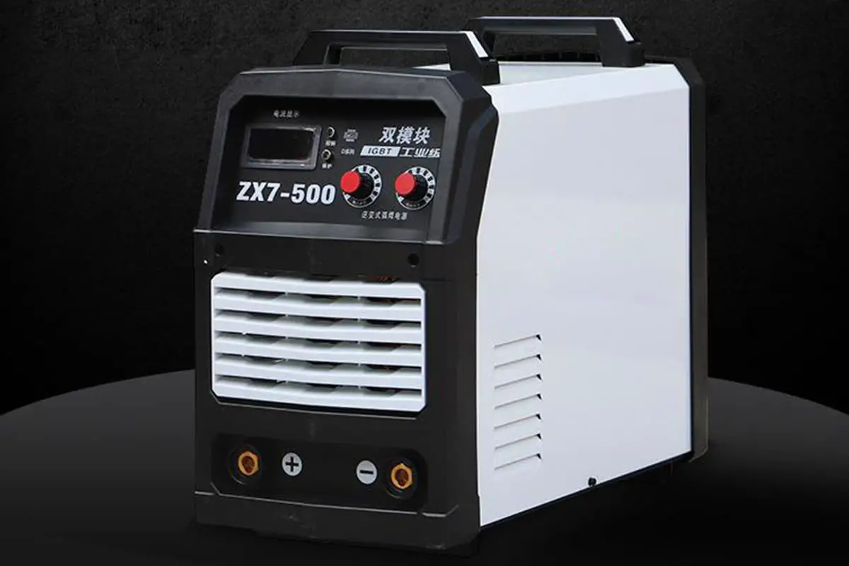
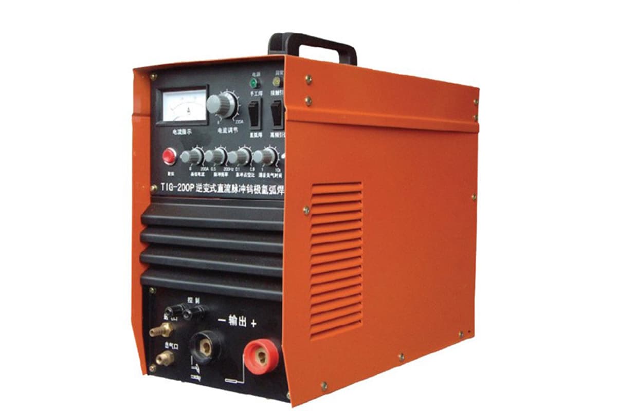
The inverter arc welding power source, also known as an arc welding inverter, is a new type of welding power source. This type of power source generally takes the three-phase mains frequency (50Hz) AC network voltage, rectifies and filters it through an input rectifier, converting it into DC.
It then uses high-power switching electronic components (such as thyristors SCR, GTO transistors, MOSFETs, or IGBTs) to alternate the switch state, inverting it into mid-frequency AC voltage ranging from several kHz to tens of kHz, which is then reduced by a transformer to a voltage suitable for welding.
After rectification and filtering through an inductance, it outputs stable DC welding current.
1. Inverter and Inverter Arc Welding Power Source
A device that converts DC into AC is called an inverter.
The conversion sequence can be simply represented as: mains frequency AC (after rectification and filtering) → DC (after inversion) → mid-frequency AC (after voltage reduction, rectification, and filtering) → DC. If expressed in symbols, it is:
AC → DC → AC → DC
This system is generally used because if the inverted and reduced AC current is directly used for welding, the high frequency will result in a large reactive power in the welding circuit, which will greatly reduce the active power. Therefore, rectification is required again.
2. Characteristics of Inverter Power Source
The basic feature of inverter arc welding is that it operates at a high frequency, which brings many advantages.
This is because the potential E of the transformer, whether it is the primary or secondary winding, has the following relationship with the frequency f of the current, magnetic flux density B, iron core section area S, and number of turns W of the winding:
E = 4.44fBSW
And the winding terminal voltage U is approximately equal to E, that is:
U ≈ E = 4.44fBSW
When U and B are determined, if the frequency f is increased, S will decrease and W will decrease. Therefore, the weight and volume of the transformer can be greatly reduced. This makes the weight and volume of the whole machine significantly smaller.
Moreover, due to the increase in frequency and other factors, it brings many advantages compared with traditional arc welding power sources. The main characteristics are as follows:
(1) Small size, light weight, material saving, and easy carrying and movement.
(2) High efficiency and energy-saving, with an efficiency of up to 80% to 90%, saving more than one-third of electricity compared to traditional welding machines.
(3) Good dynamic characteristics, easy arc starting, stable arc, beautiful weld formation, and less spatter.
(4) Suitable for combination with robots to form an automatic welding production system.
(5) Can be used for multiple purposes, completing various welding and cutting processes.
Due to the series of advantages of inverter power sources mentioned above, it has developed rapidly since its appearance in the late 1970s. In industrialized countries such as the United States and Japan, its application scope is quite extensive.
The switching elements used in inverter power sources now include SCR (thyristor), GTR (transistor), MOSFET (field-effect transistor), and IGBT (a kind of electronic element that combines the advantages of GTR and MOSFET).
IGBT has the potential to replace other switching elements. IGBT inverter welding machine is a significant progress in welding technology and a new trend of development.
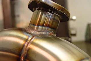
The welding machine head converts the energy output from the welding power source into welding heat and continuously feeds it into the welding material while the machine head moves forward to achieve welding.
The electric welding tongs used in manual arc welding need to be manually pushed down and moved forward to form a weld bead as the welding rod melts. Automatic welding machines have automatic wire feeding mechanisms and machine head moving mechanisms to move the machine head forward.
There are two commonly used types: carriage and suspension types.
The welding heads for spot welding and projection welding are electrodes and their pressing mechanisms, which are used to apply pressure and electricity to the workpiece.
For seam welding, there is a transmission mechanism to drive the workpiece to move. For butt welding, static and dynamic fixtures and fixture clamping mechanisms, as well as moving fixtures and upsetting mechanisms, are needed.
3. Development Direction of Inverter Power Sources
The general trend of inverter power source development is towards large capacity, lightweight, high efficiency, modularization, and intelligence, with improving reliability, performance, and expanding applications as its core. It is increasingly widely used in various arc welding methods, resistance welding, cutting processes, etc.
Efficiency and high power density (miniaturization) are the main goals pursued by international arc welding inverters. High-frequency and reducing the power consumption of the main components are the main technical approaches to achieve this goal.
Currently, in countries such as Japan, Europe, and other regions, the arc welding inverter technology at around 20kHz has matured, the quality of the products is high, and the products have been serialized.
Analyzing the Harmonic Suppression of the Inverter Welding Machine Power Supply
1. Harmonic Analysis of Arc Welding Inverter Power Supply
1.1 Reasons for Harmonic Generation
Since the first 300A thyristor arc welding inverter power supply, arc welding inverter power supply has undergone significant development, experiencing thyristor inversion, high-power transistor inversion, field effect inversion, and IGBT inversion. Its capacity and performance have been greatly improved.
At present, arc welding inverter power supply has become the mainstream product of welding equipment in industrialized countries .
As a typical power electronic device, although arc welding inverter power supply has the advantages of small size, light weight, and good control performance, its circuit contains rectification and inversion links, which cause current waveform distortion and generate a large number of high-order harmonics.
There is a serious phase shift between high-order voltage and current harmonics, which results in a very low power factor of the welder. The main reasons for harmonic generation are as follows:
(1) Internal Interference Sources of Inverter Power Supply
The inverter power supply is a system that combines strong and weak currents. During the welding process, the welding current can reach several hundred or even thousands of amperes. Since the current generates a large electromagnetic field, especially in welding power supply systems with high inversion frequency, rectifier tubes, high-frequency transformers, control system oscillations, high-frequency arc ignition, and power tube switches will produce strong harmonic interference.
Additionally, when the tungsten argon arc welding machine uses high-frequency arc ignition, it utilizes a frequency of up to several hundred thousand Hertz and a high voltage of several kilovolts to break through the air gap to form an arc, so high-frequency arc ignition is also a strong source of harmonic interference.
For intelligent arc welding inverter power supplies controlled by computers, since the operating speed of the computer control system used increases, the control board itself has become a source of harmonic interference, and higher requirements have been placed on the wiring of the control board.
(2) External Interference Sources of Inverter Power Supply
Pollution on the power grid is a severe interference for the power supply system because loads applied to the power grid constantly vary, causing more or less harmonic interference to the power grid.
Large power equipment can cause distortion of the power grid voltage waveform, accidental factors can cause momentary power outages, and high-frequency equipment can generate high-frequency pulses and peak pulse components in the power grid voltage waveform.
Furthermore, in the welding workshop, due to the possibility of interconnection between grounding wires of different welding power supplies during use, if corresponding measures are not taken, harmonic signals with high-frequency components can easily enter the control system, causing the power supply to malfunction or even damage it.
1.2 Characteristics and Hazards of Harmonics
Arc welding inverter power supply is known for its high-efficiency energy conversion. With the development of power control devices towards practical and large-capacity directions, arc welding inverter power supplies will also enter an era of high frequency and large capacity.
For the power grid, the arc welding inverter power supply is essentially a large rectifier power supply. Due to the sharp rise and fall of pulses generated by power electronic components during commutation, serious harmonic interference is caused.
The input current of the inverter power supply is a type of spike waveform, which contains a large number of high-order harmonics in the power grid.
There is a serious phase shift between high-order voltage and current harmonics, resulting in a very low power factor of the welder. Low-frequency distortion is currently a common problem with power electronic equipment, drawing significant attention in communication and home appliance industries.
Additionally, currently, inverter welders mostly use hard switching methods, inevitably causing harmonic interference in space during the power component’s switch process.
These interferences form conducted interference through near-field and far-field coupling, seriously polluting the surrounding electromagnetic environment and power supply environment, not only reducing the reliability of the inverter circuit itself but also severely affecting the operating quality of the power grid and adjacent equipment.
2. Harmonic Suppression Measures Commonly Used in Arc Welding Inverter Power Supplies
2.1 Passive Filters (PF)
The traditional method for harmonic suppression and reactive power compensation is electric passive filter technology, also known as indirect filtering method. This method involves the use of electric capacitors or other passive devices to construct a passive filter with nonlinear loads that need compensation connected in parallel, providing a low-impedance path for harmonics while supplying the required reactive power for the load.
Specifically, the distorted 50Hz sine wave is decomposed into the fundamental wave and various related main harmonic components, then using the series resonant principle, each filtering branch composed of L, C (or R) is tuned (or biased tuning) to various main harmonic frequencies to form a low impedance path and filter them out [2-3]. It passively defends against and reduces the harm of harmonics to electrical equipment that have already been generated.
Passive filtering schemes are low-cost and mature technologies but also have the following drawbacks:
(1) the filtering effect is affected by the system impedance;
(2) due to the fixed resonant frequency, it has poor effectiveness for cases of frequency deviation;
(3) it may cause overload due to series or parallel resonance with the system impedance. In small and medium power situations, passive filters are gradually being replaced by active filters.
2.2 Active Filters (AF)
As early as the early 1970s, scholars proposed the basic principle of active power filters. However, due to the lack of high-power switching devices and corresponding control technologies at that time, only compensation currents generated by linear amplifiers and other methods could be used, which had fatal weaknesses in low efficiency, high cost, and difficulty in large-capacity.
With the improvement of power semiconductor switching device performance and the development of corresponding PWM technology, it became possible to develop a large-capacity, low-loss harmonic current generator, making active filtering technology practical.
When a harmonic source appears in the system, a compensating current equal in magnitude and opposite in phase to the harmonic current is generated by some method, and connected in parallel with the circuit becoming the harmonic source to cancel out the harmonic component of the harmonic source, allowing the DC-side current to contain only the fundamental component, without harmonic components.
When the harmonic current generated by the harmonic source cannot predict what higher-order harmonic current it is or changes at any time, the harmonic current signal ih is detected from the load current il, and then modulated by the modulator and converted into a switching mode control current in accordance with a specified method to operate the current inverter to generate compensating current ifm and inject it into the circuit to cancel out the harmonic current ih.
The inverter’s main circuit generally uses a DC/AC full-bridge inverter circuit, where the switching devices can be GTO, GTR, SIT, or IGBT and other high-power controllable power semiconductor devices to control the output current waveform by the switching device’s on-off state, generating the required compensating current.
Electric active filters are the most promising power devices for suppressing power grid harmonics and compensating reactive power, improving power supply quality.
Compared with electric passive filters, they have the following advantages:
(1) dynamic compensation is achieved, and changes in frequency and magnitude of harmonic and reactive power can be compensated, with a very fast response to changes in the compensation object;
(2) simultaneous compensation for both harmonics and reactive power is possible, with the size of the compensated reactive power continuously adjustable;
(3) no energy storage device is required when compensating reactive power, and the required energy storage device capacity when compensating harmonics is not large;
(4) even if the compensated current is too large, the electric active filter will not overload and can function normally for compensation;
(5) it is not easily affected by the power grid impedance and does not easily resonate with the power grid impedance;
(6) it can track changes in power grid frequency, and the compensation performance is not affected by changes in frequency;
(7) it can compensate for a single harmonic and reactive power or concentrate on compensating multiple harmonics and reactive power.
3. Soft Switching Technology
As power electronics technology develops towards high-frequency and high-power density, the switch loss and harmonic interference of hard switching become increasingly prominent.
Soft switching technology is beneficial for any switch power converter in terms of improving conversion efficiency, device utilization, enhancing electromagnetic compatibility, and device reliability.
It is particularly necessary in some special cases (such as power density requirements or limited heat dissipation conditions). Among the two types of soft switching technology, passive soft switching without additional switching devices, detection methods, and control strategies has many advantages such as low additional cost, high reliability, high conversion efficiency, and high performance-price ratio.
In the field of single-ended converter manufacturing, it has basically established a mainstream position.
As for topology, the method of series inductance and parallel capacitance is the only passive soft switching means, and the so-called passive soft switching technology derived from it is actually lossless absorption technology.
Regarding bridge inverter circuits, from the early energy-absorbing type to later proposed partial feedforward type, and lossless solutions, they all have problems such as strong load dependency, narrow working frequency range, high additional stress, overly complex network, etc., making their practicality relatively poor.
At the same time, under the trend of modularization of switch power devices, the space available for placing absorbing elements is getting smaller and smaller, and lossless absorption technology suitable for inverter modules is rarely seen in literature.
Overall, passive absorption technology suitable for inverter module applications is still undergoing further research and development due to its special structure and difficulty.
4. Conclusion
Arc welding inverter power supplies generate a large amount of harmonics, which can cause serious harm.
In order to suppress harmonics and improve power factor, corresponding suppression measures must be taken. The traditional passive filter method has obvious limitations, which restricts its application, while the active filter method can compensate for the shortcomings of passive filters, effectively suppressing harmonics in arc welding inverter power supplies and has been widely used. Soft switching technology can also achieve good filtering effects to some extent.