Classification of turret punch dies
Let’s take Amada punch as an example:
AMADA CNC punch molds can be divided into two categories: original molds (metal return plate) (Fig. 1) and domestic molds (rubber return plate) (Fig. 2).
Based on the mold shape, they are classified as round mold, waist round mold, rectangular mold, square mold, special-shaped mold, forming mold (sample punch, bump, counterbore, turn over hole, shutter, and crimping die).
The die size determines the corresponding stations, which are divided as follows:
Station X
Usually round mold( φ1.6~ φ12.7) and front sample die.
Corresponding to 10 stations of the machine tool;
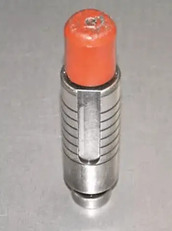
Fig. 1 original mold (metal return plate)

Fig. 2 domestic mold (rubber return plate)
Station B
This includes round dies (φ13φ27), square dies (SQ4SQ16), partial rectangular dies, partial waist round dies, and partial special-shaped dies (such as keyhole, cross, trapezoid, hexagonal, and single D dies). Additionally, there are forming dies (reverse sample punch, bump, counterbore, hole turning die, etc.) that correspond to the 16 stations on the machine tool.
Station C
Revised version:
The available die types include round dies (φ30~φ37), square dies (SQ20), partial rectangular dies, partial waist round dies, and partial special-shaped dies (double ear dies). These correspond to the 6 stations of the machine tool.
Station D
This product includes round dies (φ40-φ50), a square die (SQ35), partial rectangular dies, and partial waist round dies. These are designed to correspond to the 4 stations of a machine tool.
Station E, F
The main components of the machine are the cutter (RE60x4, RE60x5), square die (SQ50), and special-shaped die (nine-hole die). These correspond to the two stations of the machine tool.
Station G, H
Cutter (RE80x6), special-shaped die (shutter).
Corresponding to 2 stations of machine tool;
Station I
Indexing rotation station, is used to install the mold to be rotated.
It corresponds to 4 stations of the machine tool.
Selection of lower die
The general rule is to select the lower die clearance according to the material thickness of the workpiece to be processed, as shown in Table 1.
Table 1 Selection of lower die clearance
| Material thickness (mm) | 0.5-1.0 | 1.2 | 1.5 | 2.0-3.0 | 4.0 |
| Clearance (mm) | 0.1-0.15 | 0.15-0.2 | 0.3-0.40 | 0.4-0.6 | 0.6-0.8 |
It should be noted that typically, the lower die specified for the upper die has a gap of only 0.1mm to 0.4mm.
However, when processing plates thicker than 3mm, flexibility in selection is necessary. For instance, when working with a 4mm copper plate, the maximum clearance of the φ6.5 lower mold is only 0.4mm. In this case, a φ7.1 (0.15mm) lower die can be used instead.
Installation of lower die
Open the turret cover → rotate the machine tool to the station where the lower die is to be installed → remove the lower die base with the specified tool → put the lower die into the corresponding empty station → check the height (the lower die height can be 1mm ~ 2mm higher than the die base. If the height of the die itself is not enough, add shims to adjust it to reach the standard height) → tighten the screws → install the lower die base to the turret → fix the lower die base on the turret with the specified tool → the lower die installation is completed.
The installation sequence of the lower die is shown in Figure 3.
Fig. 3 installation sequence of lower die
Installation of upper die
To install the mold correctly, follow the mold angle as shown on the mold list. The steps for proper installation are as follows:
For the original mold sleeve or domestic mold sleeve, install them according to the selected upper mold. Generally, for the fixed station, the domestic mold sleeve can only be installed at 0 ° or 90 °, while the original mold sleeve can be installed at 0 °, 45 °, and 90 °.
Insert the upper mold into the selected mold sleeve, ensuring that the corresponding pin is placed in the corresponding groove. The original mold sleeve can automatically slide into the bottom of the mold sleeve. Sometimes, the domestic mold sleeve may need a gentle tap on the edge of the mold with a copper rod to slide it into the bottom of the mold sleeve.
Cover the return plate and check the height of the upper die. To ensure that the height of the upper die is flush with or slightly lower than the return plate within 0.5mm, select the matching return plate.
It is strictly prohibited for the height of the die to exceed the return plate.
If the height of the die itself does not meet the specified requirements, add or remove the gasket in the die sleeve until the die reaches the required height. After the die height reaches the standard, tighten the screws behind the die sleeve first, and then tighten the screws on the return plate.
Open the turret cover and rotate the turret to the corresponding upper die station after installing the lower die. It is essential to ensure that the installation angle of the upper and lower die is consistent.
Then, put the die vertically into the station so that it can slide freely until the corresponding pin is fully placed in the corresponding slot. The red indicator light turns on after the induction chuck of the turret is tightened, indicating the completion of the upper die installation.
Station selection optimization
Select the mold that matches the station and give priority to the vacant station. If there are not enough stations available, consider using the less commonly used mold station to ensure that the commonly used molds are always in the machine station. This will facilitate a smoother processing process with fewer mold changes.
Rotary station installation
The machine tool is equipped with four rotating stations.
The lower die of the rotating station defaults to 0°, which means that the upper die can only be installed at this angle (this is important).
The installation steps are as follows:
To begin, install the lower die into the indexing converter. Before clamping the lower die converter into the positioning groove, ensure that the lower turret of the indexing station is free of any dirt or debris.
Next, install the upper mold. Once the upper mold has been installed, double-check that the angles of both the upper and lower molds are consistent.
Finally, place the upper mold into the turret with the positioning groove located at the upper right.