1. Preamble
Tapers are widely utilized in mechanical matching and assembly. When a designer specifies the taper size of an inner hole and requires the machining of an outer cone to match it, the task can prove challenging for operators as the taper of the outer cone is difficult to control and measure.
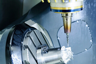
At Panzhihua Iron and Steel Co., Ltd., the main plant area is equipped with C6120 and CA6140 machining equipment. When turning a cone with a small sliding plate, the minimum deflection accuracy of the lathe is 1 degree, which makes it difficult to meet the high precision requirements for machining the outer cone.
To meet the matching requirements, other measuring instruments are used to control the taper of the cone through a relative measurement method.
2. Manual turning of short conical small sliding plate
The parts shown in Fig. 1 are mainly composed of cone and thread.
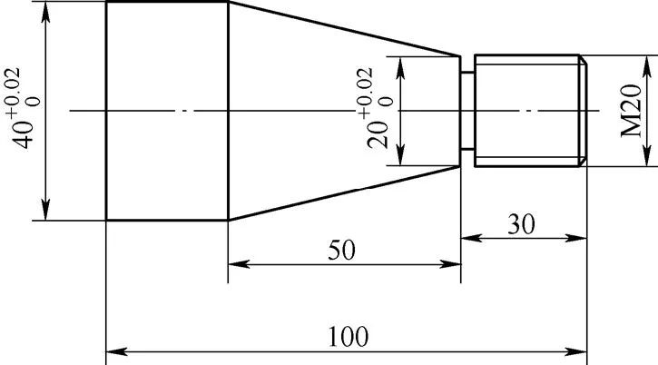
Fig. 1 parts
The dimensions of the cone are depicted in Figure 2, primarily consisting of:

Fig. 2 main dimensions of conical part
- Cone angle α, which is the angle between two radial lines.
- Cone half angle α/2, which is the rotation angle of the smaller sliding plate during turning.
- Maximum end diameter D, commonly referred to as the large end diameter.
- Minimum end diameter d, commonly referred to as the small end diameter.
- Cone length L, which is the distance between the large end diameter and the small end diameter along the axis.
When turning a taper, the rotation angle of the smaller sliding plate is α/2, as depicted in Figure 3.

Fig. 3 Schematic diagram of rotation angle of small sliding plate
The rotation angle of the smaller sliding plate, α/2, can be calculated using the trigonometric function relationship: tan(α/2) = (D – d)/(2L) = (40 – 20)/(2 x 50) = 0.2, resulting in α/2 = 11°20′.
The rotation angle of the smaller sliding plate is 11°20′, and its rotation angle is divided into 1° increments, without any sub-division into 20′. Measuring the angle with a universal angle ruler is a time-consuming and labor-intensive process, and it also results in an inaccurate cone angle. This leads to low accuracy of the workpiece, making it difficult to meet the matching requirements.
To address this issue, the shaded right triangle in Figure 2 (refer to Figure 4) was analyzed.

Fig. 4 Shaded right triangle
During the turning of the taper, the travel path of the turning tool is from point C to point B. The length of this travel path can be calculated using the Pythagorean theorem (refer to Figure 5).

Fig. 5 Length of turning tool travel path
During turning, the position of the tool tip relative to points B and C can be adjusted using the dial on the small sliding plate.
When the tool moves a distance of 50.99mm, the distance between the tool tip and the axis of the lathe should measure 10mm, indicating that the conical angle of the turning is correct. If not, the rotation angle of the small sliding plate is incorrect.
It is recommended to simulate the machining process before actual machining of a taper.
To determine if the rotation angle of the small sliding plate is correct, first adjust the small sliding plate so that the tool moves a distance of 50.99mm, then use a measuring tool to check if the distance between the tool tip and the axis of the lathe is 10mm.
This process can be repeated until the correct cone angle is achieved. The steps are illustrated in Figure 6.

Fig. 6 Schematic diagram of specific operation method
(1) Start by turning a section of the outer circle. The surface roughness should have a low value and there should be no taper along the length of the cylinder.
To ensure the absence of taper, measure the two ends of the cylinder with a micrometer and compare the dimensions. If they are equal, it means the cylinder has no taper.
(2) Calculate the dial indicator’s movement and determine the BC side length using the Pythagorean theorem, which is the exact distance the small sliding plate needs to travel when the car is tapered (BC = 50.99mm).
(3) Rotate the small sliding plate counterclockwise to 11° to 12°, secure it with a screw, and then attach the base of the dial indicator to the tool holder on the small sliding plate. Push the dial indicator’s contact onto the outer circle (refer to Fig. 6).
(4) Align the small sliding plate with the zero position and aim the dial indicator at the 10mm scale position. Move the small sliding plate forward, and the dial indicator’s contact will gradually extend.
If the small sliding plate moves 50.99mm and the dial indicator moves less than 10mm, it indicates a small taper. In this case, loosen the locking screw to increase the taper.
If the small sliding plate moves 50.99mm and the dial indicator moves more than 10mm, it indicates a large taper. Reduce the taper in this case.
If the small sliding plate moves 50.99mm and the dial indicator moves 10mm, it means the taper is correct, and turning can proceed.
Precautions during adjustment are as follows:
(1) It is important to note that the outer circle used to determine the taper should not have a taper itself, as this will result in inaccurate measurements.
If the turned outer circle does have a taper, align it by pressing the dial indicator against the tailstock sleeve.
(2) To ensure accurate readings, make sure the magnetic base of the dial gauge is securely attached and the connecting rod screw on the gauge frame is tightened without looseness.
(3) The dial indicator’s measuring rod should be perpendicular to the axis of the outer circle. If necessary, use a small square to correct the perpendicularity, and place the dial indicator’s contact as close to the axis of the outer circle as possible.
(4) It is recommended to use the largest possible measuring stroke of the dial indicator. While a range of 10mm is common, a range of 30 to 50mm can also be prepared if necessary.
(5) This method can also be applied when machining an inner cone.
3. Automatic tool walking turning of long conical saddle
As depicted in Fig. 7, the turning taper of the automatic tool feeding of the saddle is achieved using the offset tailstock method.
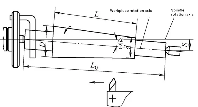
Fig. 7 Turning taper of automatic tool feeding of saddle
By offsetting the tailstock of the lathe laterally by a certain distance s, the axis of rotation of the workpiece intersects with the spindle axis of the lathe, creating an included angle equal to half the angle of the workpiece taper α/2.
As the bed saddle is fed parallel to the main axis, it results in a taper on the workpiece.
This method is suitable for workpieces with a small taper (less than 3°) and a long length.
3.1 Calculation of tailstock offset s
Tailstock offset S ≈ L0tan( α/ 2) = L0 (D-d) / (2L) or S = CL0 / 2, where,
- S is the tailstock offset (mm);
- D is the maximum cone diameter (mm);
- D is the minimum cone diameter (mm);
- L is the cone length (mm);
- L0 is the total length of the workpiece (mm);
- C is taper.
For instance, when machining a cylindrical taper workpiece between two centers, with the given dimensions: D = 80mm, d = 76mm, L = 600mm, and L0 = 1000mm, the offset of the tailstock (S) can be calculated as follows:
S = L0 × (D – d) / (2 × L) = 1000 × (80 – 76) / (2 × 600) = 3.3mm.
3.2 Offset measurement of tailstock
A dial indicator should be installed on the tool holder to measure the offset of the tailstock, as shown in Fig. 8.
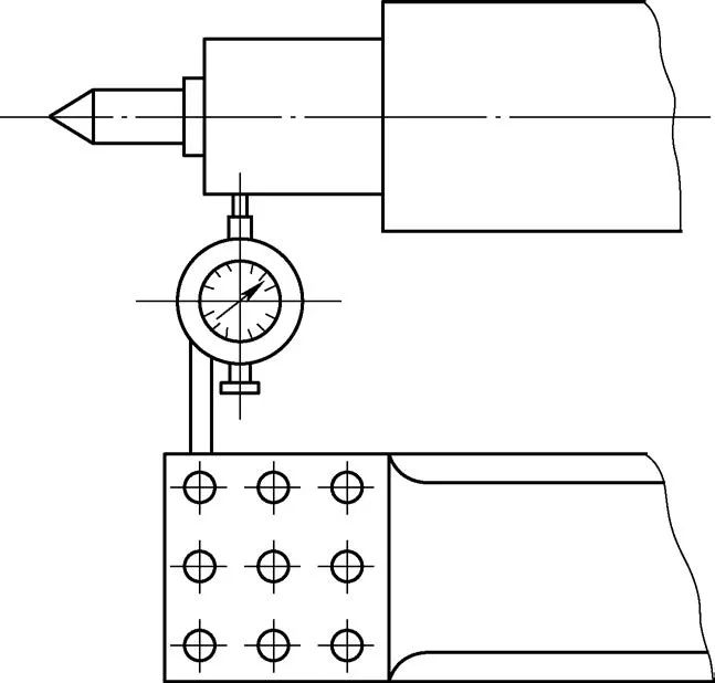
Figure 8 Offset measurement of tailstock
3.3 Turning steps
The bed saddle’s automatic tool feeding is used to machine a cone-shaped workpiece. The workpiece is clamped as shown in Fig. 9. The rough turning of the outer cone is depicted in Fig. 10, and the fine turning of the outer cone is shown in Fig. 11.

Fig. 9 Clamping of workpiece

Fig. 10 Rough outer cone

Fig. 11 Finish turning outer cone
3.4 Characteristics of turning outer cone with automatic tool feeding of bed saddle
- This method is suitable for machining outer conical workpieces with a small taper (less than 3°) and a long cone. However, it cannot be used for workpieces with a large taper due to the limitations of tailstock offset.
- By feeding the bed saddle longitudinally automatically, the surface roughness (Ra) is reduced and the workpiece’s surface quality is improved.
- The tip of the workpiece may become skewed in the center hole, resulting in uneven wear and poor contact.
- The workpiece is clamped with double apices, and the chicken heart clamp transmits power, making it impossible to machine both the inner cone and the overall outer cone.
4. Conclusion
The two methods of machining a cone described above utilize trigonometric function relationships for data calculation, and then adjust the cone’s half angle indirectly through the dial indicator, resulting in the machining of the outer cone and improved accuracy of the workpiece’s cone half angle.
These methods have practical significance in machining outer cones using standard machine tools.