Cracks were discovered on multiple parts of the gear reducer’s inner hole keyway hole wall and gear end face, in the circumferential direction, following gear grinding operations in a factory. The gear itself is made from 18CrNiMo7-6 material.
The production process: rough machining → carburizing and quenching+tempering → finishing (keyway opening, etc.).
In order to determine the cause of gear crack, a series of tests and analyses were carried out.
1. Test process and results
1.1 Macro inspection
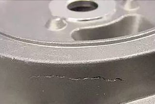
Cracks have been discovered on the outer circumference of the gear, as well as on the circumferential direction of the inner hole keyway hole wall and the end face. On some end face cracks, both sides were cocked up, as demonstrated in Figure 1.
Upon opening along the crack, the fracture morphology was observed. Most of the cracks exhibited a silver metallic luster of fine porcelain, and no previous fractures were identified. The root corner of the keyway was determined to be the source of the cracks.

Fig. 1 Gear Crack Location and Morphology
Obvious radial patterns and tear edges can be seen around the crack source, indicating high stress brittle fracture morphology, as shown in Figures 2 and 3.
The keyway appears rough, and there is a clear trace of wire cutting.

Fig. 2 Macro morphology of gear fracture

Fig. 3 Location of Gear Crack Source
1.2 Chemical composition inspection
The chemical composition of the gear was analyzed using an ICP (inductively coupled plasma) atomic emission spectrometer, and the results met the requirements of the EN 10084-2008 Technical Delivery Conditions for Carburizing Steel.
See Table 1 for the test results.
Table 1 Chemical Composition of Gear (Mass Fraction) (%)
| Component | C | S | P | Mn | Si | Cr | Ni | Mo |
| Standard requirements | 0.15~0.21 | ≤0.035 | 0.025 | 0.50-0.90 | 0.40 | 1.50~1.80 | 1.40~1.70 | 0.25-0.35 |
| Cracked gear | 0.18 | 0.002 | 0.016 | 0.76 | 0.23 | 1.68 | 1.62 | 0.27 |
1.3 Hardness and metallographic inspection
The gear’s carburized layer has a depth of approximately 1.58mm. The average hardness of the tooth surface is 725HV1, and the center’s hardness is 43.0HRC, which are all in accordance with the technical requirements of the drawing.
According to method B in GB/T 10561-2005 Determination of the Content of Non-metallic Inclusions in Steel – Micrographic Examination by Standard Rating Chart, all types of non-metallic inclusions are superior to grade 0.5.
According to GB/T6394-2017 Determination of Average Grain Size of Metals, the grain size is 6.5.
The gear’s carburized layer comprises a small amount of fine granular carbide, coarse acicular martensite, and more retained austenite.
Based on GB/T 25744-2010 Metallographic Examination of Carburizing, Quenching, and Tempering in Steel, the carbide is rated as Grade 1, martensite as Grade 5, and retained austenite as Grade 6, which do not meet the requirements of GB/T 3480.5-2008 Calculation of Bearing Capacity of Spur and Helical Gears – Part 5: Strength and Quality of Materials for carburized steel surface structure and retained austenite content, as demonstrated in Figure 4.
.jpg)
Fig. 4 Carburized layer structure (500 ×)
The specimen was obtained by cutting it from the source of the crack, polishing it, and then corroding it using a 4% nitric acid alcohol corrosion solution.
Upon microscopic examination, a white and bright layer was observed on the keyway’s surface, which appeared rough, with an irregular root and microcracks present.
Fig. 5 indicates that there is no carburization or decarburization on either side of the microcrack.
.jpg)
Fig. 5 Wire cutting white bright layer (500 ×)
2. Analysis and discussion
The reducer’s gear underwent testing, and the results indicated that its material composition, inclusion, grain size, hardness, and penetration depth all met the necessary requirements.
The main reasons behind gear cracking are as follows:
1)Fast wire cutting speed leads to a rough gear keyway, noticeable machining traces, and an irregular transition fillet shape. These factors aggravate stress concentration at the keyway, leading to the formation of a crack source. Subsequently, under the grinding stress, the crack gradually expands to become a gear crack.
Moreover, a high wire feeding speed causes the formation of a white layer on the keyway’s surface, which contains numerous microcracks. These microcracks, in turn, lead to cracks during subsequent processes.
During the manufacturing and use of parts with sharp concave corners, convex edges, or notches, significant stress concentration occurs at the transition of these areas. As a result, cracks may form.
Furthermore, rough tool marks on the machined surface caused by machine tool accuracy, tool edge shape, and operation during part processing also contribute to stress concentration and impair performance.
After inspection, it was discovered that the surface of the gear’s keyway was rough, with visible machining tool marks. The fillet shape at the keyway’s root was irregular, leading to a large concentration of stress.
2)The surface of the keyway had a white bright layer resulting from wire cutting. This layer is a quenching layer that contains a significant amount of residual austenite, an unstable structure that can convert into martensite and create substantial stress. When stress accumulates in the transition fillet, it results in an increase in stress concentration, leading to the formation of microcracks.
Additionally, the carburized layer’s martensite needle is thicker, and the residual austenite content is excessive, reducing the gear’s strength and increasing its brittleness.
Moreover, the retained austenite continues to transform into quenched martensite at room temperature, generating large residual internal stress and accelerating the growth of cracks.
3. Conclusions and Suggestions
Due to the high speed of gear wire cutting, the keyway surface becomes rough, the transition fillet’s shape becomes irregular, and a white bright layer is generated on the machined surface. This layer intensifies the stress concentration at the keyway, forming a crack source. Under the influence of grinding stress and residual stress, cracks gradually expand over time.
It is recommended to mill the keyway before carburizing. If wire cutting is required after carburizing, the wire speed should be controlled to ensure the proper shape of the transition fillet at the root of the keyway and improve the keyway’s processing quality. If the white bright layer cannot be avoided, it should be polished and removed manually after wire cutting.