Alkali-induced stress corrosion cracking, also known as “alkali embrittlement” or “alkali cracking,” has been documented in numerous literature sources. However, most of the research focuses on high temperature conditions, while there is relatively less research on the alkali embrittlement of stainless steel at medium and low temperatures.
Although failure due to alkali embrittlement can occur in high temperature environments, such failures at medium and low temperatures are relatively uncommon.
In a domestic nuclear power plant, the storage tank for the hydrogen generator was made of 316L austenitic stainless steel and contained KOH solution, with a working pressure of 700-800 kPa. After eight years of service, the lower head of the tank developed cracks.
A thorough physical and chemical inspection and analysis of the stress state in different areas of the tank were conducted to determine the cause of the cracking. Based on the results, suggestions for improvement were proposed.
1. Physical and chemical inspection
1.1 Macroscopic observation and penetrant testing
The leakage tank is composed of a cylinder and an elliptical head, which are welded together. The head can be divided into a straight edge section and a curved section, as depicted in Figure 1a.
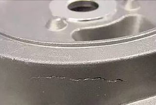
A through crack is present on the outer wall of the head and is located at the straight edge. The upper end of the crack is approximately 8 mm from the weld line, while the lower end is about 13 mm from the weld line. The total length of the crack is around 5 mm.

Liquid penetrant testing was performed on the tank and revealed that no additional cracks were present on the outer wall of the tank, apart from the through crack. However, multiple cracks were discovered on both sides of the inner wall near the weld. These cracks included axial cracks perpendicular to the weld and circumferential cracks parallel to the weld, as shown in Figure 1b.
The axial cracks were only present in the straight edge section of the head, within 13 mm from the weld line. They had a uniform circumferential distribution and different lengths. The upper end of the longer crack was 1-2 mm from the weld line, while the lower end was approximately 13 mm away. The upper end of the shorter crack was about 4 mm from the weld line, with the lower end approximately 10 mm away. This crack was classified as a Type A crack, while the through crack was also classified as a Type A crack.
The circumferential cracks were located on both sides of the weld, 1-3 mm from the weld line. Cracks on the cylinder side were classified as Class B1 cracks, and cracks on the head side were classified as Class B2 cracks.
The macroscopic diagram of the crack distribution in the leaking tank is shown in Figure 2.

1.2 Chemical composition analysis
The chemical composition of both the cylinder and head base metal was analyzed using a spark direct reading spectrometer. The results showed that both chemical compositions meet the requirements specified in the ASTM A473-2017 standard.
1.3 Metallographic inspection
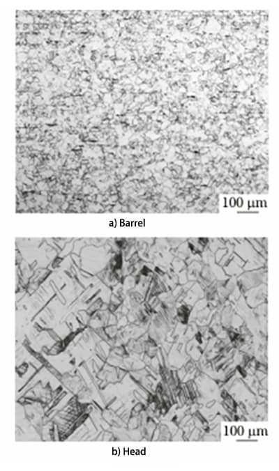
Samples were taken from the barrel and head base metal and subjected to metallographic inspection using an optical microscope. The microstructure of the tank base metal is depicted in Figure 3.
The microstructure of the barrel base metal was found to consist of austenite with a small amount of annealed twins, and had a grain size of grade 6. Meanwhile, the microstructure of the head base metal was composed of austenite with a significant amount of deformation twins and slip bands, and had a grain size of 3.5.
1.4 Hardness test
A digital Vickers hardness tester was used to measure the hardness of various parts of the tank. The results showed that the hardness of the barrel and head base metal was 165 HV and 248 HV, respectively.
The hardness of the weld, cylinder side heat affected zone, and head side heat affected zone was 171 HV, 188 HV, and 165 HV, respectively. The average thickness of the cylinder side and head side was 3.71 mm and 4.24 mm, respectively.
The cylinder was made of 316L steel in the normal solution annealed state. The hardness of 316L steel is not specified in the ASTM A473-2017 standard. However, according to the standard Cold Rolled Stainless Steel Plates and Strips (GB/T 3280-2015), the hardness of 316L steel should not exceed 220 HV.
The high hardness of the head, which is related to the presence of a significant amount of deformation twins and slip bands in the structure, can be attributed to the fact that it is 316L steel in a cold work-hardened state.
1.5 Analysis of crack morphology
1.5.1 Crack surface analysis

On the inner wall of the tank, cracks on the surface of Class A and Class B shall be sampled for analysis. The sample location is depicted in Figure 4.
After the sample is flattened, polished, and etched using an arc surface method, it is examined using an optical microscope. The microscopic morphology is illustrated in Figure 5.
It is apparent that both types of cracks extend in the direction of the crystal structure on the surface.

The central part of Type A crack is broad, while its two ends are narrow.
The heat-affected zone on the head side exhibits both a coarse-grain zone and a fine-grain zone, with a total length of approximately 4mm.
The heat-affected zone on the cylinder side only displays a coarse-grain zone, approximately 0.8mm long, with no fine-grain zone present.
The base metal on the head side shows a significant number of deformation twins and slip bands, characterized by high deformation and distortion. Static recrystallization occurs during the welding process due to heating.
As a result of the high temperature near the weld, grain growth occurs after recrystallization and forms a coarse-grain area.
Only static recrystallization takes place in the area distant from the weld, and the grain does not grow, resulting in a fine-grain area.
The base metal on the cylinder side is in a solution-annealed state, with limited deformation and distortion, and insufficient recrystallization driving force.
Due to the high temperature near the weld, grain growth takes place directly, forming a coarse-grain zone.
As the temperature in the area away from the weld is lower than the grain growth temperature, only recovery occurs without recrystallization, and there is no fine-grain area similar to that on the head side. As a result, it is not possible to directly determine the extent of the heat-affected zone.
Both the barrel and head parent materials are made of 316L stainless steel, with similar thermal conductivity. The extent of the heat-affected zones on both sides of the weld is roughly the same.
Based on the extent of the heat-affected zone on the head side, it is inferred that the width of the heat-affected zone on the barrel is approximately 4mm.
It is observed that one end of some Type A cracks is located in the heat-affected zone, while the other end is located in the straight edge section of the head, with the center situated in the straight edge section of the head.
The remaining part of Type A cracks is located at the straight edge of the head.
All Type B cracks are situated in the heat-affected zones on both sides of the weld.
1.5.2 Crack section analysis


Figures 6 and 7 depict the microstructures of the two types of cracks in the direction of the wall thickness.
Type A cracks run from the inner wall to the outer wall of the tank, following the crystal, with varying depths. The severe parts of these cracks nearly span the full wall thickness of the tank, with a bifurcated crack tip and grain boundary that is not sensitized. They possess typical characteristics of intergranular stress corrosion cracking.
Type B1 and B2 cracks are mainly found in the heat-affected zones on both sides of the weld. These cracks extend along the grain, with a bifurcated crack tip and grain boundary that is not sensitized, displaying typical characteristics of intergranular stress corrosion cracking.
The microhardness of Type A, B1, and B2 cracks is 242 HV, 171 HV, and 157 HV, respectively.
The sharp decrease in hardness in the B2 type crack zone is due to the occurrence of static recrystallization after the welding process, which transforms the original deformed austenite grains.

To gain further insights into the origin position of Type A crack on the inner wall of the tank, the depth of the crack was dissected and measured at the center and both sides along its length direction. The results are presented in Figure 8.
The deepest part of the crack along the wall thickness direction is found in the middle, indicating that the origin of the Type A crack lies in the center of its length direction and extends from the inner wall surface towards both sides.
1.6 Residual stress analysis

The Residual Stress Analyzer is utilized to assess the residual stress of the cylinder and head, with the weld serving as the boundary. The testing is conducted in two directions, 0° (parallel to the weld direction) and 90° (perpendicular to the weld direction), and the results are depicted in Figure 9.
The residual tensile stress zones on the cylinder side at 0° and 90° are approximately 20mm and 12mm, respectively, from the weld centerline. On the head side, the residual tensile stress zones at 0° and 90° directions are approximately 17mm and 15mm away from the weld centerline, respectively.
Type A and Type B cracks are situated within the residual tensile stress zones.
2. Comprehensive analysis
Type A and Type B cracks are found in the residual tensile stress zone of the tank, both running along the wall thickness from the inner to the outer wall in the direction of the crystal.
Type A cracks start in the base metal area of the head and spread out along the surface perpendicular to the weld on both sides.
Type B cracks are situated in the heat-affected zone on either side of the weld and extend parallel to the weld along the surface.
The head is manufactured through a cold stamping process.
The head’s straight edge is formed by flanging the edge of the original sheet inward, which results in significant plastic deformation and residual tensile stress.
Under the prolonged influence of the initial cold working residual stress, a temperature of 65-70℃, and the service conditions of a KOH alkaline solution, intergranular stress corrosion cracking perpendicular to the weld is generated.
The original residual stress disappears due to the recovery and recrystallization of austenite grains after welding in the heat-affected zone.
Welding residual tensile stress is produced in the heat-affected zone due to the cooling shrinkage of austenite grains. This stress is mainly perpendicular to the weld, and under the prolonged effect of the service conditions of the KOH alkali solution at 65-70℃, intergranular stress corrosion cracking parallel to the weld is generated.
The cracking mechanism of the tank can be explained by the membrane cracking theory of alkali-induced stress corrosion cracking.
In the KOH alkali solution environment, a passive film forms on the inner wall surface of the tank, but it breaks under the high residual tensile stress.
Once the passivation film breaks, it doesn’t immediately reform on the metal surface in the fracture area.
The bare metal then comes into contact with the KOH lye, and OH- concentrates in the surface fracture area, leading to a reaction with the bare metal.
The bare metal reacts with the concentrated lye to form a metal oxide film, but this film breaks again under stress, repeating the passivation-fracture cycle, causing the crack to continue to expand and extend. Eventually, the tank cracks and leaks.
3. Conclusions and Suggestions
(1) The circumferential and axial cracks on the inner wall of the storage tank are caused by alkali-induced stress corrosion cracking.
The circumferential cracks are mainly caused by welding residual tensile stress, while the axial cracks are mainly due to cold working residual tensile stress on the straight edge of the head.
(2) To avoid circumferential cracks, it is important to control welding heat input and reduce welding residual stress.
To prevent axial cracks, a stress relief process should be added after the cold forming of the head to reduce the residual stress of cold working.
(3) To ensure the safe operation of equipment, non-destructive testing measures such as penetrant testing should be strengthened during operation for added protection.