How to Adjust the Size of the Press Brake?
Adjusting the bending size involves adjusting the distance between the stop fingers on the press brake.
Rough and fine adjustments are made using the button located on the bottom right of the press brake machine.
To adjust the bending angle, or the depth of the bend (such as the V-opening), use the runner located on the right side of the angle, with a cutting depth of S≤100.
Instructions for using the press brake machine:
- Determine the bending force and V-groove opening size of the lower die, which can be calculated based on the plate thickness and folded plate length.
- Align the centers of the upper and lower molds and adjust the gap.
- Set the front and rear stop positions and processing flow, switching as necessary according to the adjustment switch.
- Place the workpiece in the center of the hydraulic press brake machine table for pressure measurement.
- Readjust the die clearance and adjust the upper die adjusting block if necessary.
- Ensure that all seals are properly sealed, and replace them promptly in case of leakage.
- The backgauge adjustment typically involves both electric quick adjustment and manual fine adjustment, using the same method as for plate shears.
- Press the foot switch to start bending. The machine will stop working when the foot is released.
How to Adjust the Angle of the Press Brake?
- Adjust the stroke of the oil cylinder and perform a pressure test after adjusting one side.
- Replace the press brake dies.
- Place some paper padding on the bottom die.
How to Compensate Deflection of Press Brake Machine?
To counteract the negative effects of ram deformation, it is necessary to compensate for the deflection deformation of the ram. This ensures the accuracy of the machined joint surface and improves the accuracy of the workpiece.
Compensation Modes for the Hydraulic Cylinder:
- Electro-hydraulic servo press brake machine + hydraulic deflection compensation
The hydraulic automatic deflection compensation mechanism of the worktable is composed of a group of oil cylinders installed in the lower workbench. The position and size of each compensation cylinder are designed based on the deflection compensation curve from finite element analysis of the sliding block and workbench.
Hydraulic compensation accomplishes bulge compensation through the relative displacement between the front, middle, and rear vertical plates. The bulge is achieved through the elastic deformation of the steel plate itself, allowing compensation to be adjusted within the elastic range of the worktable.
Mechanical Compensation Worktable Mode:
- Dual electric servo hybrid press brake + mechanical deflection compensation
The convex wedge block is made up of a group of convex wedge blocks with inclined planes. Each convex wedge is designed based on the deflection curve from finite element analysis of the sliding block and worktable.
The numerical control system calculates the required compensation amount based on the bending force during the workpiece bending (which causes deflection deformation of the sliding block and the vertical plate of the worktable), and automatically controls the relative movement of the convex wedge to effectively compensate for the deflection deformation of the sliding block and the vertical plate of the worktable, resulting in an ideal bent workpiece.
Mechanical deflection compensation accomplishes “pre-bulge” by controlling position. A group of wedges forms a curve that aligns with the actual deflection in the length direction of the workbench, ensuring consistency of the gap between the upper and lower molds during bending and the consistency of the angle of the bent workpiece in the length direction.
Advantages of Mechanical Compensation:
- Mechanical compensation can provide accurate deflection compensation along the full length of the workbench. It is long-lasting and stable, reducing the maintenance frequency (such as oil leakage) of hydraulic compensation and maintenance is free within the service life of the press brake.
- With many compensation points for mechanical deflection compensation, the bending machine can bend the workpiece in a linear compensation mode and improve the bending effect of the workpiece.
- Mechanical compensation uses a potentiometer to measure the return signal position, providing digital control as a numerical control axis, making the compensation value more accurate.
The Press Brake Can’t Go Up and Down. What’s the Matter?
The inability of the hydraulic press brake machine to move up and down may be due to the following reasons:
- Check if the electrical system is functioning normally;
- Check if the hydraulic valve is clogged;
- Check if the back pressure valve is properly adjusted;
- Check if the foot pedal is malfunctioning.
How to Bend an Arc With a Press Brake?
Bend an arc on the press brake machine. If an arc blade is not available, use the upper die with a small V-mouth.
First, draw a line and fold along the scribed line to form an arc.
Even without a mold, it is still possible, although it may be a bit more complicated.
Calculate the arc length, chord length, arc height, and center angle of the workpiece, and then scribe and divide based on these data. Control the stroke and pressure to fold the arc from both ends of the arc to the arc height and produce the desired arc shape.
Here are the specific steps:
1. As shown in the red circle in the figure, put the place where you want to bend the arc under the press brake machine.

2. Press the switch and the press brake start to move downward.

3. As shown in the red circle in the figure, after the press brake machine presses the iron sheet, the hand only needs to be lifted slightly so that an excessive angle will not be formed.

4. At this time, lift the press brake machine, send the iron sheet forward, repeat the above three steps, and repeat three times or more according to the size of the arc you want.

5. Here, we repeat three times to bend a semicircle arc.

6. As shown in the figure, a circular arc can be folded in this way, and the visible effect is good.

Comparison Between Grating Ruler and Magnetic Grating Ruler of Press Brake
Introduction to Grating Ruler
A grating ruler is a sensor that utilizes the principles of light interference and diffraction.
It is often used in the closed-loop servo system of NC machine tools and can detect linear or angular displacement. The output signal is a digital pulse, which offers a large detection range, high accuracy, and fast response speed.
Introduction to Magnetic Grating Ruler
A magnetic grating ruler is a sensor that uses magnetic poles as the principle.
The base ruler is a uniformly magnetized steel strip, and the S and N poles are evenly arranged on it. The changes in the S and N poles are detected by the reading head.
Analysis of Advantages and Disadvantages of Grating Ruler and Magnetic Grating Ruler
(1) Grating rulers have relatively high precision (± 0.005mm), but are highly susceptible to temperature changes (generally below 40°C), and have strict requirements for the surrounding environment with a relatively short service life.
(2) Magnetic grating rulers have relatively lower accuracy (± 0.01mm), but they have better resistance to water, oil stains, dust, and vibrations, and are more adaptable to the environment with a relatively longer service life.
In conclusion, magnetic grating rulers are more suitable for areas with high temperatures most of the year.
Up and Down Moving Type of Press Brake, Which Is Better?
The Amada RG series CNC press brake features a down-moving type design. It utilizes a central parallel pressurization mode, which is unique in the industry. The main oil cylinder is located at the center of the lower worktable, while both sides are equipped with auxiliary oil cylinders. This helps to address the deflection compensation problem commonly associated with up-moving press brakes.
The RG series is known for its convenient operation, high efficiency, and precision. It has become synonymous with press brake machines.
What Is the Problem That the Downward Speed of the Hydraulic Press Brake Suddenly Slows Down During Operation?
This is considered to be part of the normal “work progress.” There is no issue.
Normal Machine Operation:
After starting the oil pump motor for a few minutes, if there are no abnormalities, the machine can be started.
To do so, turn the change-over switch to the “jog” position, set the delay time to its minimum, and press the foot switch in the “down” direction. The ram will then rapidly drop.
Once the ram comes into contact with the travel switch, the time relay will cause the ram to stop moving after a certain distance.
If the ram needs to continue moving down, adjust the time relay to a longer setting, release the foot switch, and then press the foot switch in the “down” direction again.
To move the ram up, press the foot switch in the “up” direction. The ram will return to its starting position, stop, and remain there until it reaches the top dead center.
The Bending Angle of the Press Brake Is Different
If you’re able to adjust the depth normally and the angles on both sides are unequal, then follow these steps:
- Disconnect the connecting rod between the two cylinders.
- Adjust the depth of each side individually.
- Ensure that the two cylinders on both sides are consistent.
- Reconnect the connecting rod.
LIST OF HAZARD SOURCES AND RISK ASSESSMENT FORM OF PRESS BRAKE
| L: Possibility of accident | E: Frequency of exposure to hazardous environment | C: Consequences of accidents | |||
|---|---|---|---|---|---|
| Fractional value | Possibility of accident | Fractional value | Frequency | Fractional value | Consequence |
| 10 | It’s perfectly predictable | 10 | Continuous exposure | 100 | Catastrophe, and multiple deaths (10 or more) |
| 6 | Quite possible | 6 | Exposure during daily working hours | 40 | Disaster, several deaths (3-9 people) |
| 3 | Possible, but not often | 3 | Once a week, or accidental exposure | 15 | Very serious, 1-2 people died |
| 1 | Unlikely, completely unexpected | 2 | Monthly exposure | 7 | Serious serious injury and disability (disability level 1-4) |
| 0.5 | It’s impossible. It’s conceivable | 1 | Several exposures per year | 3 | Serious injury and disability (disability level 5-6) |
| 0.2 | Highly unlikely | 0.5 | Very rare exposure | 2 | Minor injury (disability level 7-10) |
| 0.1 | Practically impossible | 1 | Minor injury | ||
Note: D ≥ 0 is a major hazard source.
Refer to twenty injury types:
- 1. Object strike
- 2. Vehicle injury
- 3. Mechanical injury
- 4. Lifting injury
- 5. Electric shock
- 6. Drowning
- 7. Burning
- 8. Fire
- 9. Falling explosion
- 15. Gunpowder explosion
- 16. Boiler explosion
- 17. Container explosion
- 18. Other explosions
- 19. Poisoning asphyxia
- 20. Other injuries.
| No. | Activities | Description of equipment name, operation location, etc | Hazard source | Characteristics (possible consequences) | Risk evaluation | Risk level | |||
|---|---|---|---|---|---|---|---|---|---|
| L- score | E-score | C-score | D- score | ||||||
| 1 | Operation | During operation, maintenance or shutdown of equipment | Electrical circuit falling off and insulation damage | Get an electric shock | 1 | 10 | 7 | 70 | 4 |
| 2 | Operation | During operation, maintenance or shutdown of equipment | Short circuit heating and fire of electrical circuit | Fire | 1 | 10 | 7 | 70 | 4 |
| 3 | Replace abrasives | Operation and maintenance of equipment | Crush finger | Mechanical injury | 1 | 6 | 3 | 18 | 5 |
| 4 | Add hydraulic oil | Maintenance equipment | Replace hydraulic oil and drop from height | Fall from height | 1 | 1 | 3 | 3 | 5 |
| 5 | Check the oil pump | Operation and maintenance of equipment | High temperature scald of hydraulic oil tank | Scald | 1 | 3 | 2 | 6 | 5 |
| 6 | Cleaning equipment | Maintenance equipment | Equipment top cleaning drop | Fall from height | 1 | 3 | 3 | 9 | 5 |
| 7 | Feeding | Operating equipment | Put your hand into the grinder and hurt your finger | Mechanical injury | 1 | 6 | 7 | 42 | 4 |
| 8 | Feeding | Operating equipment | The material board scratched his hands and fell to hit his feet | Mechanical injury | 3 | 6 | 2 | 36 | 4 |
List of Minimum Bending Radius of Common Metal Materials
| No. | Material | Minimum bending radius |
|---|---|---|
| 1 | 08、08F、10、10F、DX2、 SPCC、 E1-T52、0Cr18Ni9、1cr18ni9、 1Cr18Ni9Ti、1100-H24、T2 | 0.4t |
| 2 | 15、20、Q235、Q235A、15F | 0.5t |
| 3 | 25、30、Q255 | 0.6t |
| 4 | 1Cr13、H62(M、Y、Y2、CR) | 0.8t |
| 5 | 45、50 | 1.0t |
| 6 | 55、60 | 1.5t |
| 7 | 65Mn、60SiMn、1Cr17Ni7-Y、1Cr17Ni7-DY、1Cr17Ni7-DY、SUS301、 0Cr18Ni9、 SUS302 | 2.0t |
How Many Press Brake Controllers Are There? How to Choose?
Types of CNC Press Brake Controllers
There are many different types of CNC press brake controllers, including the DA66t, DA58t, E530, E52s, etc., each with its own unique functions. These controllers can be compared to computers, such as Win7, Win8, MAC, etc., where the functions vary.
When choosing a controller, it’s important to consider the conditions of the workpiece that will be processed, such as the type of bending, 3D simulation, control accuracy, and complexity. Currently, the E21 system is commonly used for press brakes, and the E21s system is used for shearing machines.
The CNC system for hydraulic shears includes the DAC310 and DAC360, while the CNC system for the press brake machine includes popular models such as the DA41, DA52, DA53T, DA56, DA66t, and DA69t. These systems are widely used and are made by the brand DELEM from the Netherlands.
With recent advancements in press brakes, various other systems have become available, including the Cybelec Series from Germany, the Delem Series from the Netherlands, the ESA Series from Italy, the MD series from Hong Kong, and the SNC Series from Nanjing.
Choosing CNC Press Brake and Shear Controllers
Choosing the right controller from the various options can be challenging for many customers. To make the process easier, consider the following standards:
- The system should be easy to operate. The purpose of using a CNC press brake is to make the process more convenient and efficient. If the system design is complex and the operation is cumbersome, it may not be the right choice, even if it is otherwise excellent. This is because if employees struggle to operate the system, it will not perform to its full potential in terms of efficiency and accuracy. A good CNC system should be simple to operate, easy to learn, and straightforward to choose.
- The system should be stable. It’s important that the system is stable and reliable. You don’t want to encounter problems with the machine just a few days after purchasing it, as it will affect your mood and delay production. To determine stability, consider the following factors:
- Look at the product’s market reputation and maturity.
- Evaluate the system manufacturer’s experience and expertise.
- Check the manufacturer’s after-sales service response time.
A stable system produced by a senior automation manufacturer will be more reliable than a system developed by a less experienced team.
How to Choose Between Open Loop and Closed Loop Press Brake?
Closed Loop Control
Closed loop control is also referred to as a feedback control system. It operates by comparing the measured value of the system output with the desired value, generating a deviation signal, and using that signal to control and adjust the output so that it is close to the desired value.
For example, when driving, you have a preliminary perception of the direction you want to go. During the drive, you observe the actual direction of the car with your eyes, compare it to the desired direction, and make adjustments accordingly, eventually bringing the car’s direction close to the target direction. This forms a closed-loop control system.
Closed loop control systems offer high accuracy and fast response times because they take into account the performance of each part of the machine tool. However, because the closed-loop control system involves many elements, it is more complex and expensive than an open-loop system.
Open Loop Control
Open loop control, on the other hand, does not provide feedback on the current control results. An example of open loop control is throwing something – once it’s thrown, you can no longer control it. Similarly, in the open-loop system of a press brake machine, the accuracy of bending depends solely on the accuracy of each part of the machine. The system cannot compensate for changes in the bending process, resulting in lower bending accuracy. Any external disturbance to the machine tool will change its internal parameters, but the open-loop design is simpler and more stable, both for the initial machine tool installation and for subsequent maintenance.
Conclusion
In conclusion, when purchasing a press brake machine, if the buyer has high accuracy requirements and sufficient funds, it is recommended to buy a machine with a closed-loop system. If accuracy requirements are not as high, an open-loop system may be a better choice.
What Is a Three Cylinder Press Brake?
An additional auxiliary cylinder has been added to the original two cylinders in the ram to better reduce deformation over time. This improvement enhances the accuracy of the bending process, making it a new generation of equipment compared to the double cylinder press brake machine.
This design is particularly useful when working with large-scale bending machines, as its superior performance is more noticeable.
What Is a Four Cylinder Press Brake?
The four cylinder press brake machine has a single machine structure consisting of left and right integral welding frames and two connecting beams in the middle. The four oil cylinders are installed on the wallboard and rigidly connected to the ram.
The worktable is connected to the four wallboards through four adjustable wedges, and the integral ram, worktable, and assembled frame make up a four cylinder synchronous press brake machine that demands uniform load and high precision.
What Is the Difference Between Three Cylinder Press Brake and Two Cylinder Press Brake?
The three cylinder press brake has an additional auxiliary cylinder in the middle of the ram, which is beneficial for the bending length. In contrast, the double cylinder press brake has cylinders at both ends. If the length is long, the angles at both ends will be the same and the middle may sink a bit.
The three cylinder press brake is an updated version of the double cylinder press brake machine, with improved accuracy due to the addition of an auxiliary cylinder in the middle of the ram, reducing the risk of deformation over time. Its superior performance is particularly noticeable when working with large-scale press brake machines.
- The double cylinder press brake machine has steel on both sides for adjustment, but the ram may still deform over time. The three cylinder press brake machine has an auxiliary cylinder in the middle to prevent deformation and improve accuracy.
- It is recommended to use three cylinders for machines with a height of 4 meters or above. The three cylinders are stressed in the middle, resulting in better pressing angles. However, the disadvantage of the three cylinder press brake is the inconvenience of maintenance. On the other hand, the double cylinder press brake may have the same angles at both ends after a long time, resulting in a larger middle angle, but it is easier to maintain.
Why Can’t the Press Brake Machine Return?
Reasons for the CNC Press Brake Not Returning
- The machine cannot return to its starting position when not under load, which may be due to a parameter problem or a hydraulic failure.
- The machine cannot return to its starting position during processing, and the workpiece angle does not reach the set value.
- The machine cannot return to its starting position during processing, and the workpiece angle has exceeded the set value.
Measures
- Debug the Y-axis bending parameters
The bending parameters should be adjusted based on the actual situation. If the gain is too small, the slider may not fold or fold in place. If it is too large, the slider may shake. The parameters should be adjusted so that the slider does not shake during operation and the gain should be as large as possible.
Or, the left and right valve offsets may not be set correctly in the diagnostic program, causing the Y-axis to be too small to be in place or too large to be unloaded.
If it is a hydraulic failure, check the main pressure and verify if the PV valve S5 is always in the power-on position.
- The parameter gain of the Y-axis bending part may be set too small and can be increased as appropriate.
Or, the pressure may not be sufficient. Analyze the reasons for the insufficient pressure, whether it is due to the programming or the signal and hydraulic part.
The programming reasons mainly include die selection, plate thickness, material, workpiece length, bending mode, etc. The hydraulic reasons mainly include oil pump leaks, polluted or damaged proportional pressure valve, clogged filter element, or contaminated oil.
- Check the programmed and processed workpieces, mainly for programming and operation reasons.
What Are the Functions of Three Motors of Ordinary Press Brake Machine?
- The main oil pump motor transmits power.
- The upword fine-tune motor adjusts the cylinder stroke.
- The backgauge motor adjusts the movement of the backgauge.
What Are the Functions of the Three Relief Valves on the Press Brake?
The electromagnetic relief valve increases pressure. The electromagnetic unloading valve adjusts the pressure to prevent damage to the machine if the pressure is too high. The electromagnetic directional valve changes the direction of the oil circuit and controls the movement of the oil cylinder.
What if the Press Brake Doesn’t Go up When It Comes Down?
The oil return pipeline may be blocked or there may be a leak or lock in the hydraulic cylinder. Check if port B of the control valve is functioning normally or if the valve plug is not moving at all.
The Press Brake Is Normal up and Down, but It Is Not Pressurized!
Recently, many press brake users have reported that their machine is not generating enough pressure. This issue can occur when the machine runs empty but cannot generate enough force to bend the metal plate. Here are some possible causes and solutions for this issue:
- Check the electrical contactor of the press brake for loose connections or disconnections.
- Check the movement of the solenoid valve core and clean it if necessary. Make sure to re-install it in the correct orientation.
- Check the overflow valve for a large opening, excessive oil return, or blockages. Clean and adjust the valve accordingly.
- Check for internal leakage in the oil cylinder and replace the sealing ring if necessary. Make sure the stroke of both left and right cylinders are consistent.
- Check the spring of the large hydraulic control valve and replace if necessary.
If none of these solutions resolve the issue, it may be a problem with the oil pump, which would require professional maintenance.
- Check the motor and oil pump for proper operation and oil leaks.
- Check for blockages in the large hydraulic control. Step on the switch to generate pressure and check the oil return line.
- Check the indicator lights on the solenoid valves and use a screwdriver to check for magnetism.
- Check each valve for proper operation by poking it. Clean or replace if necessary.
By following these steps, you can determine the cause of the low pressure issue and resolve it effectively.
Where Does the Number of Backgauge Axis (X,Y,Z,R) Of Press Brake Refer To?
- X-axis controls the rear stop
- Y-axis controls the cylinder stroke
- Z-axis controls the left and right of the rear stop
- R-axis controls the up and down of the rear stop.
How Does the X-Axis of Press Brake Return to the Origin?
Under normal circumstances, the origin will be automatically found after the system has been powered off. The process of finding it is determined by the system’s settings.
Why the Y-Axis of Press Brake Does Not Return?
There is an issue with the grating ruler. Simply perform a check and press return and reset.
How Many Times to Bend a Large Arc and How to Calculate the Bending Angle?
1st method
As shown in the above figure: the plate thickness is T = 2mm, and the center angle is 90 °
1. First calculate the arc length:
arc length L = 90 ° × 3.14÷180° × center layer R59 = 92.632.
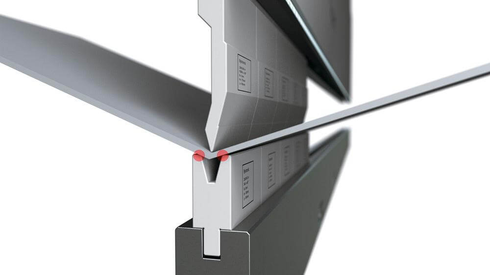
2. Select the bending die:
the upper die uses a acute punch and the lower die uses 8V die (when bending an arc, the minimum limit of V amplitude is 4T, which is normally 5-6t)
3. Calculate the feed rate per fold:
feed rate per fold = half of the V amplitude of the selected lower die
4. Calculate the number of folds:
number of folds = arc length L92.63 ÷ half of V amplitude 4mm = 23 folds
5. Calculate the positioning size of each fold:
after the positioning size of the first fold is calculated, the other folds decrease by 4mm (row from the inside to the outside when bending and arranging punches)
6. Finally, calculate the bending angle of each bend:
according to some algebraic calculation formulas of the triangle.
7. After the above calculation is correct, start to test bend with waste sheet metal, and process the product after testing the angle.
2nd method
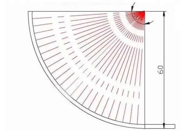
Let’s look at the picture below first.

The plate thickness is 2mm, the bending angle is 120 degrees, the external radius of bending is 30, the radius of the neutral layer is 29, and the arc length of the neutral layer is calculated for arc bending.
Therefore, the bending times and the bending angle of each bend are also calculated according to the arc length of the neutral layer
The distance between the neutral layer and the edge is half of the plate thickness.
In the figure above, how many bends are needed for arc bending, and what is the bending angle of each bend?
If we feed 2mm per bend.
- Bend times = arc length / 2mm = 30.37/2 = 15
- Bending angle
=180 – {(2 / arc length) x (180-bending angle)} = 180 – {(2 / 30.37) ×60} = 176
If we cannot measure the arc length during bending, we can also calculate it according to the following formula:
Bending angle = 180 – {(2 / 3.14×neutral layer radius) ×180} = 180 – {(2 / 3.14×29) ×180} = 176
If you want to bend 3mm everytime, replace 2 with 3 in the above formula.
Of course, the above formula is a theoretical calculation formula. In actual processing, it should be adjusted according to the results calculated by the above formula.
How to Adjust the Stroke of the Press Brake?
It depends on the size of your machine. For a small press brake machine, simply remove the synchronous shaft. For a large press brake, adjust the different cylinders through forward and reverse rotation of two separate motors, which must be performed by professionals. Improper adjustment can result in a broken synchronous shaft.

The Pressure at Both Ends of the Hydraulic Press Brake Is Not the Same. How to Adjust It?
- Power On and Oil Pump Start
- Turn on the power supply
- Turn on the key switch on the control panel
- Press the oil pump to start and listen for the rotation sound of the oil pump (the machine should not operate at this time)
- Stroke Adjustment
- Adjust the stroke before bending
- Ensure there is a plate thickness gap when the upper die of the press brake reaches the bottom to avoid damage to the die and machine
- Electric quick adjustment and manual fine adjustment are available for stroke adjustment
- Bottom Die V Opening Selection
- Select a notch 8 times the width of the plate thickness
- For a 4mm sheet metal, select a 32mm notch
- Rear Retaining Adjustment
- Electric quick adjustment and manual fine adjustment are available for rear retaining adjustment
- Bending Operation
- Press the foot switch to start bending
- The press brake can be released at any time
- If the pressure on both sides is different, adjust the up and down stroke screw on one side
- To adjust the height and pressure, remove the upper transmission shaft, adjust the stroke of the other oil cylinder based on one end, then connect the moving shaft
- If the adjustment keeps changing, dismantle and check the oil cylinder for loose nuts.
The Cylinder Stroke on Both Sides of the Press Brake Is Different. How to Adjust It?
If you have an ordinary press brake machine, you can adjust the synchronous shaft on the oil cylinder by standing on the machine. To do this, separate the shaft and adjust one end based on the other end. Then, reattach the synchronous shaft until the adjusted end matches the reference end.
How to Program CNC Press Brake?
It depends on the system you use. Generally, a simple numerical control system can be operated by setting the cylinder stroke and rear gauge size. If you need to bend multiple steps, you can set the size required for each step of bending according to the operation methods of different systems, and the system will run in a loop. If it is a fully CNC electro-hydraulic servo press brake, you need to set the selected upper and lower dies, material thickness, material, length, bending mode, angle, and rear gauge size. Depending on your needs, you can also set parameters such as speed change point position, return height, pressure holding time, and deflection compensation. Each system operates differently, so it cannot be generalized. I hope this information is helpful.
How to Adjust the Downward Speed of the Press Brake?
There are two travel switches located near the machine. One is used for height limiting and the other for pressure relief. If you want to slow down the machine, you can slightly decrease the setting of the pressure relief switch.
How to Calculate the Size and Angle of Sheet Metal Bending?
The expansion dimension is calculated based on the center layer. The length of the blank is related to the R angle of the die. After the actual folding, check the size of the part and modify the blanking size accordingly. The angle of bending is formed by three points, the points on both sides of the lower die shoulder and the outer point of the dead center, plus the rebound angle. The rebound angle for stainless steel is approximately 5 degrees.
In 90-degree sheet metal bending, the bending angle is calculated as a right angle bend minus 1.7 times the material thickness. For example, if the material is 1mm iron plate and the bending dimensions are 100mm and 50mm, the calculated expansion length is 100mm + 50mm – 1.7mm = 148.3mm. This 1.7 factor is sometimes adjusted slightly to 1.6 or 1.65, depending on the precision requirements. However, as each sheet metal factory may use slightly different bending dies, there may be some discrepancies, but these can usually be used without adjustments.
How to Calculate the Nominal Pressure Required by the Press Brake According to the Thickness and Length of the Steel Plate to Be Bent?
The calculation formula is P=650S^2*L/v.
P: Nominal pressure in kN. S: Plate thickness in mm. L: Bending length in m. V: Notch width in mm. Where V is 8-10 times the plate thickness.
This force is related to material strength, bending radius, V-groove width, and required bending length.
There are calculation formulas on the label of ordinary press brake machines. For ordinary low carbon steel, the formula is usually as follows:
Bending force = 65 × plate thickness^2 (in cm) × plate width (in cm) / (8 to 10 times the plate thickness in cm).
How to Calculate the Unfolded Dimension of Sheet Metal Bending?
The calculation method is divided into two cases, and the specific analysis is as follows:
- When the relative wall thickness of the R angle is very small, it is calculated according to the bending deduction. For example, 1.75mm is deducted from a 1mm thick sheet (generally determined by the specific experience of each company), 3.5mm is deducted from a 2mm thick sheet, etc.
- When the R angle is large, the median line (i.e., the center line of the inner and outer lines) is taken as the expansion dimension.
How Is the Bending Coefficient of Sheet Metal Calculated
The calculation formula is:
L = 0.5π × (R + K coefficient × T) × (θ / 90)
L: Length of the sheet metal after unfolding R: Inner radius of the bend T: Material thickness θ: Bending angle K coefficient: A constant determined by the position of the neutral bend line, which ranges from 0 to 1 and represents the material’s resistance to stretching during bending.
In sheet metal design, the commonly used sheet metal flattening calculation formula is based on the K coefficient. The relationship between the K coefficient and the Y coefficient is:
Y coefficient = (π / 2) × K coefficient.
What Is the Relationship Between Bending Factor and Plate Thickness, Bending Angle and Bending Radius?
The bending coefficient depends on various factors such as the plate thickness, bending angle, bending radius, upper and lower dies of the bending machine, and the length of the bending parts. Empirical values are usually used, as the conventional standard algorithm doesn’t take into account equipment wear. The coefficient changes with different plate thickness, bending angles, and materials.
For example, the coefficient of a 90-degree bend for 1mm cold-rolled sheet is 1.82mm, while it’s 3.5mm for 2mm cold-rolled sheet. The coefficient for 90 degrees is 1mm, 60 degrees is 1/2mm, and 45 degrees is 1/3mm. If the bending angle is less than 30 degrees, it may not be deducted or a 0.5mm deduction may be made, depending on the plate thickness.
The bending radius also affects the coefficient and is related to the press brake machine. A standard single V or double V can handle most cases, but if a customer needs a smaller or larger bending radius, it should be analyzed in detail. If the radius is too small, grooving can be used before bending. If the radius is too large, segmented bending or using a corresponding radius punch on the upper die can be employed.
Note that machinery and equipment play a significant role. A press brake that has been used for a long time can’t bend 1.5mm stainless steel over 1m with an 8mm lower die.
How to Calculate the Bending Coefficient of Sheet Stainless Steel?
The bending coefficient of cold-rolled steel sheet is closely related to the bending radius, and there are specific calculation formulas. The bending coefficient (z) of stainless steel plate is 0.2 to 0.3 times the thickness (T), generally 0.25 times the thickness (T).
| Thickness | Coefficient |
|---|---|
| 0.5 | 0.2 |
| 0.8 | 0.3-0.4 |
| 1 | 0.4 |
| 1.2 | 0.5 |
| 1.5 | 0.6 |
| 2 | 0.8 |
| 2.5 | 1.0 |
When t>3.0, the bending coefficient is 0.3 ~ 0.4t.
The bending coefficient of aluminum plate is 0.5T.
The bending coefficient of copper bar is 0.4t.
How to Calculate the Tolerance of Sheet Bending Machine?
Generally, the length of the thin plate increases by two plate thicknesses every time it is folded, although this can vary slightly depending on the equipment used. The wider the selected lower die, the larger the R angle and the greater the increase in length. It is best to test on the equipment used for more accurate results.
What Is the Reason Why the Middle of the Folded Workpiece Is Bent?
There are three reasons why the bending machine deviates from the center of the workpiece:
- This may be due to an unevenness between the upper punch and lower die. The quick clamp is adjusted to achieve the desired angle, but the straightness may not be sufficient.
- Similar to the first reason, this deviation can occur without compensation for deflection.
- To determine if the deviation is caused by a lack of parallelism between the upper ram and lower worktable, they can be marked and compared. Once the cause is identified, a solution can be found.
Why Can’t the Hydraulic Press Brake Go Up and Down?
The reasons for the hydraulic press brake not moving up and down may include:
- Checking if the electrical operation is functioning normally.
- Verifying if the hydraulic valve is clogged.
- Examining if the back pressure valve is correctly adjusted.
- Determining if the foot pedal has failed.
How Can the Angle of the Press Brake Be Adjusted if It Cannot Be Pressed at Right Angles
If you require a precise R angle when bending, it is recommended that you use a CNC press brake. Ordinary press brakes may result in an R angle due to lower machining accuracy. If a small angle deviation is acceptable, adjusting the pressure may help.
How to Fold Different Angles With a Press Brake?
If you want to avoid potential issues, you can opt for a CNC press brake which costs more. With this option, you can directly input the desired angle.
How to Disassemble the Oil Cylinder of the Press Brake?
To remove the oil cylinder from the press brake:
- Lower the ram to the bottom and remove the screw that lifts the oil cylinder.
- Raise the piston of the oil cylinder to its highest point, and shut off the machine.
- Use a forklift to support the bottom of the oil cylinder, then disconnect the oil pipe and screw. Remove the oil cylinder with the forklift and place it on the ground.
- First, remove the upper worm gear box. Then, unscrew the large nut of the oil cylinder and use a sledgehammer to remove the piston. (Please exercise caution when handling the oil cylinder and it is best to seek assistance from a professional.)
The Press Brake Cannot Be Started
If the CNC press brake machine experiences issues with its hydraulic system or phase sequence protection circuit, it may be due to incorrect three-phase electrical phase sequence. You can try changing the phase sequence to resolve the issue.
When preparing the press brake, it is important to follow these steps:
- Before starting the equipment, inspect the motor and power supply to ensure they are in good working condition.
- Verify that the punch and die of the press brake match and are securely in place for processing sheet metal.
- Check if the positioning device on the machine tool meets the standards for sheet metal processing.
- Ensure that the control parts and buttons of the press brake are in the correct position.
How to Eliminate the Bending Indentation of Stainless Steel Press Brake Die?
The outer side of the sheet metal during bending can be protected with a layer, such as plastic film. The inner side can have its bending angle reduced by using a smaller punch. Any dents formed during the process should be polished to eliminate the indentation.
How to Adjust the Downward Speed of the Press Brake Machine?
To adjust the speed during the bending process, you can modify the throttle valve on the hydraulic valve block. There are two options:
- You can pause briefly at the position where the workpiece is being bent.
- You can adjust the throttle valve to allow for a faster descent, meaning the downward speed is accelerated.
What’s Wrong With the Unstable Pressure of the Press Brake?
Reasons for pressure changes during press brake operation:
It is normal for pressure to fluctuate during operation. This is usually caused by incorrect pressure adjustment.
There are three factors to consider when adjusting pressure:
- Adjust and maintain pressure only when there is a load, not when the machine is idle.
- Allow enough time for pressure to be maintained. Do not release the pressure before the pointer is in place.
- Do not exceed the rated pressure. Exceeding the rated pressure can cause mechanical problems. If the adjusted pressure cannot be reached, this is normal. Some materials can be bent without much force, but applying the adjusted pressure is still necessary for smaller pieces.
Why Can’t the Press Brake Machine Rise?
If the press brake machine fails to rise, the first step is to check if the electrical operation is functioning normally. If it is, the cause is likely to be blockage in the rising overflow valve, which should be cleaned of any impurities or foreign matter.
Alternatively, the issue may be with a blocked directional valve, which also requires cleaning.
What About the Deformation of the Press Brake Ram?
Weld a horizontal bar and push it with screws.
How Does Press Brake Bend a Cone?
The bending angle of a cone is slightly greater than that of a cylinder. The bending angle of a cylinder is calculated as 180-360/n. For example, if 36 edges are folded, the bending angle would be 170 degrees.
How to Use Press Brake to Fold a Large Circular Arc?

(see attached figure)
To bend a large circular arc using a press brake machine, a custom set of circular arc punch and die must be made.
This mold can only accommodate a fixed radius, so there are certain requirements for the drawing.
Not all arc dimensions can be met with this mold, so sheet metal engineers must design the sheet metal parts based on the available die.
What’s the Matter With the Slow Down Speed of the Press Brake?
Typically, the press brake machine has a downstroke that slows down as it approaches the workpiece. Then, it begins bending at a slower speed when it is pressurized.
If the bending force is insufficient, causing difficulty in bending, the reason may lie in the material length, workpiece thickness, or machine pressure. These factors should be carefully considered.
What if the Downward Speed of the Press Brake Is Fast?
When using a press brake machine, it is important to determine if the speed is controlled by the valve diameter or the system, based on the type of machine.
Regardless of the type of machine, it is possible to slow down the speed by slightly locking the guide rail.
The Downward Speed of the Hydraulic Press Brake Becomes Slow and the Upward Jitter!
Checking for internal leaks in a press brake machine is relatively straightforward. Apply hydraulic pressure and after 15 minutes, if there is oil flowing into and returning through the cavity, the return pipe will be very hot.
To eliminate mechanical issues, push down the valve head of the change-over valve using a screwdriver to check for proper operation.
Additionally, inspect the pressure of the power inlet valve, which reduces pressure from high to low.
If mechanical reasons have been ruled out, the issue is likely with the valve group.
The Two Cylinders of the Press Brake Are Not Synchronized
To ensure proper operation of the press brake machine:
- Check the sliding slide for wear and adjust its tightness so that both sides are evenly tightened.
- Verify that the oil pipes of the two oil cylinders are connected in parallel and tighten the flow control valve. Remove any air from the oil cylinder by pressurizing and exhausting it.
- A one-way throttle valve is typically installed on the oil inlet (or return) of the two cylinders.
- If the original synchronization is no longer present, try adjusting one of the throttle valves to restore approximate synchronization of the two cylinders.
- If synchronization cannot be adjusted, there may be faults in two parts:
- The throttle valve may not be able to adjust the oil flow as needed, and a replacement throttle valve may be required.
- The speed may be too slow, requiring replacement of the piston seal in the cylinder.
What if the Workpiece Interferes With the Press Brake Machine?
When the standard punch cannot avoid a certain position, it is recommended to use a gooseneck punch, as shown in figure (1), to avoid the position.

However, if the gooseneck punch is still unable to avoid the position, it may be necessary to use an additional process. This can be done by first pressing a seal along the bending line, as shown in figure (2).

For improved bending results, it is recommended to bend the material to a certain angle to prevent blade collision, and then press the edge to 90 degrees, as shown in figure (3).

In general, the embossing process may be used for bending that cannot be completed in one operation. This allows for better formation of the bending line during the second bend, reducing the risk of bending deviation or poor control of the bending angle. However, this process should be avoided if possible, as it does not offer the same results as direct bending and may result in size and angle deviation.
The press brake can also be used to press the edge of the workpiece by first bending it to 30 degrees and then pressing it with a flat punch. However, it is generally recommended to avoid using the press brake to hem the edge, as the punch press typically produces better results.
During the bending process, the size of the workpiece and the bending knife can create interference, and for larger workpieces, the press brake itself may interfere with the bending. Therefore, it is important to consider ease of bending and feasibility in the design process.
Bending is a crucial process that greatly impacts the quality of the final product, and many quality issues arise from poor control of the bending size. Special attention should be paid to bending in the design process to ensure stability of quality during mass production.
The size of the bend is limited by the plate thickness and is related to the lower die. It is recommended to select a V opening with 6 times the plate thickness for the lower die to achieve the most consistent bending coefficient.
Die slots are generally classified based on the outer width of the slot, as shown in figure (4), and are referred to as #6 and #10 slots respectively.

However, when a small enough groove is selected for bending, indentation can easily occur. Generally, indentation below the #6 groove is obvious. On the one hand, it affects the appearance, and on the other hand, it can easily rust, so it should be taken into consideration in the design process.
As seen in the figure, for slot #10, the distance from the bending line to the positioning edge must be greater than 5.0mm before bending. For the #4 slot, which is the smallest tool slot, the distance from the bending line to the positioning edge should be greater than 2.0mm. The #4 slot is mostly used for thin plates (less than 1.2mm) because using it for thick plates may result in pressure being too high and the groove being too small, leading to the knife groove bursting.
When bending 1.0mm plate, the bending edge should be greater than 3.5mm to prevent indentation. For 1.5mm plate, the bending edge should be greater than 5.0mm, and for 3.0mm plate, the bending edge should be greater than 12mm. These considerations should be taken into account during the design process.
In the actual bending process, various problems may arise and the impact of bending on other processes should be considered. Specific problems should be analyzed and the process should be arranged accordingly. Suppliers may also manufacture special bending tools if necessary. However, if the shape of the tools is strange or the curvature is greater, it will inevitably affect the rigidity of the cutter and reduce its lifespan.
Can the Press Brake Machine Fold the U-Groove?
Absolutely, as show below:

Environmental Requirements of CNC Press Brake
The operating environment of a press brake is highly specific, and it also continuously affects the aging of the machine. The CNC press brake has certain temperature requirements for the working room. If the temperature is too high, it will cause overheating of the motor and operational stalling. If the temperature is too low, it will result in low oil temperature and insufficient pressure. Additionally, the CNC press brake produces a significant amount of metal dust during operation, and this dust will impact the efficiency of the hydraulic components and indirectly affect the stability of the CNC press brake machine.
What Happened to the Abnormal Noise of the Press Brake Oil Pump Motor?
- Insufficient hydraulic oil can cause abnormal sounds from the oil pump. Check the oil level.
- Dirty hydraulic oil that clogs the filter screen at the oil suction port can cause abnormal sounds from the oil pump and prevent the oil cylinder motor and other components from working. Clean the filter screen, filter the hydraulic oil, or replace the hydraulic oil to resolve this issue.
- If the oil pump is damaged, the inner surface of the stator of a vane pump will produce abnormal sounds, and if the plunger inside a plunger pump is damaged, it will produce abnormal sounds and vibrate severely. This can result in unstable pressure in the hydraulic system, which may be caused by hard objects in the hydraulic oil getting stuck in the pump.
What’s Wrong That the Press Brake Punch Can’t Lower to the Bottom?
Adjust the cylinder stroke by adjusting the upper and lower limits on the sidewall.
How to Select the Size of the Lower v Groove for Sheet Metal Bending According to the Plate Thickness
Sheet material: 1-3mm, the groove width should be 4-6 times the thickness of the material.
For thick plate: 4-10mm, the groove width should be 8-10 times the thickness of the material.
A smaller groove width results in a smaller R angle after bending and requires more bending pressure. Conversely, a larger groove width results in a larger R angle and requires less bending pressure.
The selection of the groove width should be based on the tonnage and processing requirements of the selected press brake machine, which is based on industry experience rather than industry standards.
How to Break the Lock of the Press Brake?
If the PLC is locked, it is likely that you will need to contact the manufacturer for unlocking it. The original factory should be able to provide this service. If not, changing the system can be problematic because the original parameter settings may not be compatible with the new system.
How to Solve the Problem That the Press Brake Pressurizes Too Slowly? How to Pressurize Quickly?
- Slow pressurization of the press brake can occur due to a blocked oil circuit, leading to slow pressure. To resolve this issue, the hydraulic system can be removed and cleaned to increase pressurization.
- The ram part of the press brake is composed of a ram, oil cylinder, and mechanical stop fine-tuning structure. The oil cylinders are fixed on the frame, the piston drives the ram up and down through hydraulic pressure, and the mechanical stop is controlled and adjusted by the numerical control system.
- The worktable part can be operated through the button box. The motor drives the retaining frame to move back and forth, and the distance is controlled by the NC system with a minimum reading of 0.01mm (there are travel switch limits at the front and rear positions).
- The machine has a mechanical synchronization mechanism consisting of a torsion shaft, swing arm, and joint bearing. This system has a simple structure, stable and reliable performance, and high synchronization accuracy. The mechanical stop is adjusted by the motor and controlled by the numerical control system.
- The material retaining mechanism uses motor drive to synchronously move the two screw rods through chain operation. The numerical control system controls the material retaining size.
What Determines the Sheet Metal Bend Radius?
The radius of sheet metal bending is determined by various factors such as the sheet metal thickness, material, radius of upper and lower bending dies, bending pressure, and working temperature. The bending pressure, which is only determined by the sheet metal thickness and the notch width of the lower bending die, affects the change in the bending radius. The influence of the bending radius can be stabilized by limiting relevant factors based on the requirements.
It has been observed that the thicker the material, the larger the bending radius. This is because thicker plates require greater bending pressure and a larger notch in the lower bending die. The material also has an effect on the bending radius, but it has little influence in practical use. Custom bending factor tables can be created for different materials.
The thicker the sheet metal, the more resistant it is to bending deformation, which requires adjusting the pressure. However, the bending pressure cannot be increased indefinitely and must be adjusted to an appropriate level. The bending pressure is directly proportional to the sheet metal thickness and inversely proportional to the notch width of the lower bending die.
In practice, the sheet metal thickness is set, and the notch width of the lower die is selected based on the thickness. Therefore, the bending pressure, which is determined by other factors, is constant, and the bending radius does not need to consider the pressure factor.
Stress Relief of Stainless Steel 304 After Bending
Stainless Steel 304 is a Japanese brand, which is equivalent to 00Cr19Ni10 in China. It is part of the Austenitic stainless steel family.
The stress relief treatment of Austenitic stainless steel is a heat treatment process that eliminates the residual stress that occurs after cold working or welding. The steel is typically heated to 300 to 350°C for tempering.
For steels that don’t have stabilizing elements such as Ti and Nb, the heating temperature should not exceed 450°C to avoid precipitation of chromium carbides and intergranular corrosion.
For ultra-low carbon and Ti and Nb alloyed stainless steels that have undergone cold working or welding, it is necessary to heat at 500 to 950°C, then cool slowly, to eliminate stress. This process can reduce the likelihood of intergranular corrosion and improve the steel’s resistance to stress corrosion.
So, if you want to relieve stress from 304, the ideal temperature range is between 300 to 350°C, with a general recommended time of 1.5 to 2.5 hours per 100mm of effective section.
Regarding your question about removing stress after bending, I don’t think that’s necessary. Bending doesn’t cause any structural changes in Austenitic stainless steel, and there is no residual stress left after deformation. You can straighten it without stress relief.
What Are the Corresponding Protective Devices of the Press Brake?
There are several safety protection measures for press brake machines, including safety light curtains, safety grating, and laser protection. However, the most commonly used is the safety light curtain protection device, due to its flexibility and ease of operation for various types of press brake machines.
How to Adjust CNC Press Brake?
1. Machine Adjustment:
To adjust the stroke distance of the ram according to the thickness of the folded plate and the V-shaped opening size of the lower die, press the up and down buttons on the electrical box to control the small motor forward and reverse to reach the control piston’s extension length. The stroke of the ram is controlled and there are indicators next to the oil cylinder. Note: the ram must be at the top dead center (i.e. pressing on the travel switch) for the adjustment to be effective.
2. Upper Limit of Ram Adjustment:
When the ram rises, it will touch the travel switch and stay at the required position, reducing the empty distance of the ram and improving productivity. In the ‘Continuous’ specification, a command for continuous action can also be issued.
3. Slow Action of the Ram Adjustment:
When the ram moves down, the lower limit block will touch the travel switch, causing the ram to move slowly.
4. Punch and Die Gap Adjustment:
Measure the gap between the punch and die when the lower part of the punch approaches the V-shape of the lower die, and then correct the lifting distance of the ram.
5. Workpiece Bending Angle Adjustment:
The ram and worktable of the machine may deflect during operation, causing the middle angle of the workpiece to be greater than the angle at both ends. Fine-tune the screws of the working panel to ensure the angle of the workpiece is consistent. This function has been adjusted at the factory and generally does not need further adjustment.
6. Bending Pressure Adjustment:
Check the table or calculate the tonnage pressure of the folded plate using the pressure formula, and then adjust the handwheel of the remote regulating valve to make the pressure slightly greater than the folded plate tonnage, reducing the unnecessary load on the machine.
7. Parallelism Adjustment between Ram Bottom and Worktable:
If it is found that the folding angles at both ends of the workpiece are inconsistent after using the machine for a while, adjust the adjusting block at the lower end of the oil cylinder to keep the bottom of the ram parallel to the worktable.
What Is the Reason for the Noise of Press Brake?
- Ensure the oil quality meets the requirements
- Ensure the filter screen is not blocked
- Vent the outlet oil pipe
- Verify the oil pump is installed correctly
- Inspect the oil pump for internal wear.
How to Solve the Oil Leakage of Oil Cylinder of the Press Brake?
Generally, the hydraulic cylinder is disassembled, and the sealing ring is replaced. The end covers at both ends of the hydraulic cylinder are usually installed in two ways. The larger hydraulic cylinders mostly use flange plates. To remove the cylinder cover, screw several bolts onto the middle cylinder block, remove the bolts, and slowly pull it out. For smaller hydraulic cylinders, the cylinder body and head are threaded, and the rotating end cover can be removed from the cylinder body. If you are not familiar with the hydraulic cylinder, it is advisable to have someone else handle it, as improper handling during disassembly and assembly can easily damage the sealing ring and internal surface.
How to Repair the Scratches on Mirror Stainless Steel?
If the mirror stainless steel plate is scratched, appropriate methods can be used to remedy it. As a manufacturer of stainless steel polished plates, customers often ask similar questions.
Generally, if the scratch is not deep, it can be smoothed during mirror polishing by slowing down the feed roller speed and lowering the grinding head.
There are two types of scratches on mirror stainless steel: those that occur before processing and those that occur after mirror processing.
If the scratch is of the first type, the severity of the scratch must be judged. If the scratch area and depth exceed the customer’s acceptance limit for the final product effect, then the qualified plates should be re-selected. It is important to judge whether the final finished products meet customer requirements before plate processing, as this can save time and money.
Spot scratches, regardless of their depth, can be repaired by argon arc welding and then polished by a polishing machine. After polishing, they can be processed twice (or more) by mirror polishing equipment, which can solve this problem.
Linear scratches, or scratches, are relatively difficult to handle. Shallow scratches can be solved by slowing down the feed roller speed and lowering the grinding head. Deep scratches are not easy to fix. It is recommended to avoid scratch areas during processing and cutting mirror panel materials.
Large area scratches can be divided into two types based on scratch depth, and the treatment method is the same as for spot scratches.
If the scratch is of the second type, it is more difficult to handle. It is recommended to reduce or avoid the possibility of scratches on the mirror panel by using protective film, packaging the panel with a wooden frame, padding cardboard or plastic plates on top and bottom, wrapping the entire panel with waterproof paper, and indicating “Protect the Panel, Do Not Scratch” on the panel or packaging surface.
The finished mirror stainless steel plate with scratches can be fixed using the above methods. If semi-finished products with a mirror surface have scratches, a variety of polishing equipment, such as a handheld polishing machine with replaceable polishing wheels, should be used for better repair results.
How Much Can the Bending Tolerance of the Press Brake Be Controlled?
The accuracy of a renowned press brake machine can be maintained within ±0.5mm, while that of a servo press brake is around ±0.1mm, which is equivalent to 10 wires.
What Is the Minimum Bending Size of the Press Brake?
The minimum bending dimensions of various types of press brakes are shown in the table below:
| Thickness | Bottom die(V) | Minimum dimension of the first bend | Minimum dimension of the second reverse bend |
|---|---|---|---|
| 0.5mm | 6 | 4mm | 4mm+t |
| 0.8mm | 6 | 4mm | 4mm+t |
| 1.0mm | 6 | 5mm | 5mm+t |
| 1.2mm | 8 | 5.5mm | 5.5mm+t |
| 1.5mm | 12 | 8.5mm | 8.5mm+t |
| 2.0mm | 16 | 11mm | 11mm+t |
| 2.3mm | 16 | 12mm | 12mm+t |
| 2.5mm | 20 | 14mm | 14mm+t |
| 3.0mm | 25 | 17.5mm | 17.5mm+t |
Where Is the Pressure Relief After Pressurization of the Press Brake Adjusted?
Generally, adjust the time of time relay.
How to Choose Electro-Hydraulic Servo Synchronous CNC Press Brake?
Electro-hydraulic servo synchronous CNC press brake is a new type of press brake machine. This guide will introduce the basics of selecting an appropriate press brake, and several factors to consider.
Steps:
- Distinguish between an electro-hydraulic servo press brake and a conventional press brake. The main difference is the presence of feedback closed loop and electro-hydraulic press brake compensation.
- Calculate the required tonnage based on the material and thickness of the metal plate to be processed. Tonnage refers to the maximum bending force of the press brake, not its weight.
- Determine the blade width, throat depth, and distance between uprights based on the length of the stainless steel and other plates to be processed.
- Choose a manufacturer or brand of electro-hydraulic synchronous press brake, taking into consideration the quality, price, and after-sales service.
- Customize additional functions as needed, such as axis number requirements, compensation type, laser test, and safety protection (laser protection or light curtain protection).
Notes:
- The safety protection options are laser protection and light curtain protection, with laser protection being a higher level device used in high-end machines.
- The number of axes should be determined based on the accuracy requirements of the workpiece, with more axes leading to higher positioning accuracy.
How to Fold a Semicircle With a Pres Brake?
If you want to achieve half-circle folding, you will need a dedicated half-circle mold. If you don’t have one, you can design and create both an upper mold and a lower mold.
How Is the Inner Radius of Sheet Metal Bending Determined?
The minimum bending radius must be taken into account in the design of the bend. For typical materials, the radius is equal to the thickness of the sheet. For materials with poor plasticity, the radius should be increased accordingly.
How to Calculate the Bending Radius of Sheet Metal?
What you need to know is the R value on the neutral axis. The neutral axis is inclined towards the inside. If rounded, it must be the inner R value.
Generally, the neutral axis of SPCC plate is 0.445t from the inside to the outside. The inner R angle cannot be calculated. This depends on your bending tool. Different bending tools have different inner R values, which can only be considered similar.
Bending tools can be divided into sharp punches and radius punches.
For precision sheet metal bending, the calculation can be done as follows after rounding: Inner Radius A + Inner Radius B + 0.35T = Unfolded Dimension C.

How to Set Bending Radius and Bending Deduction in Solidworks?
The bending radius of each material thickness varies, but the default radius in the system is set to 1mm. It is important to set the bend deduction manually each time. To calculate the data of each sheet metal, one can refer to the bending allowance table. However, it is important to note that these calculations require experience and knowledge of sheet metal processing technology.
The accuracy of the calculations from the bending coefficient table is not guaranteed. Only those with a good understanding of molds and the ability to handle various bends can accurately calculate the unfolding size. The software simulates the ideal constant thickness bending, but in reality, the thickness decreases during bending. The default radius for material thickness can either be set to 1 or 0.5, based on previous settings and may not be meaningful.
When designing sheet metal parts, the value should be set individually based on experience or by checking the bending coefficient table. The system will automatically default to the last set value.
The Most Complete Sheet Metal Bending Allowance Table
Common bending allowance table
| Material | Thickness | V slot | Angle | Bending allowance | |
|---|---|---|---|---|---|
| Steel plate, fingerprint resistant plate, aluminum zinc coated plate | 1 | 8(30°) | 30 | 0 | |
| 45 | 0.5 | ||||
| 60 | 1 | ||||
| 75 | 1.4 | ||||
| 7 | 90 | 1.8 | |||
| 105 | 1.2 | ||||
| 120 | 0.8 | ||||
| 135 | 0.5 | ||||
| 150 | 0.3 | ||||
| 165 | 0.2 | ||||
| 1.2 | 8(30°) | 30 | 0.2 | ||
| 45 | 0.7 | ||||
| 60 | 1.1 | ||||
| 75 | 1.7 | ||||
| 7 | 90 | 2 | |||
| 105 | 1.4 | ||||
| 120 | 1 | ||||
| 135 | 0.6 | ||||
| 150 | 0.4 | ||||
| 165 | 0.2 | ||||
| 1.5(actual 1.4) | 8(30°) | 30 | 0.5 | ||
| 45 | 0.9 | ||||
| 60 | 1.4 | ||||
| 75 | 1.9 | ||||
| 10 | 90 | 2.6 | |||
| 105 | 1.8 | ||||
| 120 | 1.2 | ||||
| 135 | 0.8 | ||||
| 150 | 0.5 | ||||
| 165 | 0.2 | ||||
| Steel plate | 2 | 12(30°) | 30 | 0.6 | |
| 45 | 1.3 | ||||
| 60 | 1.9 | ||||
| 75 | 2.5 | ||||
| 12 | 90 | 3.5 | |||
| 105 | 2.4 | ||||
| 120 | 1.6 | ||||
| 135 | 1.1 | ||||
| 150 | 0.7 | ||||
| 165 | 0.3 | ||||
| 2.5(actual 2.4) | 12(30°) | 30 | 1.2 | ||
| 45 | 1.8 | ||||
| 60 | 2.4 | ||||
| 75 | 3.2 | ||||
| 16 | 90 | 4.4 | |||
| Steel plate | 2.5(actual 2.4) | 16 | 105 | 3 | |
| 120 | 2.1 | ||||
| 135 | 1.3 | ||||
| 150 | 0.8 | ||||
| 165 | 0.4 | ||||
| 3(actual 2.9) | 57°die | 60 | 2.9 | ||
| 75 | 3.8 | ||||
| 18 | 90 | 5.2 | |||
| 105 | 3.6 | ||||
| 120 | 2.4 | ||||
| 135 | 1.6 | ||||
| 150 | 1 | ||||
| 165 | 0.5 | ||||
| Steel plate | 4(actual 3.9) | 25 | 90 | 6.7 | |
| 105 | 4.8 | ||||
| 120 | 3.3 | ||||
| 135 | 2.2 | ||||
| 150 | 1.3 | ||||
| 165 | 0.6 | ||||
| 4.5(actual 4.3) | 25 | 90 | 7.3 | ||
| 105 | 5.2 | ||||
| 120 | 3.5 | ||||
| 135 | 2.4 | ||||
| 150 | 1.4 | ||||
| 165 | 0.7 | ||||
| 5(actual 4.8) | 40 | 90 | 9 | ||
| 105 | 6.5 | ||||
| 120 | 4.3 | ||||
| 135 | 2.8 | ||||
| 150 | 1.7 | ||||
| 165 | 0.8 | ||||
| 6 | 40 | 90 | 10 | ||
| 105 | 7.4 | ||||
| 120 | 5 | ||||
| 135 | 3.3 | ||||
| 150 | 2 | ||||
| 165 | 0.9 | ||||
| Milled aluminum plate | 1.2 | 7 | 90 | 1.5 | |
| 1.5 | 10 | 90 | 2 | ||
| Steel plate, aluminum zinc coated plate | Bilayer 1.5 | 18 | 90 | Inner 2.6 | Outer 3.4 |
| Bilayer 2 | 25 | 90 | Inner 3.2 | Outer 4.1 | |
| PVC | 3 | 15(30°) | 90 | 5 | |
The bending allowance table is applicable to the corresponding material, material thickness and angle.
If the material thickness and angle in the table are not met, the following table can be used to calculate:
the bending allowance of the corresponding angle = material thickness * multiple of the corresponding angle 2.65-2.4
| Angle | Multiple of material thickness |
|---|---|
| 60 | 1 |
| 65 | 1.1 |
| 70 | 1.3 |
| 75 | 1.5 |
| 80 | 1.6 |
| 85 | 1.7 |
| 90 | 1.8 |
| 95 | 1.6 |
| 100 | 1.4 |
| 105 | 1.2 |
| 110 | 1.1 |
| 115 | 1 |
| 120 | 0.8 |
| 125 | 0.7 |
| 130 | 0.6 |
| 135 | 0.55 |
| 140 | 0.5 |
| 145 | 0.3 |
| 150 | 0.33 |
| 155 | 0.3 |
| 160 | 0.2 |
| 165 | 0.15 |
| 170 | 0.1 |
| 175 | 0.1 |
For example, the material thickness is 3, the material is ordinary steel, the bending angle is 95 degrees, and the corresponding bending coefficient = 3 * 1.6 = 4.8
The bending allowance table requires the non-right angle dimensions to be marked and measured as follows:

How to Set the K Factor, Bending Deduction, Bending Allowance and Bending Calculation in Solidworks? What’s Their Relationship?
The bending allowance table is a reference table that you create beforehand and insert into your drawings when designing sheet metal parts. It is automatically added based on the plate thickness.
The K factor is mainly used for non-90 degree bending or large arc bending, and it can be set based on the bend deduction of your plate as determined by your bending machine.
Bending deduction involves subtracting a dimension from each bend, which is based on the plate thickness and lower die width. For example, if you have a 2mm cold plate and a 16mm lower die, the bending deduction would be around 3.4mm. This can be set in the sheet metal options of the part you’re drawing or in the bending settings.
The K factor is not typically used, but it is essential for non-90 degree and large arc bending where the bending deduction may not be accurate. To determine the K factor, you can draw a right angle sheet metal part, set the correct bending deduction, and then measure the unfolded size after clicking “unfold.” Then, set a K factor, such as 0.25, and compare the expansion size with the previous measurement. If they’re the same, the K factor is correct. If not, adjust the K factor until the unfolded size matches the previous bend deduction. Once you have the correct K factor, write it down and use it for plates of the same thickness.
How Does the Press Brake Accurately Control the Bending Angle?
The travel controller can be installed.
What Is the Reason Why the Blade of Press Brake Can’t Rise?
Generally, a press brake is equipped with two or more overflow valves, which come in two types: system and back pressure. If you’re not sure, you can remove and clean both, but first make sure that the solenoid valve is energized. Don’t assume that the relays in the electrical cabinet aren’t working if you experience step-on and step-off issues. Check the hydraulic part as well.
Which Axes Do the 3 + 1 Axis and 4 + 1 Axis of the Press Brake Refer to Respectively?
3 + 1″ refers to two movements of the oil cylinders (2 axes), the back and forth movement of the rear stop (1 axis), and the addition of a crowning system (+1 axis). The crowning system allows the backgauge to adjust its position as the die is pressed down, thus improving product accuracy.
4 + 1″ includes one additional rear stop that can move up and down for positioning with a double axis linear guide rail. These advanced features come with a higher cost, as the press brake machines are equipped with precision components such as servo motors, ball screws, and linear guides.
What Does the Y Value Limit of Press Brake Mean?
The limit of stroke is related to the stroke switch. If it has been moved, you can adjust it accordingly. However, if it has not been moved, do not make any adjustments.
Function of Time Relay in Press Brake Circuit
The pressure holding time and unloading time are two separate functions. The pressure holding time relay activates when the ram reaches the bottom dead center to secure the desired bending angle of the workpiece. After the pressure is maintained, the unloading time switch is activated to reduce the return impact noise.
What Is the Difference Between Electro-Hydraulic Servo Press Brake and Torque Synchronous Press Brake?
Electro-Hydraulic Servo Press Brake
The main cylinders on both sides are controlled synchronously through hydraulic control systems such as proportional electro-hydraulic servo valves and grating rulers, which are independently regulated by CNC. Accurate data is fed back to ensure the precision of the ram operation.
Torque Synchronous Press Brake
A torsion shaft is used to connect the left and right swing rods, forming a torsion shaft forced synchronization mechanism to maintain the synchronized up and down movement of the oil cylinders on both sides.
What Hydraulic Pump Is Generally Used for Press Brake?
Generally, ordinary plunger pumps are used, and gear pumps are used by individual manufacturers.
How Do You Know What Material the Lower Die of the Press Brake Is?
The lower die is generally made of die steel. You can determine its hardness by using a hardness tester.
When the Press Brake Steps Up, It Cannot Stop and Automatically Slides Down
The small hydraulic control valve and safety valve may be leaking. If your press brake has been in use for several years, the aging of the sealing ring in the oil cylinder can result in internal leaks. Another factor to consider is whether the overflow valve of the machine has been moved. If it has been loosened to the end, it will automatically slide down. Additionally, check if the three-position, four-way directional valve is adjustable. If it is, inspect if there is a problem with the return trip. In general, machines that have been in use for a long time are mostly prone to internal leaks.
How to Understand the N + 1 Axis of Press Brake Machine?
- 3 + 1 axis: Y1,Y2, R and crowning axis
- 4 + 1 axis: Y1, Y2, X, R, Z1, Z2 and crowning axis
- 5 + 1 axis: Y1, Y2, X, R, Z1, Z2 and crowning axis
- 6 + 1 axis: Y1, Y2, X, R, Z1, Z2 and crowning axis
- 8 + 1 axis: Y1, Y2, X1, X2, R1, R2, Z1, Z2 and crowning axis
How to Change the Tool of Press Brake?
The method for replacing the top punch:
Place a piece of wood between the top punch and the bottom die and activate the machine to bring the punch close to the wood (to prevent the punch from falling).
Loosen the multiple tooling clamps on top of the punch and remove the punches.
Install the new punch, gently tighten the clamps, activate the machine to press the new punch onto the wood, and then fully tighten the clamps (to ensure a secure connection between the punch and clamps with no gap).
The method for replacing the bottom die:
Simply loosen the pressure block and then replace the die.
What Material Is Generally Used for Press Brake Dies? What Is the Hardness?
There are many kinds of materials, such as T10 or 42CrMo, and the hardness is generally about HRC45-50.
- Cr12Mo1V1, 42CrMo, 9CrSi, T10, 80#
- Quenching and hardening: HRC46 ° – 62 °
Do You Need to Grind the Top Punch of Press Brake?
The top punch of the press brake machine is specially heat-treated within 3mm of the cutting edge for increased hardness, but it will eventually wear out over time. Normal wear will result in a dulling and rounding of the tip. If multiple punches are worn simultaneously, there’s no immediate cause for concern, but if a single punch is partially worn, it’s recommended to have several punches machined together through annealing, grinding, and quenching. However, this is a difficult task and should not be attempted lightly.
How to Level the Tools of Press Brake?
You need to verify that the Y1 and Y2 values are equal and that the folded workpiece should only differ by a few threads. If they are different, adjust the Y1 and Y2 reference points and make fine adjustments. If they are equal, adjust the square bar with the value in the middle of the clamp and loosen the screw before making adjustments.
What Is the Problem That the Press Brake Tools Are Not in a Straight Line?
Generally, the straightness of the processing surface of the ram installed with the die is not high, or the die adjustment block may be deformed.
How to Repair the Crack of Stainless Steel Bending Tool?
The specific repair of tool cracks depends on the size of the cracks. If the crack is relatively shallow, a flat grinding can be used to remove one layer of the entire blade edge. However, if the crack is deep, using the grinding method may raise questions about whether the strength of the remaining part of the blade edge can withstand the bending pressure. Argon arc welding can also be used to repair the broken gap, but the hardness of the repair welding material may not be the same as the original material, affecting the tool’s performance.
How to Select the Material of Press Brake Die?
It is important to choose a material with high strength, toughness, and good wear resistance for cold working die steel. A good material choice is Cr12MoV, which has good service performance and process performance, but is relatively expensive. Another option is 42CrMo, which is an alloy quenched and tempered steel with high strength and toughness, and can work well at temperatures below 500 degrees.
What Is the Problem of Automatic Tool Drop of Ordinary Press Brake?
Generally, a leak in the hydraulic valve could be due to the age of your machine. If it has been used for several years, the sealing ring in the oil cylinder may have aged, causing leakage and slipping. Additionally, you can check if the hydraulic system is low on oil. If not, the problem could be with the software, which can be resolved by changing or reinstalling it.
Why Does the Press Brake Go Down Slowly?
The valve core is stuck. Repair it.
What Is the Difference Between the Acute Punch and Gooseneck Punch of Press Brake?
The difference between an acute punch and a gooseneck punch is that acute punches are typically used for bending angles of 45 degrees or less and for processing plate thicknesses of no more than 5mm. On the other hand, gooseneck punches are generally used for bending workpieces with a large radius. If you want to bend a workpiece with a smaller radius, you need to use an acute punch.
The Press Brake Tool Has Dents. How to Repair It?
It can be resolved by sending the lower die for processing and grinding the two R angles of the lower V groove using a grinder. Another solution is to purchase anti-indentation film and place it on the lower die during bending, which can also address the indentation issue.
What Is the Quenching Hardness of General Press Brake Die?
The heat treatment of the press brake die is usually quenched and tempered to a hardness of HRC38 to 42. The press brake die is not a blade and is processed with slow speed and high pressure. Having too high of a hardness can easily result in die fracture, so high hardness does not necessarily mean it is durable.
Calculation Formula of Press Brake Die Price
To calculate the cost of press brake tooling, you need to first determine the volume of the die based on its overall dimensions (or calculate it for a single piece if the volume is too small). Then, calculate the weight and use the process and materials to determine the price. The price of CNC press brake tooling is around 45 yuan per kilogram, while domestic press brake dies are priced at around 25 yuan per kilogram.
What Is the General Angle of the Press Brake Dies?
The common angles for the top punch of a press brake machine are typically 85, 86, or 88 degrees. Similarly, the common angles for the lower die groove of a press brake machine are typically 85, 86, or 88 degrees. The appropriate angle can also be selected based on the rebound angle of the material being bent.
How to Select Arc Radius Punch and Die of Press Brake?
If the top punch is made into an arc, then the V-shaped lower die can be used to bend an arc. It is also possible to make arcs on both the punch and die, but only one arc size can be bent in that case.
How to Calculate the Bending Angle of the Press Brake?
The bending angle of a press brake is determined through the numerical control level and depth positioning of the electro-hydraulic servo system (Y1 and Y2 axis). Generally, you only need to select the appropriate tool from the system’s tool library based on the drawing, fill in the material type, length, thickness, bending width, angle, and other parameters. The system will then automatically calculate the plate expansion dimension, R angle, required pressure, and bending depth.
To operate, simply feed the sheet and step on the foot switch. Higher-end systems allow for programming by graphics. The system will generate 2D or 3D section graphics of the product based on the input data, display the material and tool positions, and provide a solid drawing of the bending workpiece. The bending process can be simulated, and the operator can follow the display during the processing for a clear and safe experience.
What Are the Factors That Determine the Service Life of Press Brake Die?
The optimization of die structure is crucial for enhancing the maximum load capacity of the die and reducing the level of thermal stress.
The efficiency of changes in section size will directly impact the service life of the die.
What determines the service life of press brake dies?
Consider the potential defects in processing technology and the impact of load capacity during operation due to the quality of the die material, and take necessary measures to compensate for any shortcomings in the metallurgical quality, in order to improve the die’s service life.
The defects in the machining process, pre-treatment, forging, quenching, hardening, and surface treatment will have a significant impact on the die’s wear resistance, anti-chipping ability, and anti-fracture ability.
For example, issues such as rough die surfaces, residual marks from machining, micro cracks from EDM, surface carburization and decarburization during heat treatment will affect the load capacity and service life of the die.
The die’s accuracy and stiffness, lubrication conditions, pre-treatment status of the processed material, preheating and cooling conditions, and the surface quality state, material hardness, elongation, and other mechanical properties of the machined parts, as well as the dimensional accuracy of the machined parts, will all impact the die’s life.
These are the factors that affect the service life of press brake dies.
How to Select the Top Punch of the Press Brake?
The top punch options include 88°, 86°, 84°, 30° acute punch, and 25° acute punch, among others. There are no specific regulations for the top punch, but acute punches are typically used for bending thin plates, while 88° punches are used for thicker plates and 84° punches are used for grooved plates. The selection of the top punch also depends on the desired final shape of the bend.
In terms of selecting between a straight punch and a gooseneck punch, the standard is to avoid collision. If the opening distance of the type C workpiece is large, either a straight or gooseneck punch can be used, but if the opening distance is small, only a gooseneck punch can be used.
If the press brake has a bending simulation feature, it makes it easier to choose a punch. In general, a 88° punch is sufficient for 1.5mm plate thickness.
Golden Section Size of Press Brake Dies
The standard 835mm die segments are: 300mm, 200mm, 100mm, 100mm, 40mm, 50mm, 20mm, 15mm, and 10mm.
Anti-Rust Treatment of Press Brake Dies
Rusting of the molds is a major concern for the manufacturers. In this article, we’ll discuss effective ways to prevent mold rusting, such as avoiding placing the mold in humid environments, using rust inhibitors after cooling, and using long-term rust inhibitors.
Precaution 1: Avoid Wet Storage
Placing the mold in a wet environment for an extended period can lead to rusting, no matter how effective the rust inhibitor is. To prevent this, it’s important to store the mold in a dry and ventilated area.
Precaution 2: Use Rust Inhibitor After Cooling
Using rust inhibitors before the mold has cooled down can result in rusting within a few days. The mold will absorb the water from the rust inhibitor, causing rust. It’s best to wait for the mold to cool down naturally and then apply the rust inhibitor.
Precaution 3: Use Long-Term Rust Inhibitor
There are many rust inhibitors available on the market, including antirust oils and powders. However, a long-term rust inhibitor is a specialized mold rust inhibitor, with a general rust protection cycle of one to three years. It can effectively protect the factory’s molds and reduce unnecessary losses.
In conclusion, following these precautions can help prevent the rusting of molds and ensure the safety of the factory.
The Press Down Pressure of the Press Brake Machine Is Not Enough, but the Rising Pressure Is Normal
To eliminate the problem of overflow valve and pump, start by checking for internal leakage of the hydraulic cylinder. The method is as follows:
- Press the machine down until the workpiece can no longer be pressed.
- Remove the oil pipe in the lower chamber of the oil cylinder and continue to press down.
- Observe if there is still oil flowing from the oil cylinder.
- If there is no oil flow, it indicates that the oil cylinder is in good condition and the external fuel injection is not an issue.
- However, if there is oil leakage at a lower pressure, it is likely that the internal sealing of the oil cylinder has failed.
Note: Do not press the return button and ensure that the oil pipe is completely disconnected to determine if the leakage is from the oil cylinder or the solenoid valve.
Comparison Chart of Press Brake Die Combination