Preparation before running
a. Familiarize yourself with the manual content and understand the machine’s main structure, operation method, and safety maintenance precautions.
b. Clean the machine’s surface of antirust oil, which can be done with gasoline or kerosene, but not dissolving detergent.
c. Clean the oil tank before refueling. The oil tank must not have any impurities. Refill with new oil, YB (c) -N32 or YB (c) –N46 hydraulic oil, filtered with a fuel dispenser whose filtering accuracy is not less than 5 μm, until the oil level is above four-fifths of the position indicated by the level gauge. Mobil AFT-25 hydraulic oil has the best effect after repeated tests. YB-N32 anti-wear hydraulic oil is recommended at low temperatures (around 5 ℃) in winter. Allow the machine to idle for a period of time, and install a heater in the hydraulic system if necessary. The oil temperature in the hydraulic system under normal operation should not exceed 75 ℃. Install a cooler if the oil temperature is too high.
d. Add lubricating grease to all moving parts according to the manual. e. Turn on the power supply, set the electric cabinet switch to the “1” position, do not start the oil pump motor, and check whether the hydraulic valves and relevant electrical components operate normally according to various process specifications and operation modes.
Machine operation
(1) Press the motor start button to start the main motor, check whether the rotation direction of the motor is consistent with the rotation direction on the oil pump label, and verify the rotation direction of the motor by observing the coupling.
If it is not consistent, stop immediately.
When changing the motor direction, professionals must cut off the power supply and change the incoming line phase.
When there is air in the pipeline system, press the start and stop buttons alternately for several times. After the air is discharged, the oil pump can enter normal operation.
(2) The detailed operation of new product programming must be carried out after reading the electrical system operation manual and operation manual in detail.
Machine adjustment
The machine tool has been accurately adjusted and tested before leaving the factory. However, all adjustments may change during transportation. Therefore, the following checks must be made before formal use.
(1) Adjustment of blade clearance:
The blade clearance of the machine is automatically adjusted by the numerical control system. Whether the blade clearance is adjusted properly will directly affect the shear quality of the sheet metal and the service life of the blade.
In order to obtain a high-quality cutting end face, a reasonable blade gap must be selected according to the material to be cut. The following methods are recommended to adjust the blade clearance.
Low carbon steel with a tensile strength σB = 370-400 MPa and elongation δ= 35% is used as the adjustment benchmark, and the blade clearance is selected according to 8% of the plate thickness. For medium and high carbon steel with low elongation, the blade clearance value shall be greater than that of low carbon steel with an equal thickness.
When shearing stainless steel plate, the blade clearance depends on its elongation, and the blade for shearing stainless steel shall be used because the elongation of some stainless steel is higher than that of high carbon steel with the same strength.
Attention:
a) After the blade clearance is adjusted, the machine must run empty at least once before formal shearing.
b) When shearing plastic materials, the blade clearance should be slightly smaller; when shearing brittle materials, the blade gap should be slightly larger.
c) After adjusting the blade clearance every time, trial cutting must be carried out.
(2) Adjustment of shear angle:
The shearing angle of the machine is automatically adjusted by the numerical control system.
The shear angle can be changed by adjusting the amount of oil in the upper chamber of the auxiliary oil cylinder.
Increasing the shear angle makes the workpiece easier to deform, while reducing it makes it more likely to produce burrs.
Attention:
a) After each adjustment of the shearing angle, the machine must run empty at least once before formal shearing.
b) When cutting requirements are not high, the minimum width of the narrow material that can be cut should not be less than 3 times the plate thickness; otherwise, the blade is likely to be damaged.
c) To obtain smooth shear parts without distortion and deformation, the minimum shear plate width should be greater than 15 times the plate thickness, but not less than 80mm.
d) The larger the width of the shear sheet, the smaller the deformation.
(3) Removal and installation of blade

| No. | Name | No. | Name |
| 1 | Tool carrier | 5 | Pressing cylinder |
| 2 | Upper blade | 6 | Front guardrail |
| 3 | Lower blade | 7 | Cover plate |
| 4 | Worktable | 8 | Adjusting screw |
The standard configuration of the upper and lower blades of the machine is two pieces of knife splicing, which has the advantage of convenient grinding and does not require a special grinder.
The entire length of the upper and lower blades can be configured according to the needs of users.
a) Blade removal
Start the machine, adjust the blade clearance to a maximum value of 0.64mm, adjust the shear angle to 1.0°, make the tool holder run up and down for several cycles, close the machine tool, and remove the protective fence and cover plate of the pressing cylinder.
Remove the lower blade first:
Loosen all mounting screws of the two lower blades, hold one lower blade with a long wooden square at the back of the machine tool to prevent it from overturning backward, remove the screws on the blade, and pull out the blade from the side of the machine tool.
Remove the other blade in the same way.
Then remove the upper blade:
Loosen all mounting screws of the two upper blades, place two suitable wooden squares between one upper blade and the workbench, and secure the upper blade. Remove the screws on the blade, slowly loosen the wooden squares, and pull out the upper blade from the side of the machine tool.
Remove the other upper blade in the same way.
b) Blade installation
The order of installing the blade is the reverse of the order of removing the blade.
Install the upper blade first:
Insert two suitable wooden squares at one end between the tool holder and the workbench, insert an upper blade from that end, hold it with two wooden squares, and install the screws on the blade without tightening.
Then install another upper blade in the same way.
Use these two wooden squares to press an upper blade upward to make the upper blade fully close to the blade edge fitting surface of the tool holder.
Then tighten the screws on the blade from the knife joint to the edge in turn.
Tighten the screws of the blade on the other blade in the same way.
Then install the lower blade:
Insert two lower blades from both sides of the machine and hold the lower blade with a long wooden square at the back of the machine tool.
First, install all screws and then tighten the screws of the lower blade from the knife joint to both ends in turn.
After the upper and lower blades are installed, install the cover plate and protective fence in turn.
Attention:
a) When removing the blade, the blade is heavy and sharp. The operator must be very careful and wear gloves before operating.
b) The tightening force of the blade screw is 35N · M.
(4) Blade grinding
The blade must be ground regularly.
After the blade becomes blunt, if it continues to be used, the outer grain structure of the blade will be damaged due to excessive pressure, which will not only damage the machine but also result in poor shear quality.
After grinding the blade, the grains in the outer layer can be removed.
The upper and lower blades of the machine have four cutting edges. Grinding is required when the fillet radius of the blade is greater than 0.25mm.
The amount of one-sided grinding is 0.5mm, and the grinding allowance of each blade is 4mm (2mm on one side).
If the blade grinding of the normally used plate shears is arranged according to this method, the grinding amount will be the smallest, and the service life will be the longest.
(5) Adjustment of blade clearance uniformity
After the blade is ground or changed, the blade clearance uniformity must be rechecked and adjusted as follows:
a) Start the machine tool, adjust the shear angle to 0°, make the upper and lower blades parallel, and adjust the blade clearance to a maximum value of 0.64mm.
b) Turn off the oil pump and manually adjust the throttle valve to 120 to make the tool holder move down slowly until the upper and lower blades coincide for 1-2mm on the whole length.
In other words, close the throttle valve to ensure that the tool holder does not slide down.
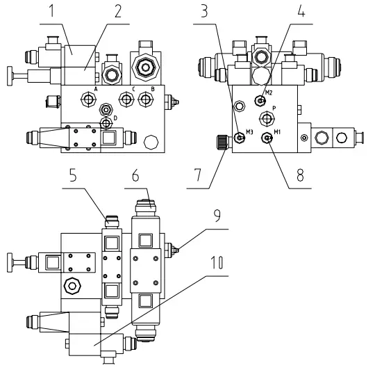
| No. | Item |
| 1 | Pressure cylinder control valve 140 |
| 2 | Pressure reducing valve of pressure cylinder 50 |
| 3 | Lower chamber support pressure measuring point |
| 4 | Pressure measuring point of pressure cylinder |
| 5 | Shear angle control valve 70 |
| 6 | Tool rest control valve 60 |
| 7 | Throttle valve 120 |
| 8 | Main pressure measuring point |
| 9 | Lower chamber support valve 80 |
| 10 | Main pressure control valve 20 / 30 |
c) Open the electrical cabinet door, press and hold the AC contactor 1KM2 that reduces the blade gap, monitor the actual value of the blade gap through the handwheel page, adjust the gap between the upper and lower blades to a minimum of 0.08mm, and close the electrical cabinet door.
d) Loosen the thrust screws and nuts on the two disc spring supports, loosen the nuts on the four spacer adjusting screws at the rear, and adjust the four adjusting screws to make the distance from both ends of the upper blade to both ends of the lower blade consistent (when adjusting one end, the upper and lower adjusting screws need to be adjusted at the same time).
Measure with a feeler gauge; the gap should be between 0.05mm and 0.1mm.
Then tighten the nuts on the four adjusting screws and the thrust screws and nuts on the two disc spring supports.

| No. | Item |
| 1 | Turbo-worm Reducer |
| 2 | Adjusting screw |
| 3 | Adjusting nut |
| 4 | Disc spring support |
| 5 | Gland |
e) Adjust the adjusting screw on the tool holder from left to right, and check the edge clearance with a 0.05mm and 0.1mm feeler gauge. Ensure that the 0.05mm feeler gauge can pass, but the 0.1mm feeler gauge cannot.
f) After shutdown, restart the machine, adjust the shear angle to the maximum, then close the oil pump. Adjust the throttle valve to 120 to make the tool holder lower slowly, and check whether the blade clearance of each section is the same as the originally set clearance value of the system.
If not, loosen the four adjusting screws on the rear side and adjust the blade clearance to the same value as the originally set clearance of the system.
g) Retighten the locking sleeve on the potentiometer and adjust the position of the gap adjustment travel switch.
6) Adjustment of rear stopper

| No. | Item |
| 1 | Lock nut |
| 2 | Adjusting screw |
| 3 | Screw M8 × 30(GB70-85) |
| 4 | Screw M8 × 35(GB85-88) Nut M8 (GB6170-86) |
a) Angle adjustment
The angle of the rear stop positioning surface must be consistent with the running angle of the tool holder. Otherwise, when the shear angle changes, the rear stop positioning surface will change, and the rear stop positioning will be inaccurate.
When checking the angle of the rear stop locating surface, place a dial indicator on the walls on both sides of the machine and point the head on the locating surface.
When the tool holder goes down, the reading change of the dial indicator should not be greater than 0.05mm.
If it is greater than 0.05mm, adjust the M8×30 (GB70-85) and M8×35 (GB85-88) screws.
b) Parallelism adjustment
Loosen the lock nut, turn the adjusting screw, measure the distance from both ends of the rear stop locating surface to the lower knife edge with a depth ruler, and then tighten the lock nut after the error does not exceed 0.05mm.
Try to cut the plate and check the parallelism. If there is any deviation, continue to adjust.
The distance from the middle of the rear stop locating surface to the lower knife edge should be slightly larger than that at both ends.
If the distance deviation from both ends of the rear stop locating surface to the lower knife edge is too large, loosen the screws supporting the transition plate connecting the servo motor. Then loosen the connecting screws between the support and the transition plate so that the synchronous toothed belt can be loosened.
Then rotate the ball screw on one side to make the distance from both ends of the rear stop locating surface to the lower knife edge almost the same.
Next, install the synchronous toothed belt, tighten the connecting screws, and tighten the synchronous toothed belt.
Then adjust the parallelism, and the adjustment method is the same as above.
(7) Pressure adjustment of hydraulic system:
The pressure values of the machine tool have been set according to the working specifications before leaving the factory.
The user does not need to adjust it themselves, but after the machine is overhauled or the hydraulic components are replaced, adjustment may be necessary.
If the user needs to adjust the system pressure, valve 30 should be adjusted according to the maximum working pressure (25MPa) of the hydraulic system.