1. Characteristics of welding direction and angle
1.1 Basic concepts
For gas metal arc welding, when the operator holds the welding gun with their right hand, it is typically performed from right to left. This is referred to as the “left welding method,” as the nozzle of the welding gun is at an obtuse angle (>90°) with the welding direction.
Conversely, when welding from left to right with an acute angle (<90°) between the nozzle of the welding gun and the welding direction, it is referred to as the “right welding method.
If the operator holds the welding gun with their left hand, the welding direction is reversed.
Figure 1 provides a visual representation of the left and right welding methods.
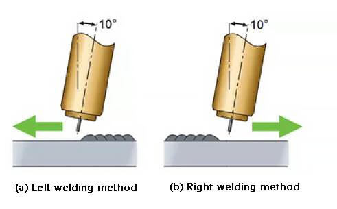
Fig. 1 Schematic diagram of left welding method and right welding method
The angle between the axis of the welding gun and the surface of the weldment is referred to as the “working angle.” In the plane where the axis of the welding gun and the welding direction are located, the angle between the axis of the welding gun and a straight line perpendicular to the welding direction is called the “walking angle.”
Figure 2 (a) depicts the working angle and walking angle for a fillet weld, while Figure 2 (b) illustrates the working angle and walking angle for a butt weld.
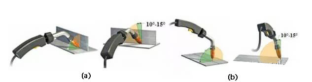
(a) Working angle and traveling angle of fillet weld (T-joint)
(b) Working angle and traveling angle of butt weld (butt joint)
Fig. 2 Schematic diagram of working angle and walking angle
Typically, the working angle for a fillet weld is 45°, while that of a butt weld is 90°.
The walking angle can be further classified into “rake angle” and “caster angle” based on the direction of welding. When welding in a rightward direction, it is referred to as the “caster angle,” and when welding in a leftward direction, it is known as the “rake angle.”
1.2 Effect on weld formation
When the direction and angle of welding vary, the behavior of the arc and weldment also changes.
During right welding, the majority of the arc acts directly on the weldment, while during left welding, the majority of the arc affects the liquid molten pool. As a result, under similar welding current, arc voltage, and welding speed, the width and depth of the weld may differ.
Figure 3 provides a visual representation of how the direction and angle of welding affects the formation of the weld.
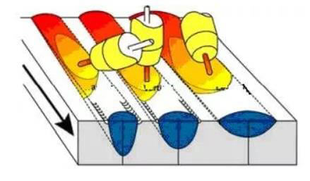
(a) Schematic diagram of the influence of butt weld welding direction and travel angle on weld formation
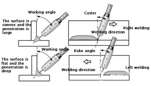
(b) Schematic diagram of influence of fillet weld welding direction and travel angle on weld formation
Fig. 3 Schematic diagram of welding direction and angle and its influence on weld formation
In addition to affecting the weld formation, the welding direction and walking angle also have an impact on the welder’s view of the weld pool, the size of spatter, and the effectiveness of gas shielding.
When welding with the left hand, the welder should observe the welding arc and pool from one side of the welding arc at an angle of 45° to 70°, which makes it easier to monitor the melting of the end of the welding wire and changes in the weld pool.
However, when welding in the right direction, the presence of the welding gun obstructs the welder’s line of sight, making it more challenging to perform the weld.
Figure 4 provides a schematic diagram of the optimal viewing angle for the welder during left welding (for a flat welding position).
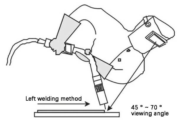
Fig. 4 Perspective of left welding (flat welding position) operator
When the walking angle is large, it becomes easier for air to be drawn into the weld, resulting in the formation of pores. To prevent this, the downward walking angle is typically set at 10° to 15°.
Additionally, the direction of welding also affects the size of spatter produced during the process. Left welding typically results in larger spatter, while right welding produces smaller spatter.
2. Application of welding direction and angle
Given the significant impact of the welding direction and angle on factors such as weld formation, spatter size, and gas shielding, different welding directions are utilized in actual welding production based on technical requirements and situational factors.
A table outlining the typical practical applications of various welding directions is provided for reference.
Table – Practical application of welding direction
| Application | Right welding method | Left welding method | |
|---|---|---|---|
| Flat welding | sheet | Not suitable, because large penetration is easy to burn through | Suitable, because the baking depth is shallow and the weld is flat. |
| plate | Suitable, because it can ensure good fusion | Not suitable, because of the shallow penetration, the penetration cannot be guaranteed. | |
| Transverse welding | Single pass welding | Not suitable because narrow and deep welds tend to form convex welds | Suitable, because it is easy to obtain wide and flat welds. |
| Multi pass welding | Suitable for backing welding and filling welding | Suitable for cover welding | |
| Vertical upward welding | arbitrarily | unsuited | fit |
| Vertical downward welding | arbitrarily | fit | unsuited |
3. Conclusion
3.1 The left welding method is characterized by shallow penetration and a wide weld bead, making it well-suited for welding thin plates. On the other hand, the right welding method is known for its deep penetration and narrow weld bead, making it ideal for welding medium and heavy plates.
3.2 A small walking angle results in a deep melting depth and effective protection of the molten pool. Conversely, a large walking angle leads to shallow penetration and poor protection of the weld pool. For optimal results, a walking angle of 10° to 15° is recommended to ensure good protection of the weld pool.