1. Introduction
In recent years, with the rapid growth of the manufacturing industry, the use of shearing machines as the primary processing equipment for sheet metal has become more widespread.
One of the most popular options among users is the hydraulic pendulum shearing machine, due to its simple structure, low failure rate, and excellent cutting quality.
To maximize the cutting quality of the hydraulic pendulum shearing machine, users are encouraged to have a comprehensive understanding of blade installation and adjustment.
While the blade adjustment method for the hydraulic pendulum shearing machine is outlined in various literature, obtaining satisfactory results in practice can be challenging due to factors such as the blade length, hardness, and the material and thickness of the plate being cut.
This article, based on an analysis of blade position, size, and installation for the hydraulic pendulum shearing machine, proposes that blade adjustment not only involves adjusting the blade height but also adapting the blade helix.
2. The installation requirements of the blade in the cutting process of the hydraulic pendulum shearing machine
As illustrated in Figure 1, the swinging tool carrier rotates around the o-point and cuts the sheet metal under the influence of the hydraulic cylinder.
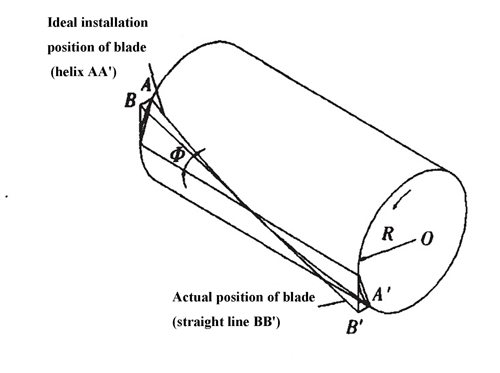
Fig. 1 The principle of shearing
To enable continuous cutting from right to left, the blade installed on the tool rest forms an angle X (i.e., cutting angle) with the worktable. The main requirements are as follows:
- Requirements for the front and back angle:
To ensure cutting quality, the vertical plane between the blade and worktable should always maintain a γ angle. However, because it is not possible to keep the blade on the same rotary cylindrical surface of the tool carrier, the front and back angles of the blade may change during the entire cutting process.
At the beginning of cutting, the front angle is large and the back angle is small due to the small turning radius (OA’) of the tool carrier. By contrast, at the end of shearing, the front angle is small and the back angle is large due to the increased turret turning radius (OB’).
- Preventing friction:
To avoid significant friction between the blade front and the plate being cut, the front face of the blade must always be within the arc of its motion path during the entire cutting process (from point c to point d).
- Clearance requirement:
To achieve a better quality of the sheared section, it is crucial to maintain a constant clearance △ between the blade and the plate being cut as much as possible (refer to Figure 2).
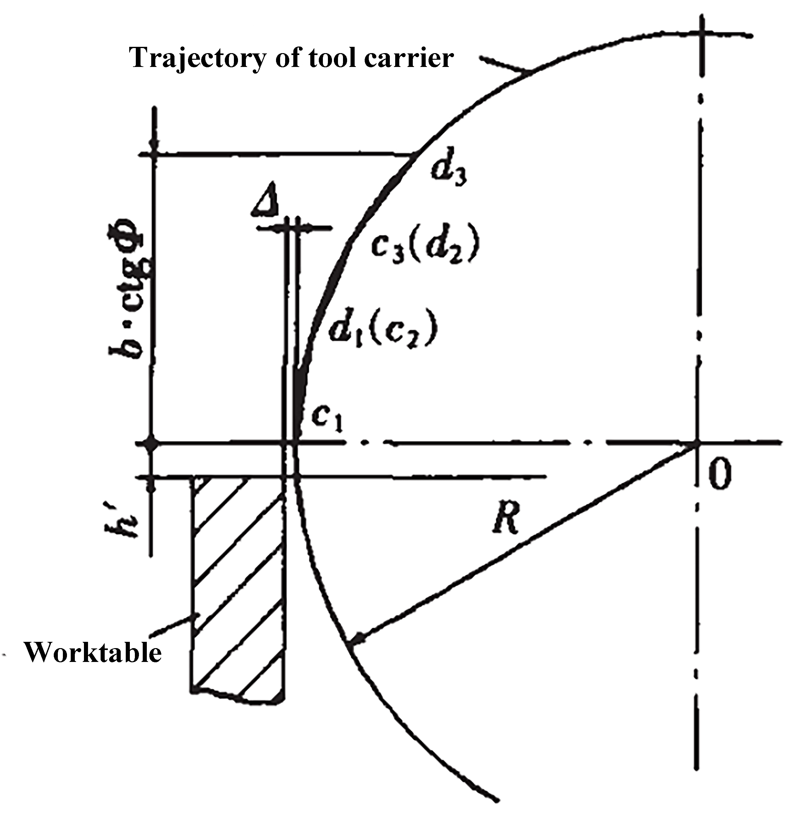
Fig. 2 Shearing clearance
The blade clearance should remain consistent along the entire length of the blade. Improper adjustment can increase wear and damage the blade, and may even cause the blade to collide with the table or cause the sheet metal to tip over.
To fulfill the above requirements, it is essential to adjust the front of the blade as close to a space spiral surface as possible, to ensure that the front and back angles remain constant during the cutting process.
3. General adjustment methods of hydraulic pendulum shearing machine blade
As it is impractical to adjust the front face of the blade to a space spiral surface, the requirement for a space curved surface is typically met by adjusting the thickness of the adjustment gasket between the blade and the tool carrier, as depicted in Figure 3.
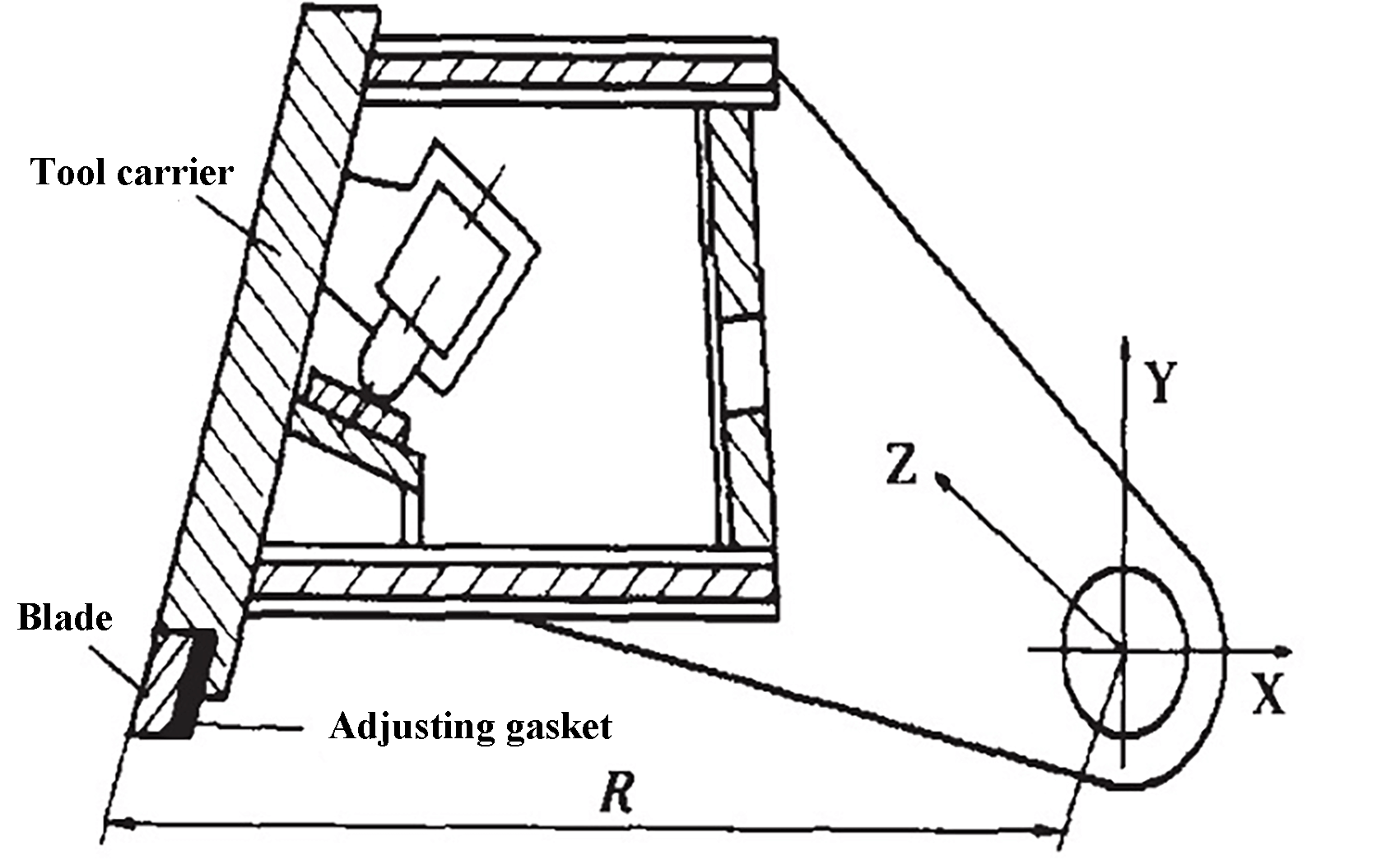
Fig. 3 The adjustment of blade
Despite its simplicity, the gasket thickness adjustment method still has some limitations. In order to meet the ideal blade installation requirements of space parallel curves, the blade must meet the following criteria:
x=R cosθ
y=R sinθ (1)
z=Rθ·ctg
Where:
- θ – rotation angle of the tool carrier around the axis
- Ф – shear angle
The blade should be a spatial helix, with its front surface being a cylindrical helix. However, using the simple gasket adjustment method can result in the following two issues:
- Gap issue:
A straightforward method for adjusting the gasket thickness is to align it along the length of the blade with a straight line, resulting in a blade that is a straight line, as illustrated in Figure 4.
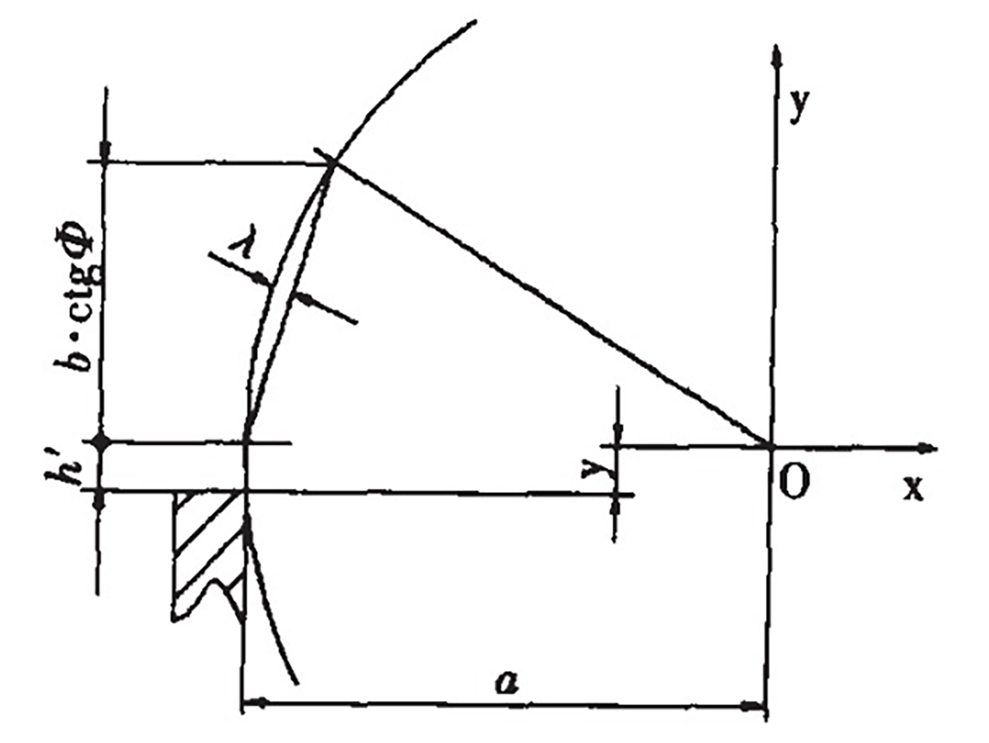
Fig. 4 The blade of the blade is a straight line.
This results in an actual gap between the blade and the plate being cut of △+. Because λ varies with the swinging angle θ of the tool holder, the gap between the blade and the plate being cut becomes a variable. The range of change for λ is as follows:
λ=R(1- cosβ) (2)
Where:
- β – swing angle of tool carrier from the beginning to the end of shearing
- β = arcsin( btgФ /R)
For example, if we calculate using QC12Y-6×200 (with R=469mm, Ф =1.5° and b=1600mm), the range of variation is approximately 1.8mm. If a 1100mm blade is used to adjust the gasket thickness, the range of variation is 0.88mm, which exceeds the recommended 0.5mm gap when cutting a 6mm steel plate.
It is evident that while the gasket thickness adjustment method is straightforward, it cannot ensure a constant clearance between the blade and the sheet metal throughout the shearing process, which negatively impacts the shearing quality.
- Front angle issue:
The gasket thickness adjustment method overlooks the requirement for the blade front to be a spiral surface and instead replaces it with a plane perpendicular to the workbench, which cannot guarantee the desired front angle (usually between 1.5° to 2° to ensure shearing quality and blade strength) during shearing.
For a blade with width W, the gap between the upper and lower edges and the ideal helical surface can be calculated as follows:
X’=R{1- cos[arcsin(y /R)} (3)
When substituting the relevant parameters of QC12Y-6×200 into equation (3), a value of X’ = 6.87mm is obtained and the maximum front angle is -arctan (x’/y’) = 4.91°. A negative value indicates a negative front angle.
Clearly, such a large range of variation in the front angle cannot guarantee the desired shearing quality.
4. Solutions
(1) Clearance Issue
The reason for the excessive shear clearance in the previous analysis and calculation is that only two straight lines were used to approximate the spiral line segment of the blade during the entire shearing process. By using multi-line segment approximation, the maximum gap can be reduced.
The blade of the QC12Y-6×200 is 1100mm, and the spacing between the locating holes is 200mm. If gaskets are used at each positioning hole for adjustment, the shear clearance variation, λ, can be calculated as 0.03mm using formula (2) and would meet the requirements. The thickness of the adjustment gasket can be determined by calculating the height of each straight line segment approaching the curved bow.
To meet the requirement of the front angle (γ = 1.5° to 2.0°), it is necessary to increase the distance, y, between the turret rotation axis and the worktable. Y is dependent on the turret rotation center and plate thickness. The shorter the turret turning radius, the thicker the sheet metal and the larger the Y value. These factors must be taken into consideration during shear design.
In practice, a gap adjustment device is often used to increase the shear gap, but this sacrifices the quality of the shear. Figure 5 shows the bevel gasket, and the bevel angle, n, is ground in the direction perpendicular to the worktable (a 1.5° angle is selected in the design, and the swing radius of the tool carrier can be slightly increased if it is small) to compensate for the error caused by using a plane perpendicular to the worktable to approximate the spiral surface.
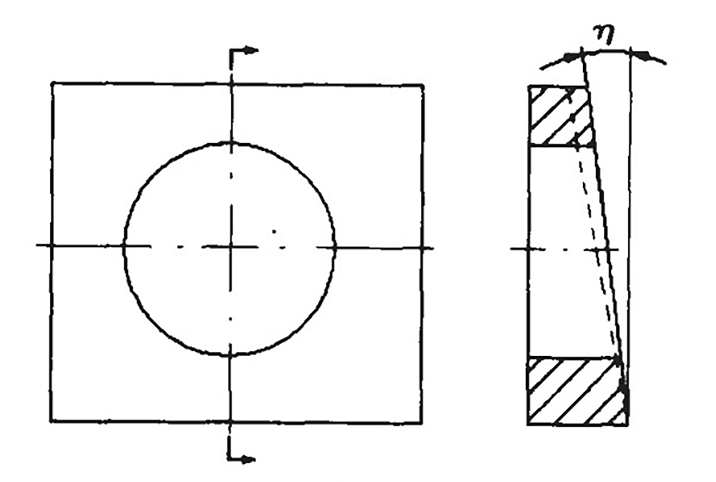
Fig. 5 Bevel gasket
To better conform to the requirements of the helical surface, when the tool holder is long, the surface that comes into contact with the blade can also be ground with an inclined plane of 1° along the length direction of the blade, as indicated by the dotted line in Figure 5. The longer the turret is, the more pronounced the effect becomes.
5. Practice results
The methods described above have been applied to the blade clearance adjustment of the QC12Y-6×3200 and Q12Y-12×2500 shears, as shown in Table 1. The data demonstrate that by using the inclined gasket and trimming the gasket at each mounting hole, the blade clearance can be reduced without undercutting during the actual shearing process, resulting in improved shearing quality.
It’s important to note that the experimental data in Table 1 includes the impact of blade shape errors on the minimum shear gap.
Table 1 The contrast of minimum shearing clearance between two adjusting methods of the blade / mm
| Model | General adjusting method | Use the inclined gasket and trim the gasket on each mounting hole |
| QC12Y—6 × 3200 | 0.62 | 0.36 |
| Q12Y—12 × 2500 | 1.0 | 0.65 |