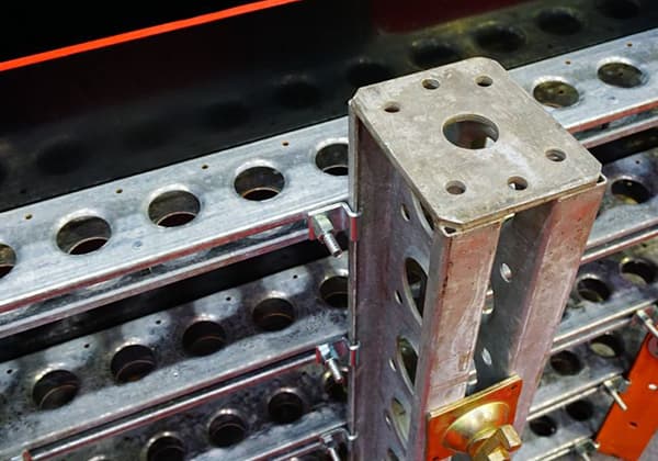
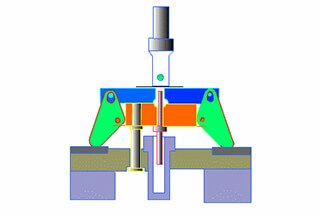
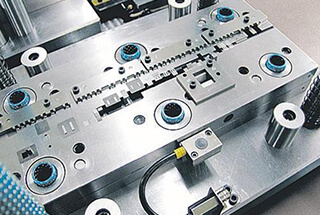
The CNC turret punch is widely used in the sheet metal processing industry due to its fast speed, high precision, strong versatility of molds, and its suitability for small batch and multi-variety product production.
However, it has very strict requirements for die precision and quality, making the selection and maintenance of turret punch tooling critical.
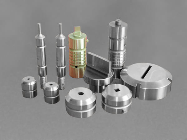
How to select turret punch tooling
Select the best die clearance
Die clearance refers to the difference in size between the edge of the punch and the die. It is influenced by various factors such as plate thickness, material, and process.
Choosing the appropriate die clearance is essential to achieve good punching quality, reduce burrs and collapse, maintain plate flatness, prevent material carrying, and prolong the life of the die.
If the gap is too large, the resulting workpiece will have a relatively large burr. On the other hand, if the clearance is too small, punching quality will be poor, the die will experience significant wear, and its service life will be significantly reduced.
Therefore, selecting a reasonable die clearance is beneficial in improving product quality, extending the life of the die, and reducing processing costs.
Typically, the corresponding die clearance is chosen based on the product drawing provided by the customer and compared with Table 1.
Table 1 Selection of die clearance
| Material | Min clearance | Best clearance | Max clearance |
| Red copper | 8%t | 12%t | 16%t |
| Brass | 6%t | 11%t | 16%t |
| Mild steel | 15%t | 20%t | 25%t |
| Aluminum (soft) | 10%t | 15%t | 20%t |
| Stainless steel | 20%t | 25%t | 30%t |
Note: If the plate thickness (t) exceeds 3.5mm, the maximum clearance is recommended. If the plate thickness (t) is less than 1.0mm, the minimum clearance is recommended.
Select reasonable die size and station
(1) The die station is typically selected based on the standard die punching size range indicated in Table 2.
Table 2 selection of punching size and die station
| Station | Size range / mm |
| A | φ1.6~12.7 |
| B | φ12.71~31.7 |
| C | φ31.71~50.8 |
| D | φ50.81~88.9 |
| E | φ88.91~114.3 |
(2) Special punches are necessary for punching holes in the range of φ0.8 to 1.6mm.
(3) The minimum dimension of the cutting edge of the die punch should be at least twice the thickness of the processed plate whenever possible.
(4) For the edge part of the punch, the ratio of the minimum radius to length should generally be no less than 1:10. For instance, for a rectangular punch with an edge length of 80mm, the edge width should be at least 8mm.
(5) The cutting edge of the die for processing thick plates should not have sharp corners or collapse angles that are prone to wear. Instead, sharp corners should be replaced with rounded corners that are greater than 1/4 of the plate thickness, whenever possible.
(6) When processing plates made of high chromium materials (such as 1Cr13 stainless steel and hot rolled plate), it is recommended to use imported high-speed tool steel as the die material.
(7) When processing thick plates, if the die size is close to the limit size of the station, it is recommended to replace the station with a higher one to ensure sufficient return force. For example, when processing the materials listed in Table 3, it is recommended to select a station one level larger than the corresponding station of the processing aperture.
Table 3 Selection of materials to be processed and die station
| Material | Plate thickness / mm | Aperture / mm |
| Mild steel | 6.0 | φ8.2~12.7/22.9~31.7 |
| 4.5 | φ11~12.7/30.6~31.7 | |
| Stainless steel | 4.0 | φ8.2~12.7/22.9~31.7 |
Arrange reasonable blanking process
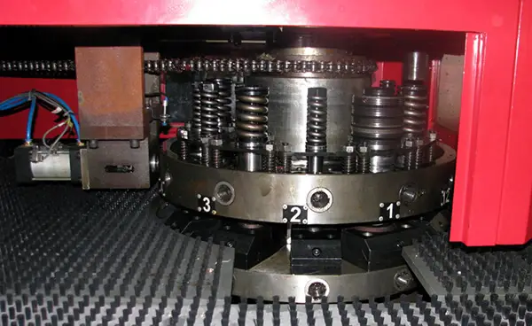
The blanking process of the CNC turret punch has a significant impact on production efficiency. An inefficient blanking process can result in the rejection of processed workpieces and even cause damage to molds and equipment.
Therefore, when arranging the blanking process, the following points should be taken into consideration:
(1) When the workpiece requires multiple processing, holes with the same processing properties should be processed in the same programming program as much as possible to prevent position offset and burr surface caused by workpiece displacement changes during processing.
(2) When programming the tool arrangement, the general principle of “small before large, round before square, and common mold before special mold” should be followed. The number of tools selected in the same program should be kept to a minimum.
Preferably, the cutter with the largest size should be selected to ensure that the total trimming length is not less than 1.5 times the length of the selected cutter. This will improve production efficiency and extend the life of the die.
(3) When the same workpiece requires different types of forming processing, care should be taken to adjust the tool path in programming so that different forming tools can be cross-processed as needed.
When machining workpieces with special tools, attention should be paid to the distance between two adjacent holes to prevent mutual damage caused by forming.
The center distance between two adjacent holes should be greater than or equal to the sum of the radius of the tool die sleeve and the radius of the first machined formed hole.
For example, the diameter of the upper die sleeve of the Type A hole is 26mm, and the outer diameter of the lower die is 25.4mm.
The diameter of the upper die sleeve of the Type B hole is 47.8mm, and the overall diameter of the lower die is 47.6mm.
If the first formed hole is formed upwards, the size of the above die sleeve is used for calculation. If it is formed downwards, the overall size of the lower die is used for calculation to avoid interference when processing two adjacent holes.
(4) When processing holes, it is important to place the mesh processing program before blanking and after other general holes to avoid plate deformation caused by mesh processing and displacement of other holes.
Additionally, if there is a line pressing process and other punching processes surrounding it, the line should be processed first, followed by the other holes, to prevent extrusion and deformation of other holes during line pressing.
When blanking the profile, the tool in the X direction should be placed on the surface, and the machining path should be kept close to the clamp along the Y axis.
(5) Care should be taken not to leave waste material on the table during tool arrangement, and full blanking or micro connection should be used to maintain the connection.
(6) If the workpiece has a rectangular hole or square hole structure, care should be taken to avoid single cutting edge when arranging the cutter.
When the process limits the SQ knife, the opposite edge of the rectangular hole can be punched with the OB knife or re knife, and then the appropriate SQ knife or re knife can be selected to punch the remaining part in the middle.
In this case, it is important to first punch the edge and then the middle to minimize contact and reduce tool wear through reasonable tool selection.
(7) When processing the workpiece, the reserved material should be taken into consideration. The reserved material should be chosen appropriately based on the material thickness and workpiece size, typically four connection points with a size of 0.2 to 0.3mm.
When there are special cutting tools or chamfers, it is important to increase the reserved material, generally to 0.3 to 0.4mm, and additional connection points can also be added.
(8) It is important to note that the width of the selected tool should be greater than the material thickness.
During continuous punching, the center distance between adjacent tools should be greater than half the length of the tool.
When the same straight edge needs to be arranged in sections during machining, care should be taken to select the same type of tool to avoid uneven guiding edge and step formation due to differences in upper and lower die clearance of the tool.
(9) The tool with a fixed position in the tool table should not be modified if possible and should only be edited if necessary.
If the tool with a fixed position needs to be installed at different angles, it should be edited on its original position, and there is no need to reinstall the tool in an empty position.
(10) When processing salad holes, the forming knife should be processed immediately after pre-punching to ensure concentricity.
As the forming cutter will squeeze and deform the sheet metal during machining, care should be taken to place the forming cutter before other cutters in the machining area.
When machining a large-sized circle or arc and there is no suitable tool for single punching, a smaller square cutter can be selected for step punching.
Attention should be paid to manually adjusting the spacing to set it in an appropriate range.
(11) When producing a batch of material in one set (nesting processing), most of them are processed by CO trimming with zero material. In case of small-scale production (i.e., when one workpiece is less than the entire sheet metal), priority should be given to full rows in the Y direction.
(12) When there are upward forming tools in special tools, meaning the lower die is a punch, other tools should be installed around the tool position as much as possible. Care should be taken when using special tools, such as stiffener tools. When arranging the tools, the line punching command should be selected to arrange the tools, and the manual mode should be used to set the gap, setting the gap parameter to a certain value.
However, due to the higher height of the punch compared to other tools, it can cause scratches on the sheet during processing.
Therefore, a stiffener should be arranged for final processing or listed as a separate program. When selecting special tools, consideration should be given to the processing direction.
Only tooth extraction and center punch among the existing special forming tools can be processed in both the upper and lower directions, salad holes, bumps, and crimping can be processed downwards, and stiffeners, louvers, and clamping slots can only be formed upwards.
Maintenance of turret punch tooling

Timely grinding can effectively prolong the service life of the die
If the workpiece experiences excessive burrs or abnormal noise during blanking, it may indicate that the die needs to be passivated. In this case, it is recommended to inspect both the punch and lower die.
If the edge of the workpiece forms an arc with a radius of approximately 0.1mm, it is necessary to perform grinding.
However, experience has shown that performing frequent micro-grinds, rather than waiting until it is absolutely necessary, can not only maintain good workpiece quality and reduce the blanking force, but also extend the service life of the die by more than double.
Eliminate and reduce sticking
During the pressure and heat of the blanking process, fine particles of the sheet metal can become bonded to the surface of the punch, leading to poor punching quality.
To remove the adhesive, it is recommended to grind the surface with a fine oilstone, making sure to keep the grinding direction consistent with the movement direction of the punch to avoid creating further adhesive buildup.
It is not advisable to use coarse gauze for polishing, as this can result in a rougher surface on the punch and increase the likelihood of the material sticking.
To minimize the formation of sticking materials, it is important to maintain a reasonable die clearance, employ good blanking practices, and ensure adequate sheet lubrication.
Lubrication is commonly used to prevent overheating and reduce friction.
