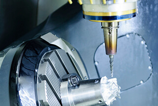
01 Steel milling
The machinability of steel is influenced by various factors such as alloying elements, heat treatment, and manufacturing processes like forging and casting.
When working with softer low-carbon steel, the primary challenge is the development of built-up edges and burrs on the workpiece.
When machining harder steel, it is crucial to carefully position the milling cutter in relation to the workpiece to prevent tool tipping.
To optimize the milling process for steel parts, it is advisable to adjust the position of the milling cutter to avoid thick chips when the tool is retracted.
Furthermore, it is important to consider dry cutting as an option, especially during rough machining, and avoid the use of cutting fluid.
02 Stainless steel milling
Stainless steel can be classified into three main types: ferritic/martensitic stainless steel, austenitic stainless steel, and duplex (austenitic/ferritic) stainless steel. Each type has its unique milling recommendations.
1) Milling of ferritic/martensitic stainless steel
Material classification: P5.x
The machinability of ferritic stainless steel is similar to that of low-alloy steel, so steel milling recommendations can be applied.
Martensitic stainless steel, on the other hand, has higher work hardening performance, and it requires a relatively high cutting force during machining.
To achieve the best results, it is essential to use the correct tool path and arc cutting method, and a higher cutting speed Vc to overcome the work hardening effect.
Greater safety can be ensured by using higher cutting speeds, tougher materials, and enhanced cutting edges.
2) Milling of austenitic and duplex stainless steel
Material classification: M1.x, M2.x and M3.x
The primary factors that contribute to wear when milling austenitic stainless steel and duplex stainless steel are cutting edge chipping caused by hot cracks, groove wear, and built-up edge/bonding.
In terms of parts, the primary concerns are burr formation and surface quality issues.
Hot crack
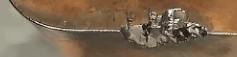
Blade cutting edge tipping
Burr formation and poor surface quality
Rough machining recommendations:
To prevent built-up edge, use a high cutting speed (Vc = 150-250 m/min).
To minimize hot cracking problems, opt for dry cutting instead of using cutting fluid.
Finish machining recommendations:
In order to enhance the surface quality of a material, it is often essential to use cutting fluid or oil mist lubrication/minimum lubrication. This technique results in fewer hot cracking problems during finishing as the heat generated in the cutting area is lower.
However, while working with cermet materials, the use of cutting fluid may not be necessary as a sufficiently good surface quality can be achieved without it.
It should be noted that if the feed fz is too low, the cutting edge might cut through the deformation-hardened zone, leading to more severe wear of the insert.
03 Cast iron milling
1) Gray cast iron
Material classification: K2.x
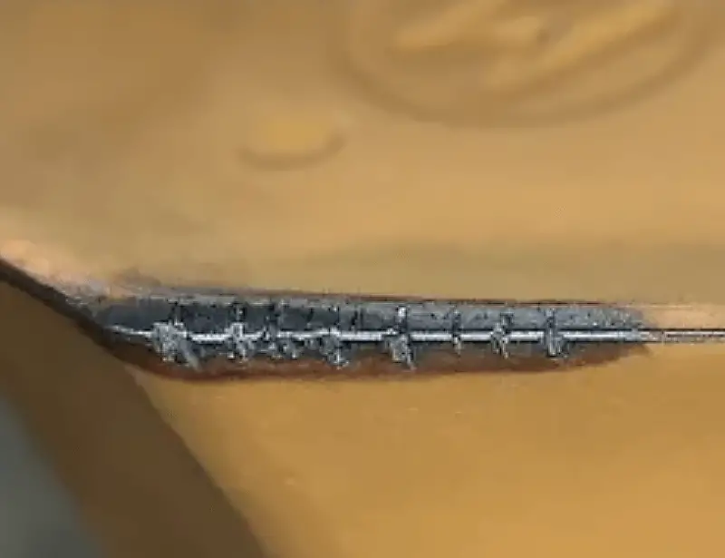
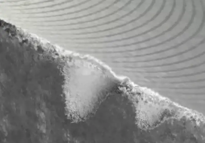
The primary factors that affect the wear of gray cast iron milling are abrasive/flank wear and hot cracking.
As for the components, the tipping of the workpiece and surface quality are the primary concerns.
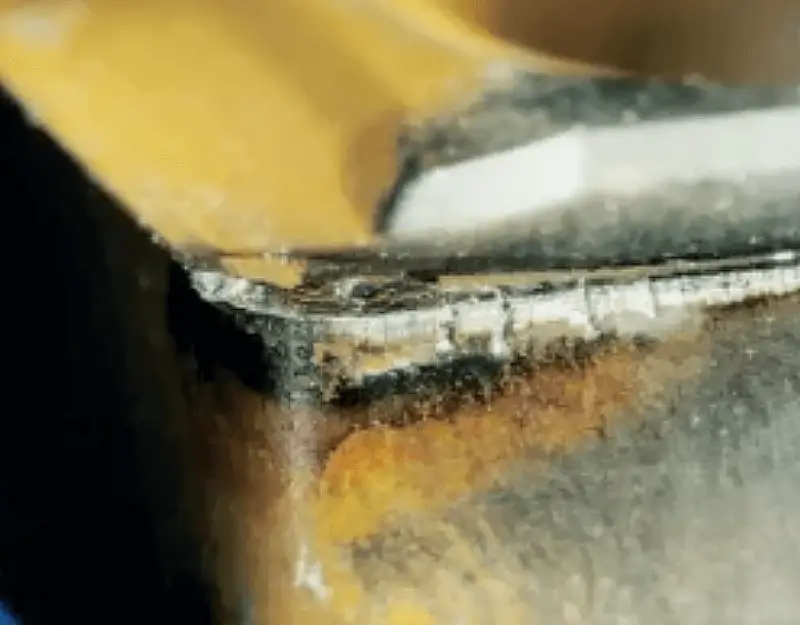
Typical blade wearing
Workpiece tipping
Rough machining recommendations:
(1) To minimize the occurrence of hot cracks, it is recommended to cut dry without using cutting fluid. Thick-coated carbide blades should be used.
(2) If the workpiece is tipping, several things can be done: check flank wear, reduce feed fz to decrease chip thickness, use a groove with a larger positive rake angle, and consider using a 65°/60°/45° milling cutter.
(3) If cutting fluid is necessary to avoid dust or other issues, a wet milling material should be chosen.
(4) Coated cemented carbide is typically the first choice, but ceramic materials can also be used. The cutting speed (Vc) should be set at a relatively high speed of 800-1000 m/min, but keep in mind that burrs on the workpiece can limit the cutting speed. Cutting fluid should not be used.
Finish machining recommendations:
(1) For cutting without the use of cutting fluid, it is recommended to use thin-coated or uncoated carbide blades.
(2) For high-speed finishing, CBN (cubic boron nitride) material can be utilized. Cutting fluid should not be used.
2) Ductile iron
Material classification: K3.x
(1) Ferritic ductile iron and ferritic/pearlitic ductile iron have similar machinability to low alloy steel. Therefore, when selecting tools, insert geometries, and materials, milling recommendations for steel materials should be used.
(2) Pearlitic ductile iron is more abrasive, so it is recommended to use cast iron materials.
(3) To ensure the best processing ability, the use of PVD coating materials and wet cutting is recommended.
3) Compacted Graphite Cast Iron (CGI)
Material classification: K4.x
The pearlite content is below 90%.
This type of compacted graphite iron (CGI), commonly used for milling processing, usually has a pearlite structure of around 80%. It is used in various components, including engine cylinder blocks, cylinder heads, and exhaust manifolds.
The recommended milling cutter guidelines for CGI are similar to those for machining gray cast iron. However, to reduce burrs formed on the parts, insert geometries with sharper cutting edges and larger positive rake angles should be chosen.
Arc milling can be an excellent alternative to traditional CGI cylinder boring.
4) Austempered ductile iron (ADI)
Material classification: K5.x
Rough machining is typically performed on materials in an unhardened state and can be compared to milling high-alloy steel.
On the other hand, finish machining is performed on hardened materials with high abrasiveness, similar to milling ISO H hardened steel. Therefore, materials with greater resistance to abrasive wear are preferred.
When machining ADI, tool life is reduced by approximately 40% compared to NCI, and cutting force is increased by roughly 40%.
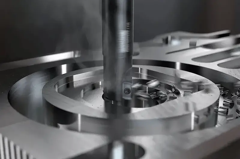
04 Milling of non-ferrous metal materials
Non-ferrous metal materials include not only aluminum alloys, but also magnesium, copper, and zinc-based alloys.
Related reading: Ferrous vs Non-ferrous Metals
Machinability is primarily determined by the variation in silicon content.
The most prevalent type is hypoeutectic aluminum-silicon alloy, which has a silicon content of less than 13%.
Aluminum alloy with silicon content less than 13%
Material classification: N1.1-3
The main criterion for wear is the buildup of edge/bonding on the cutting edge, which causes problems in surface quality and burr formation.
To avoid leaving scratches on the surface of the part, good chip formation and removal are essential. Here are some suggestions:
- The use of PCD-tipped inserts with sharp, polished cutting edges can ensure good chip-breaking ability and prevent the buildup of edges.
- Choose an insert geometry with sharp cutting edges and a positive rake angle.
- When machining aluminum alloys, cutting fluid should always be used to avoid material sticking to the blade’s cutting edge and to improve surface quality. The recommended concentration of the cutting fluid depends on the silicon content of the alloy. For silicon content <8%, use a cutting fluid with a concentration of 5%. For silicon content between 8-12%, use a cutting fluid with a concentration of 10%. For silicon content >12%, use a cutting fluid with a concentration of 15%.
- Higher cutting speeds generally improve performance without negatively affecting the tool’s lifespan.
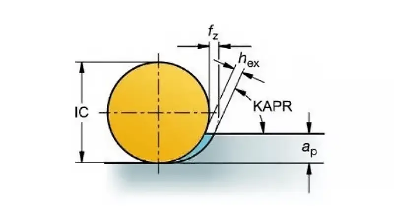
- The recommended value of hex is 0.10-0.20 mm (0.0039-0.0079 inch). Low values may cause burr formation.
- Due to the high table feed, a machine tool with “pre-reading” function should be used to avoid dimensional errors.
- The tool’s lifespan is always limited by burr formation or the surface quality of parts. Blade wearing is difficult to use as a tool life criterion.
05 Superalloy and titanium alloys
The milling of superalloys and titanium typically necessitates a machine tool with high rigidity, power, and torque, which can operate at low speeds.
The two most common types of wear are notch wear and cutting edge tipping.
The excessive heat generated during the milling process can constrain the cutting speed.
One possible suggestion is to maximize the use of round blade milling cutters, which can enhance the chip thinning effect.
The use of round blade milling cutters minimizes notch wear
When the cutting depth is less than 5mm, the entry angle should be below 45°.
In practical applications, it is recommended to use a positively-rounded blade.
To maintain a constant load per tooth and ensure a smooth process, as well as prevent premature failure of individual inserts, both radial and axial accuracy of the cutter are necessary.
The cutting edge should always be grooved at a positive rake angle and optimally rounded to prevent chips from adhering to it when the tool is retired.
During milling, it is best to engage as many cutting teeth as possible.
Under stable conditions, this will achieve ideal productivity.
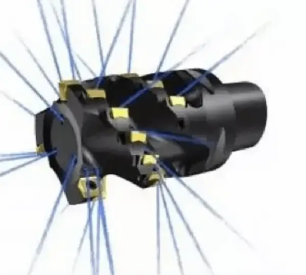
To use a superdensity tooth milling cutter.

Yellow: Tool lifespan; Black: Tool lifespan decreases as cutting parameters increase
The tool life is affected differently by various changes, with cutting speed (Vc) having the greatest impact, followed by ae, and so on.
Cutting fluid/coolant
When it comes to milling, unlike other materials, it’s always advisable to use coolant to aid chip evacuation and regulate the heat at the cutting edge while preventing secondary chip cutting.
Internally cooled high-pressure coolant (70 bar) delivered via the spindle/tool is generally preferred over low-pressure externally cooled coolant.
However, it’s important to note that there is an exception to this rule. When milling with ceramic inserts, cutting fluid should be avoided due to the risk of thermal shock.
When using cemented carbide blades, internal cooling will bring benefits
Blade/tool wear
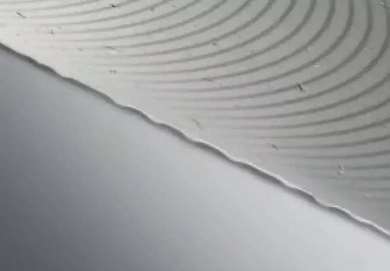
The most common causes of tool breakage and poor surface quality are groove wear, excessive flank wear, and chipped edge lines.
To ensure a reliable machining process, the best solution is to frequently index the cutting edge. The flank wear of the cutting edge should not exceed 0.2mm for milling cutters with an entering angle of 90°, or the maximum should not exceed 0.3mm for round inserts.
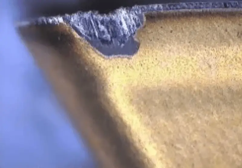
Typical blade wear
Be applied in ceramic blade milling cutter for rough machining of superalloy.
Ceramic milling has a faster speed than cemented carbide milling, typically 20-30 times faster, despite a lower feed rate (around 0.1mm/z). This results in a significant boost in productivity.
The milling process uses interrupted cutting, resulting in much lower temperatures than turning.
Therefore, a cutting speed of 700-1000m/min is recommended for milling, compared to only 200-300m/min for turning.
Here are some suggestions:
(1) To ensure a small entering angle and prevent notch wear, use round blades.
(2) Avoid using cutting fluid/coolant.
(3) Do not use ceramic blades when processing titanium alloys.
(4) Ceramics can negatively affect surface integrity and other indicators. Hence, avoid using ceramic blades when the finished part’s shape is ready for processing.
(5) The maximum flank wear allowed when machining high-temperature alloys with ceramic inserts is 0.6mm.
06 Hardened steel milling
This group of materials includes tempered steel with a hardness greater than 45-65HRC. Typical milling parts include stamping molds, plastic molds, forging molds, and die-casting dies. Blade debris/flank wear and workpiece tipping are the main issues.
Here are some suggestions:
(1) Use a positive rake insert geometry with sharp cutting edges. This reduces the cutting force and creates a smoother cutting action.
(2) Dry cutting without cutting fluid is recommended.
(3) Cycloid milling is an appropriate method that achieves high table feed and low cutting force simultaneously. This keeps the cutting edge and workpiece at a low temperature, improving productivity, tool lifespan, and part tolerances.
(4) In face milling, use a light cutting strategy with small depths of cut (ae and ap). Use an ultra-close pitch milling cutter and a relatively high cutting speed.