What is Hydraulic Press Machine?
Hydraulic Press Definition
The hydraulic press is a type of machine that utilizes liquid as a working medium to transfer energy, based on Pascal’s principle, to accomplish various tasks.
Typically, a hydraulic press machine is composed of three components: the mainframe, the power system, and the hydraulic control system.
Further reading:
Brief Introduction of Hydraulic Press
The hydraulic press machine (also referred to as a hydraulic oil press) utilizes the static pressure of a liquid to process materials such as metal, plastic, rubber, wood, and powdered products.
It is commonly utilized in pressing and forming processes, including forging, stamping, cold extrusion, straightening, bending, flanging, sheet drawing, powder metallurgy, and pressing.
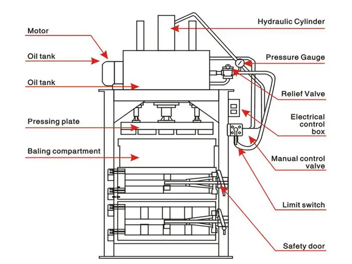
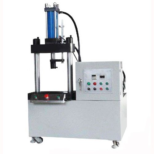
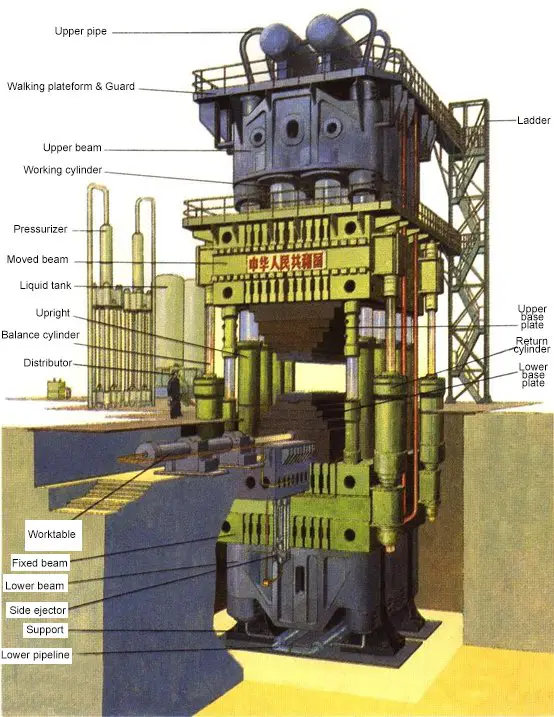
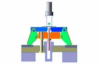
Fig.2 Hydraulic Press Machine Structure
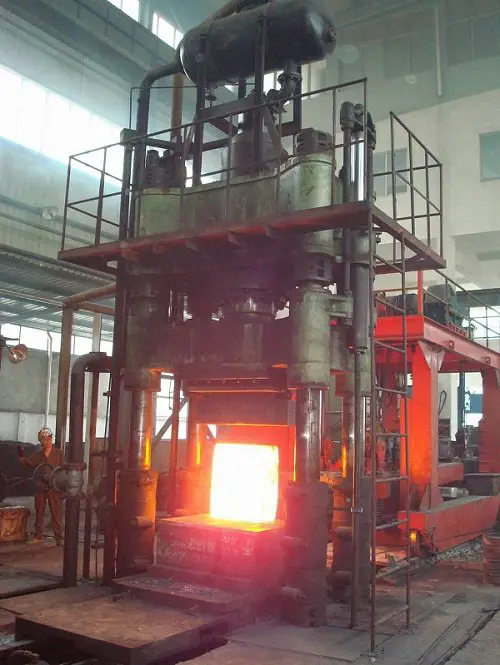
Biggest Hydraulic Press
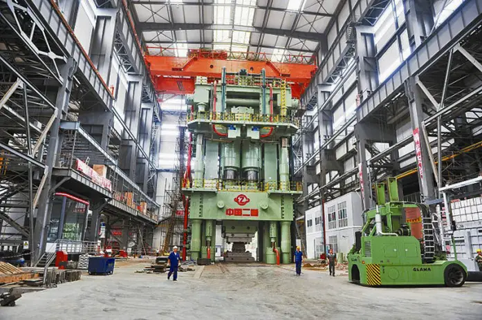
Fig.3 80,000 Ton Die Forging Press
The 80,000-ton die-forging hydraulic press stands 27 meters tall on the ground and 15 meters underground, making it a total height of 42 meters and a total weight of 22,000 tons, thereby earning its title as the world’s most powerful and strongest hydraulic press.
As a national treasure-class strategic equipment, the giant die-forging hydraulic press represents the strength of the heavy industry. Only a few countries in the world possess the capability to manufacture such a hydraulic forging press.
Presently, only China, the United States, Russia, and France possess die-forging presses with a capacity of over 40,000 tons.
The United States constructed two of the largest 45,000-ton die-forging presses in the world in 1955, and they are still in operation today. In 2001, another 40,000-ton die-forging press was erected at the Shultz Steel Mill in California.
The Soviet Union built two massive 75,000-ton die-forging presses in 1961. France acquired a 65,000-ton die-forging press from the Soviet Union in 1976 and developed a 40,000-ton die-forging press in collaboration with Germany in 2005.
China’s first 30,000-ton die-forging press remained inactive for almost 40 years after it was built in 1973. However, in the last two years, several massive presses have been developed rapidly, with 30,000-ton, 40,000-ton, and 80,000-ton die-forging presses being built in 2012 alone.
The 80,000-ton hydraulic press broke the world record previously held by the Soviet Union for 51 years.
The die-forging press is primarily used to produce high-strength titanium/aluminum alloy forgings for industries such as aerospace, nuclear power, and petrochemicals.
Any country possessing a large die-forging press is considered to have a formidable aviation industry globally.
History of Hydraulic Press Machine
In 1795, British engineer J. Brammer utilized PASCAL’s principle to invent a water press for pressing and packaging vegetable oils.
By the mid-19th century, Britain had begun to use hydraulic presses for forging, gradually replacing the massive steam hammers.
By the end of the 19th century, the United States had constructed 126,000-ton free-forging hydraulic presses.
Since then, the world has produced over 20 sets of 10,000-ton free-forging hydraulic machines, including two manufactured in China (as shown in Figure 4).
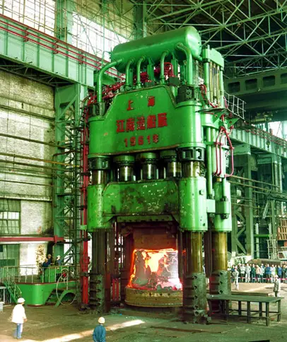
Fig.4 Free-forging hydraulic machines
With the advancement and enhancement of the electric high-pressure pump, the forging hydraulic press has been evolving towards smaller tonnages.
In the 1950s, small and fast forging hydraulic presses emerged, capable of performing tasks equivalent to those of a 3-5 ton forging hammer.
In the 1940s, Germany produced a massive 18,000-ton die-forging press. Since then, the world has created 18 sets of 18,000-ton forging hydraulic machines, with one made in China being 30,000-ton.
Types of Hydraulic Press Machine
According to the structural form, the hydraulic press machine is mainly divided into:
- Four-column hydraulic press
- Single column hydraulic press (C type)
- Horizontal hydraulic press
- Vertical frame hydraulic press
- Universal hydraulic press
If classified by tonnage, the hydraulic press can be divided into:
- 63T hydraulic press machine
- 100T hydraulic press machine
- 150T hydraulic press machine
- 200T hydraulic press machine
- 250T hydraulic press machine
- 300T hydraulic press machine
- 315T hydraulic press machine
- 500T hydraulic press machine
- 630T hydraulic press machine
- 800T hydraulic press machine
According to the applications, it is mainly divided into metal forming, bending, stretching, punching, powder (metal, non-metal) forming, pressing, extrusion and so on.
Hot forging hydraulic press
As one of the most frequently used equipment in the forging industry, the large hydraulic forging machine is capable of performing various free forging techniques.
Currently, there are several series of forging hydraulic presses with specifications of 800, 1600, 2000, 2500, 3150, 4000, and 5000 tons.
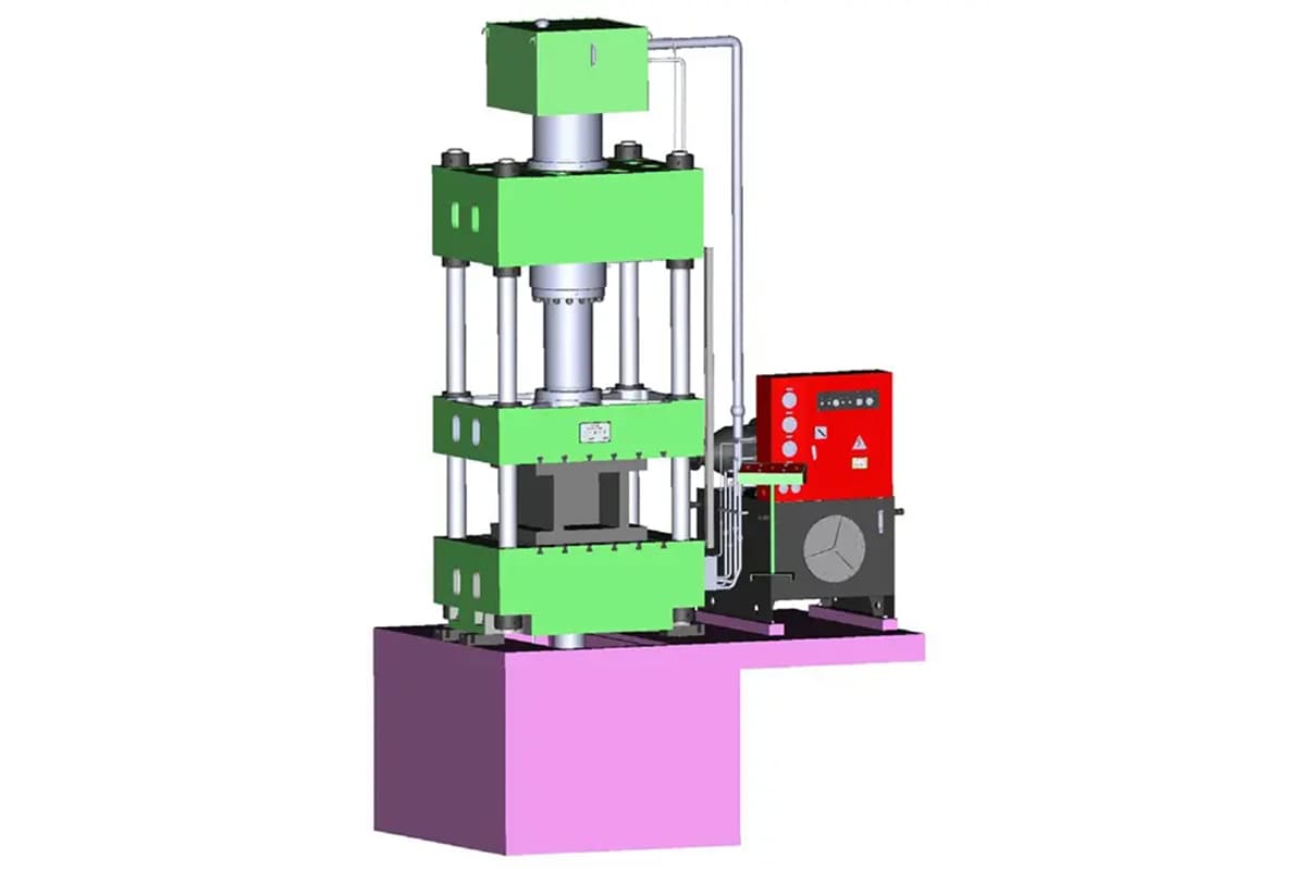
Four-column hydraulic press
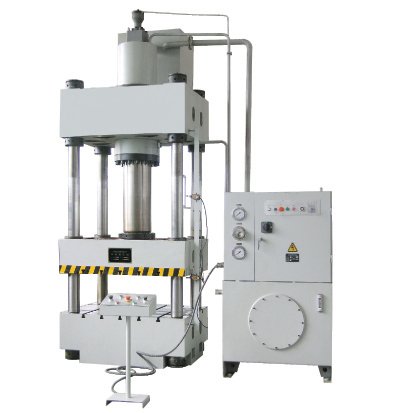
The four-post hydraulic press is ideal for pressing plastic materials, such as powder product forming, plastic product forming, cold (hot) extrusion metal forming, sheet drawing, transverse pressing, bending, stamping, and correction processes.
The four-post hydraulic press can be further divided into four-post two-beam hydraulic press, four-post three-beam hydraulic press, and four-post four-beam hydraulic press.
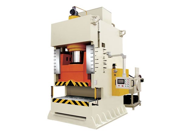
C-frame hydraulic press
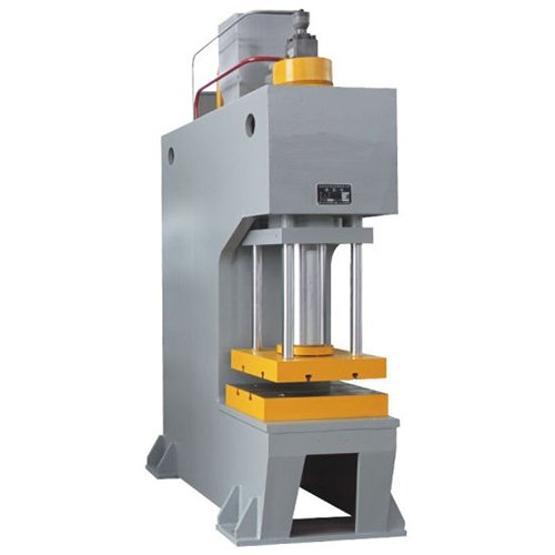
The working range of the hydraulic press can be extended by using a three-sided space with maximum retractability of 260mm-800mm.
It also has the ability to preset the working pressure and is equipped with a heat abstraction device.
Horizontal hydraulic press
The machine parts can be assembled, disassembled, straightened, compressed, stretched, bent, punched, and more, making it a versatile machine.
The working table of the machine is designed to move up and down, expanding the opening and closing height of the machine for added convenience in use.
Two-pillar hydraulic press
This series of products is suitable for pressing, bending, and shaping all types of parts, including stamping indentations, flanging, punching, and light stretching of small parts. It is also suitable for forming metal powder products.
With electric control, it has job motion and semi-automatic cycle capabilities, which can protect against pressure delay time.
It also has a good sliding block direction, is easy to operate and maintain, and has economic durability.
Users can add thermal instruments, an ejector cylinder, a travel display, and counting functions as needed. The two-pillar hydraulic press is based on Pascal’s law and utilizes fluid pressure transmission.
There are many types of two-pillar hydraulic presses, which can be divided into oil presses and water presses based on the type of liquid that transfers pressure.
Water presses produce a large total pressure and are often used for forging and stamping.
Forging presses are further divided into die forging water presses and free forging water presses. Die forging water presses require the use of a mold, while free forging water presses do not.
Working Principle of Hydraulic Press Machine
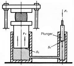
Fig.5 Hydraulic press mechanism
The area of the large and small plungers are S2 and S1, respectively, and the forces on them are F2 and F1, respectively.
According to Pascal’s principle, the pressure of the confined liquid is equal everywhere, meaning F2/S2 = F1/S1 = p; F2 = F1(S2/S1).
The gain effect of hydraulic pressure is the same as mechanical gain, meaning the force is increased but the work is not gained. As a result, the motion distance of the large plunger is S1/S2 times that of the small plunger.
The basic principle of the hydraulic press is that an oil pump transfers hydraulic oil to integrated cartridge valve blocks, which are then directed to the upper or lower chamber of the cylinder through a one-way valve and a relief valve.
Under the action of high-pressure oil, the oil cylinder begins to move up and down.
The hydraulic press is a device that makes use of liquid to transfer pressure, utilizing Pascal’s law in the transfer of pressure within a closed container.
The four-column hydraulic press’s hydraulic drive system consists of power mechanism, control mechanism, executive mechanism, auxiliary mechanism, and working medium.
Typically, an oil pump is used as the power mechanism, with one or more pumps selected to meet the requirement of the actuator’s running speed.
- Gear pump for low pressure (oil pressure less than 2.5mp);
- Blade pump for medium pressure (oil pressure less than 6.3mp);
- Plunger pump for high pressure (oil pressure less than 32.0MP).
Working Medium
The function of the working medium used in a hydraulic press is not only to transfer pressure, but also to ensure that the components of the hydraulic press machine are sensitive, reliable, long-lasting, and have minimal leakage.
The basic requirements for a working medium in a hydraulic press are:
- Good fluidity and low compressibility to improve transmission efficiency.
- Anti-rust properties.
- Good lubrication performance.
- Easy to seal.
- Stable performance and long-term stability without deterioration.
Historically, water was used as the working medium in hydraulic presses.
Later, emulsified liquid was introduced by adding a small amount of oil to the water to improve lubrication and reduce corrosion.
Mineral oil was later introduced as the working medium in hydraulic presses in the late 19th century. The oil had good lubricity, anti-corrosive properties, and moderate viscosity, which improved the performance of hydraulic presses.
In the second half of the 20th century, a new type of water-based emulsifying solution was developed, characterized as “oil-in-water” rather than “water-in-oil.”
This solution had properties similar to oil, including good lubrication and anti-corrosion properties, but with the added benefit of containing little oil and being less flammable.
However, the higher cost of water-based emulsions has limited their widespread use.
Parts And Functions of Hydraulic Press Machine (Structure)
Drive System
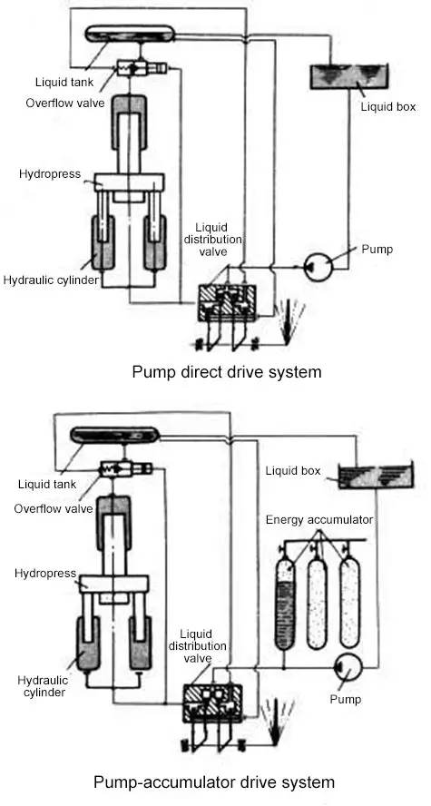
Fig.6 Hydraulic press machine drive system
The driving system of hydraulic press mainly consists of two types: pump direct drive and pump-accumulator drive.
Pump Direct Drive:
In this system, the pump provides high-pressure working fluid to the hydraulic cylinder, and a distribution valve is used to change the direction of the supply liquid.
The overflow valve is used to adjust the limited pressure of the system and acts as a safety overflow.
This drive system is simple in structure, has fewer processes, and the pressure can automatically increase and decrease according to the work required force, which reduces power consumption.
However, the capacity of the pump and drive motor must be determined based on the largest required force and maximum working speed of the hydraulic press.
This type of drive system is mainly used for medium and small-sized hydraulic presses and can also be used for large (such as 12000T) free forging hydraulic presses that are directly driven by the pump.
Pump-Accumulator Drive:
This system has one or a set of accumulators, and when the high-pressure working fluid supplied by the pump is in surplus, it is stored by the accumulator.
When the supply is insufficient to meet the demand, it is supplied by the accumulator.
The capacity of the pump and motor can be selected based on the average amount of high-pressure working fluid required if this system is adopted.
However, the energy consumption is high, the system has many processes, and the structure is complex due to the constant working fluid pressure.
This type of drive system is used for large hydraulic presses or a set of the drive system to drive several hydraulic presses.
Structure
According to the direction of force, hydraulic presses are classified into vertical and horizontal types. The majority of hydraulic presses are vertical, while those used for extrusion are horizontal.
In terms of structure type, hydraulic presses can be two-column, four-column, eight-column, welding frame, and multi-layer steel strip winding frame types. Medium and small vertical hydraulic presses usually have a C-frame type.
The C-frame hydraulic press is open on three sides and is easy to operate, but it has a lower degree of rigidity.
The welding frame hydraulic press, used for stamping, is rigid and open at the front and back, but closed on the left and right.
In a vertical transmission four-column free forging hydraulic press, the oil cylinder is fixed on the upper beam, and the plunger is firmly attached to the movable beam.
The movable beam moves up and down under the pressure of the working fluid, guided by the vertical column.
The movable beam has workbenches that move back and forth, with an upper anvil and lower anvil installed respectively under the movable beam and on the worktable.
The working force is supported by a frame composed of upper and lower beams and columns.
Large and medium-sized free forging hydraulic presses, which are typically driven by a pump-accumulator system, usually adopt three working cylinders to achieve three-level working forces.
There are also balancing cylinders and return cylinders outside the working cylinders that apply upward force.
Advantages of Hydraulic Press Machine
Compared to traditional stamping methods, hydroforming boasts clear technical and economic benefits such as weight reduction, decreased number of parts and molds, improved rigidity and strength, and reduced production costs.
This technology is seeing increasing use in various industries, particularly in the automotive sector.
The goal of reducing structural weight and energy consumption during operation is a long-term objective in industries such as automobiles, aviation, and aerospace.
Hydroforming is an advanced manufacturing technology that helps achieve this goal and is a trend in the development of advanced manufacturing.
In comparison to stamping and welding technologies, hydroforming has several key advantages:
Decreased weight and material savings:
For parts such as engine brackets and radiator brackets, hydroformed parts can be 20-40% lighter than stamped parts. For hollow step shaft parts, weight reduction can reach 40-50%.
Reduced number of parts and molds and lower mold costs:
Hydroformed parts typically only require one set of molds, whereas many stamped parts require multiple sets.
Hydroforming has reduced the number of engine bracket parts from 6 to 1 and radiator bracket parts from 17 to 10.
Lower subsequent machining and assembly welding:
For example, the radiator support has seen a 43% increase in heat dissipation area, a decrease in soldering points from 174 to 20, a decrease in processes from 13 to 6, and a 66% increase in productivity.
Improved strength and rigidity, especially fatigue strength:
For instance, the rigidity of a hydroformed radiator bracket can increase by 39% in the vertical direction and 50% in the horizontal direction.
Lower production costs:
Statistical analysis of hydroformed parts has shown that the average production cost is 15-20% lower than that of stamped parts, and mold costs are 20-30% lower.”
Application of Hydraulic Press
Hydraulic presses can be utilized for various metal sheet forming processes such as drawing, turning, bending, and stamping. It can also be adapted for general pressing needs with the addition of blanking buffer, blanking, and moving table devices, as per the user’s requirements.
In addition to forging and forming, the three-beam four-column hydraulic press can also be utilized for correction, press fitting, packaging, briquetting, and plate pressing.
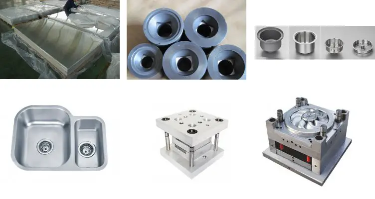
Materials suitable for the hydraulic forming process include carbon steel, stainless steel, aluminum alloy, copper alloy, and nickel alloy.
In general, any material suitable for cold forming can be used in the hydraulic forming process.
Hydraulic forming technology is widely used in various industries, including automobile factories, electronics factories, electric appliance factories, heat treatment plants, gear factories, and air conditioning parts factories.
Additionally, hydraulic forming is widely used in the automobile, aviation, aerospace, and pipeline industries. It is mainly applicable to:
- Hollow structural parts with circular, rectangular or special-shaped sections changing along the axis of the components, such as the special-shaped pipe parts of the exhaust system of an automobile;
- Non-circular hollow frame, such as engine bracket, instrument panel bracket and body frame (accounting for 11% ~ 15% of vehicle quality);
- Hollow shaft parts and complex pipe fittings etc.
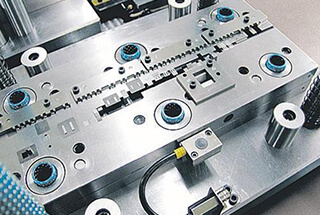
Accessories for Hydraulic Press Machine
| 1 | The gear pump |
| 2 | Hydraulic overflow valve |
| 3 | Miniature contactor |
| 4 | Proximity switch |
| 5 | O-ring |
| 6 | U-ring |
| 7 | Anti-dust ring |
| 8 | Guide ring |
| 9 | Ladder ring |
| 10 | Hole use YX ring |
| 11 | Combined seal ring |
| 12 | The gear pump |
How to Build A Hydraulic Press Machine
DIY 5 ton hydraulic press
Hydraulic Press Machine Operation
Different types of hydraulic press machines operate differently, and every hydraulic press manufacturer will provide an operation manual along with the machine upon delivery.
This manual serves as the best training material for learning the key points of how to use the hydraulic press.
As a user of a four-pillar hydraulic press machine, you can also refer to our hydraulic press user manual for further information.
Hydraulic Press Machine Commissioning
- Turn the working mode switch to the “inching move” position and loosen the adjusting handle of the pressure control valves on the power station.
- Switch on the power and jog the motor to check its rotation, ensuring that it is consistent with the specified rotation. After completing this check, the motor can be officially started, and the oil pump can operate at an empty load for at least 5 minutes. Then, inspect all parts to ensure that there are no abnormalities. If everything is normal, the system pressure can be raised to around 6 Mpa in preparation for the next task.
- Press the “press” button to cause the piston of the main cylinder to descend. The piston head should touch the upper plane of the slider. Then install the large flange, making sure that the distance between the flange end face and the upper plane of the slider is 5mm. When the pressure rises to the preset 6 Mpa and stops, tighten the connecting bolt using a wrench while still under pressure.
- Press the “return” button to raise the slider to the upper dead center, and place the test anvil (metal pad) in the center of the worktable. The height of the testing anvil should not be less than 500mm, its length and width should not be less than 600mm, the parallelism of its upper and lower surfaces should be less than 0.02/500mm, and it should have sufficient strength to bear the full load.
- Adjust according to the accuracy standard specified in the certificate of conformity. Typically, the parallelism between the lower plane of the slider and the working table is adjusted first by adjusting the four adjusting nuts under the upper beam after adding pressure. Once passed, tighten the four lock nuts above.
- When the pilot valve “F2” is adjusted to stop the slider at any position during the test run, as described above, there should be no sliding. However, it should be noted that the pressure value should provide enough return force. When descending slowly, adjust the pilot valve “F3” to the upper cavity of the main cylinder, and the pressure value should be less than 1 Mpa.
- The pressure range is typically 5 Mpa to 25 Mpa, or 60T to 315T. When adjusting the electric contact pressure gauge “F12”, the pilot valve “F1” should also be adjusted accordingly. Generally, the system pressure should be about 1 Mpa higher than the predetermined pressure of the contact pressure gauge “F12”. If the pressure is less than 5 Mpa, the table “F12” may have an upthrust.
- When drawing, the adjustment of the pressure side force is done with the pilot valve “F7”, which should be fixed at 25 Mpa. The adjustment of the system pressure is done with the pilot valve “F1”, which is usually fixed at 25 Mpa.
- Measure the speed of each action stroke as required, and ensure that the movement of each unit of the travel limiter is reliable.
- After testing the pressure protection performance, stop the vehicle under pressure, and the pressure drop within 10 minutes should be no more than 2 Mpa.
- Measure the machine accuracy again.
Note: Each hydraulic press machine operates differently, and the manufacturer will provide an operation manual with the machine. This manual will be the best training material for learning how to use the machine.
At this point, the whole commissioning of hydraulic press machine is finished and can be put into production.
Hydraulic Press Machine Maintenance
The recommended oil for hydraulic press machines is #32 and #46 anti-wear hydraulic oil, with a temperature range of 15 to 60°C.
Before adding to the tank, the oil must be strictly filtered.
The working oil should be changed once a year, with the first change not exceeding three months.
The sliding block should be lubricated frequently, and the appearance of the vertical column should be kept clean. Machine oil should be added before each work.
Under a nominal pressure of 500T, the maximum allowed eccentricity of the central load is 40mm. Excessive eccentricity can easily cause post-tension or other adverse effects.
Pressure gauges should be calibrated and inspected every six months.
When the machine is not in use for a long period, each part’s surface should be cleaned and coated with anti-rust oil.
First class maintenance
The primary maintenance for the hydraulic press machine is to be conducted after it has run for 500 hours, with the responsibility primarily falling on the operators and with support from maintenance workers.
To begin maintenance, make sure first to turn off the power supply, then proceed according to the maintenance schedule outlined in the table below.
| No. | Position | Maintenance details and requirements |
| 1 | External maintenance | 1. Clean the outside surface of hydraulic press, maintain inside and outside clean, no rust. |
| 2. Complete the missing screws, nuts, buttons, signs, etc. | ||
| 2 | Beam, column guide | 1. Clean the outer surface of upper and lower beams and movable beams, as well as pillar, guide rail, slide block and press plate. Clean without oil, yellow robe and rust stain. |
| 2. Remove the burrs on the bottom surface of the movable beam and the upper surface of the lower beam as well as on the pillar, guide rail and slider. | ||
| 3. Check and tighten the fasteners of the beam and column guide rails. | ||
| 3 | Hydraulic, lubrication | 1. Wipe and check the surface of oil pump, valve, oil tank and pipeline, clean, rust free, oil free, no yellow robe, no leakage. |
| 2. Clean the oil cup, filter screen, dredge the oil road, the oil mark is clear. | ||
| 3. Check the oil quality and quantity in the fuel tank, add lubricating oil as appropriate. | ||
| 4. Check gauge | ||
| 5. Check the lubrication of columns and guide rails. | ||
| 4 | Electric | 1. Clean the electrical box without dirt or grease. |
| 2. Check the integrity of the line, hose protection connection reliable, good performance. | ||
| 3. Check the travel switch of movable beam, check whether the action is sensitive and reliable. | ||
| 4. Safety protective cover, pillar protective cover complete and easy to use, foot pedal switch protective cover intact, safe and reliable. | ||
| 5. Check and tighten the zero connecting device. |
Second-class maintenance
| No. | Position | Maintenance details and requirements |
| 1 | Beam, column guide | 1. Check and adjust the horizontal plane of the beam, guide rail, guide sleeve, slide block and press plate of the column so as to achieve smooth movement and meet the technical requirements. |
| 2. Repair or replace defective parts. | ||
| 2 | Hydraulic, lubrication | 1. Disassemble and repair solenoid valve, grinding valve and valve core. |
| 2. Clean and inspect oil pump, cylinder and plunger, repair burrs and replace oil seal. | ||
| 3. Check pressure gauges. | ||
| 4. Repair or replace badly worn parts. | ||
| 5. Start the hydraulic press machine to check whether the movement of each cylinder and plunger is smooth, no crawling. Check whether the support valve can stop the moving beam in any position accurately and the pressure drop meets the process requirements. | ||
| 3 | Electric | 1. Clean motor, check bearing and replace grease. |
| 2. Repair or replace damaged components. | ||
| 3. The electrical appliances meet the requirements of the equipment standard. | ||
| 4 | Accuracy | 1. Calibrate machine tool level, check, adjust and repair accuracy. |
| 2. Accuracy in accordance with the equipment integrity standards. |
Hydraulic Press Machine Troubleshooting
You can check out the common faults and troubleshooting solutions for hydraulic press machine in our previous written article.
Hydraulic Press Safety Rules
Safety regulations
Individuals who are not familiar with the structure and performance of the hydraulic press machine or its operating procedures should not operate the machine without obtaining proper authorization.
The machine must not be overhauled or tampered with while it is in operation.
In case of serious oil leakage or other abnormal conditions (such as unreliable operation, loud noise, or vibration), the operator must immediately stop the machine and investigate the cause in order to resolve the issue.
The machine should not be used if an overload occurs or if the maximum eccentricity is exceeded.
Exceeding the maximum stroke of the slider is strictly prohibited. The minimum closing height of the mold must not be less than 600mm.
The electrical equipment must have a secure and reliable grounding system.
At the end of each work day, the slider should be moved to its lowest position.
Hydraulic Press Tonnage Calculations
The hydraulic press is becoming increasingly popular in industrial production due to advancements in industry and hydraulic technology.
Regardless of whether you are a manufacturer or user of a hydraulic press, it is crucial to understand how to calculate hydraulic press tonnage.
As a professional manufacturer, we will provide you with information on the amount of force exerted by a hydraulic press and the significance of this information.
In order to determine the tonnage of the hydraulic cylinder, it is necessary to know the working pressure of the hydraulic system and the inner diameter and outer diameter of the cylinder rod (which will be required when calculating the tensile force of the hydraulic cylinder).
The equation for hydraulic press tonnage calculation formula:
Pushing force of hydraulic cylinder = Hydraulic cylinder inner section area (or the piston sectional area) × working pressure
Hydraulic cylinder inner section area = π*D2/4 = 3.14 × D2 ÷ 4
Working pressure: equals to the pressure shown on the pressure gauge during the maximum load operation
For example:
Assuming the hydraulic cylinder has an inner diameter of 10cm and a working pressure of 16MPa (160kgf).
The inner section area of the hydraulic cylinder can be calculated as follows: 3.14×10×10÷4=78.5cm2
Therefore, the pushing force can be calculated as follows: 78.5 x 160 = 12560kg = 12.56 tons.
To make it easier, we have created a hydraulic press tonnage calculator.
By using this formula, we can quickly determine the tonnage of the hydraulic press that we have purchased or are looking to purchase, and avoid paying a high price for equipment with a low tonnage.
Additionally, we can calculate the working pressure of our own hydraulic press with this formula in order to prevent overloading the equipment and improve its longevity and performance.
Buying Guide for Hydraulic Press Machine
Before purchasing a hydraulic press machine, you may be wondering what size is best suited for your needs. This issue can easily be resolved by using the hydraulic press tonnage calculation formula outlined above.
However, you may find yourself unsure of where to buy the hydraulic press. There are many factors that could influence your decision, and there are many reputable hydraulic press machine manufacturers around the world.
Despite this, the most cost-effective hydraulic press machines are often produced by manufacturers in China.
It is important to take the time to find a reliable and trustworthy hydraulic press manufacturer, which will provide you with all the necessary specifications and cost information for the hydraulic press you require.
Further reading:
Hydraulic Press Crushing Things
Many people are curious about the items that can be crushed by a hydraulic press and those that can resist it.
The answer to this question should depend on the tonnage of the hydraulic press in question.
If you have access to a hydraulic press in your workshop, you can conduct a test to find out the results.
Maybe in the future, we’ll have the opportunity to try this experiment as well.
Hydraulic Press Terminology
Here is a list of 7 commonly used terms for hydraulic press operation. Experienced engineers and operators should be familiar with all of them, but newcomers may not be. Let’s take a closer look.
Nominal Pressure: The highest pressure that a machine can be used at continuously.
Motive Seal: The sealing of the sliding parts in a hydraulic press, which is known as the motive seal.
Circuit Diagram: A representation of the hydraulic system using professional graphic symbols.
Hydraulic Drive System: A device that converts fluid pressure into power, known as the hydraulic transmission device.
Hydraulic Pressure Station: A hydraulic device made up of components such as a fuel tank, hydraulic pump, motor, control valve, etc.
Hydraulic Balance: The weight supported by balancing the fluid pressure, including the hydraulic press equipment itself.
Oil Drainage: The return of oil from a pipe in a hydraulic device to a tank or collector is referred to as oil drainage.
Difference Between Mechanical Press and Hydraulic Press
Hydraulic press drawing refers to the process of positioning the blanking part in the mold during the hydraulic press drawing. The blanking ring controls the flow of metal to form a hollow workpiece.
In general, deep drawing refers to a workpiece whose depth is greater than 1/2 of its diameter.
The blanking process in a punching machine involves cutting and punching the plate to form the desired shape. The material used can be a single sheet or a continuous strip.
Stamping encompasses not only blanking but also forming, bending, flanging, and hole punching processes.
If the drawing process is added to the blanking process on a punch machine, the press can be referred to as a hydraulic punch press.
In general, punching machines have a simple structure, fast production speed, and high efficiency, making them suitable for high-volume and simple blanking forming.
On the other hand, hydraulic presses are better suited for the production of medium to small batches with a need for accuracy, depth, and a changeable shape.
These presses have precise requirements for the slider velocity, pressure, and position, and can be custom-made to meet specific orders.
When customers are looking to purchase processing machinery, they should choose the appropriate hydraulic or mechanical press based on their actual processing needs.
Hydraulic Press V.S Hydraulic Jack
5 Ton Hydraulic Jack vs 500 Ton Hydraulic Press
Conslusion
After reading the above information, you should now have a comprehensive understanding of hydraulic presses.
If you are in the market to buy a hydraulic press for your workshop, this article on purchasing one may be of help to you.
Additionally, you can reach out to us to get a quote for a hydraulic press.
We are about to purchase a hydraulic press for our production how can I identify which tonnage is suitable for my work. please suggest.
In this post we have taught you how to calculate the required tonnage of the hydraulic press, pls read it again.
Which press construction method is preferred in case of significant off-center loads?
What is normal off-center load design limit for most press suppliers? (Nm)
hello, do you export to Argentina?
Yes
what is the running time of press per a day
That depends.
What kind of material are used on the columns on a large press 1060? where can you buy it in USA
Hi, I am a student. First of all, thank you very much for the useful information you provided. I am trying to use parts of this information in a research but it seems that the website does not allow copying of the content. Do I need a license or premission and how can i get it??
Sorry, our site doesn’t support copy now.
How much pressure is suitable for concrete cover block making machine
Hi, could you help me ? What is the service life of a hydraulic plate vulcanizing system with plate dimensions of 2700 x10,000 with 12 cylinders? Can you recommend articles to me? or sites that talk about the useful life of machines like this? hydraulic units and etc. ? :) Do you know something about this too ? :)