Pneumatic Transmission
Pneumatic transmission involves the transfer of power by gas pressure or fluid by compressed gas as the working medium.
The power transfer system involves compressed gas being transferred through pipes and control valves to the pneumatic actuator, which transforms the pressure of the compressed gas into mechanical energy.
The information transmission system involves the use of pneumatic logic elements or jet elements to perform logic operations, also known as a pneumatic control system.
Characteristics of pneumatic transmission
With a low working pressure averaging 0.3 to 0.8 MPa, pneumatic systems have low gas viscosity and experience minimal loss in pipelines, making them advantageous for gas supply and transportation over moderate distances. These systems are also safe to use, as there are no explosion or shock hazards, and have overload protection capabilities. However, it should be noted that pneumatic systems require a supply of compressed air.
Composition of pneumatic transmission
Pneumatic transmission comprises an air source, pneumatic actuator, pneumatic control valve, and pneumatic accessories.
Air sources are typically supplied by compressors.
The pneumatic actuator converts the pressure of the compressed gas into mechanical energy to drive working parts, such as cylinders and pneumatic motors.
The pneumatic control valve adjusts the direction, pressure, and flow of the air and is categorized into directional control valves, pressure control valves, and flow control valves.
Pneumatic accessories include air purifiers, air lubricators, noise mufflers, and pipe joints, among others.
Aerodynamic sensors are also utilized to sense and transmit information in pneumatic transmission systems.
Advantages of pneumatic transmission
Pneumatic transmission uses air as a medium, which is an inexhaustible and easily accessible source that can be directly discharged after use without polluting the environment. Furthermore, the pipeline is not complex as there is no need for a return pipe.
Air has low viscosity and flow energy dissipation, making it suitable for centralized gas supply and long-distance transportation.
Pneumatic transmission is safe and reliable, requiring no fire or explosion protection, and can operate in environments with high temperatures, radiation, humidity, dust, and other conditions.
Pneumatic transmission is quick, and the structure of pneumatic components is simple, making them easy to process and maintain with a long service life. The pipeline is not prone to clogging, and the medium does not have problems with metamorphic replacement.
Disadvantages of pneumatic transmission
The large compressibility of air can negatively impact the dynamic stability of pneumatic systems, resulting in a significant impact on working speed due to load changes.
The low pressure of pneumatic systems makes it difficult to produce large output and torque.
Air control signal transmission is slower than that of electronic and light-speed systems, making it unsuitable for high-speed and complex transmission systems.
Pneumatic systems generate large exhaust noise.
Hydraulic Transmission
Hydraulic transmission is the transmission of energy and control by using the liquid as the working medium.
The basic principle of hydraulic transmission
Hydraulic pumps convert mechanical energy into liquid pressure energy, which is then transferred via changes in liquid pressure. A variety of control valves and pipes are used to transmit energy to hydraulic actuators, such as hydraulic cylinders or motors, which convert liquid pressure into mechanical energy to drive the work mechanism, enabling straight-line reciprocating and rotary motion.
The liquid used is called the working medium, and mineral oil is commonly used for this purpose.
The function of hydraulic transmission is similar to that of transmission elements in mechanical transmission, such as belts, chains, and gears.
Hydraulic transmission system
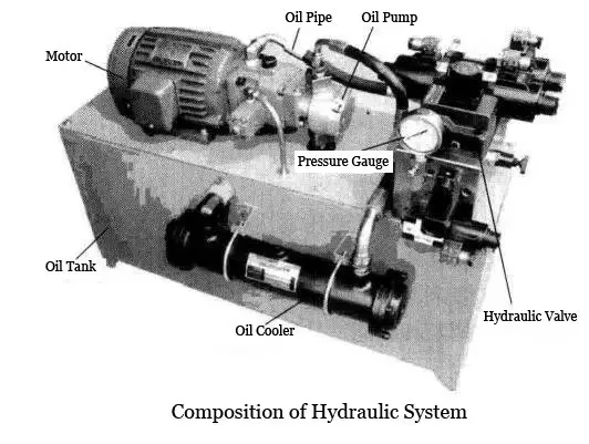
The hydraulic system comprises a hydraulic pump, hydraulic control valve, hydraulic actuators (such as hydraulic cylinders and motors), and hydraulic auxiliary parts (including pipelines and accumulators, among others).
Press brake machines are an example of a system that utilizes hydraulic transmission.
Components of the hydraulic transmission system
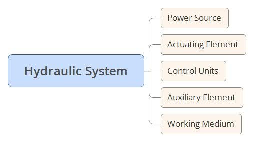
The hydraulic system comprises several components, including power components (such as the hydraulic pump), actuators (including hydraulic cylinders and hydraulic motors), control elements, auxiliary components (such as fuel tanks, oil filters, pipes and joints, coolers, pressure gauges), and the working medium (i.e., hydraulic oil).
Power components, such as the hydraulic pump, convert mechanical energy into fluid kinetic energy (pressure and flow) and provide pressure oil to the hydraulic system, acting as the system’s power source.
Actuators, such as hydraulic cylinders or hydraulic motors, convert hydraulic energy to mechanical energy and are isothermal. Hydraulic cylinders drive mechanisms to perform linear reciprocating or movement, while hydraulic motors perform turning motion.
Control elements, which refer to various components, are used to control and adjust fluid pressure, flow, and direction in the hydraulic system, ensuring that the actuators work according to the required specifications.
Auxiliary components provide the necessary conditions for the system to operate correctly, and they facilitate monitoring and control.
The working medium is the transmission fluid, typically hydraulic oil. The hydraulic system utilizes this working medium, which also lubricates the moving parts of the hydraulic components.
The working principle of the hydraulic transmission system
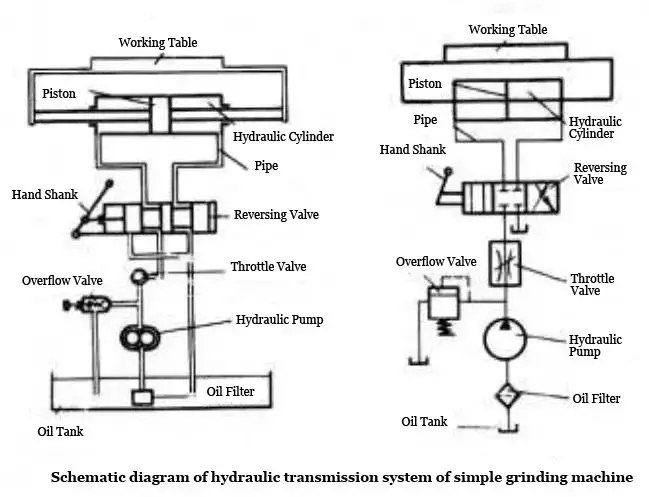
Here is an example of a simple grinder.
The motor drives the hydraulic pump to draw oil from the tank, which transforms the motor’s mechanical energy into liquid pressure energy.
The hydraulic medium enters the left cavity of the hydraulic cylinder through the throttle valve and reversing valve, pushing the piston to move the right side of the table. The hydraulic medium is then discharged from the right cavity of the hydraulic cylinder, flowing back to the tank.
After passing through the reversing valve, the hydraulic medium enters the right cavity of the hydraulic cylinder, causing the piston to move to the left and push the table backward.
The movement speed of the hydraulic cylinder can be adjusted by changing the throttle opening.
The pressure of the hydraulic system can be adjusted using the overflow valve.
When drawing a hydraulic system diagram, symbols are used to represent hydraulic components for simplification. These symbols are called functional symbols.
Basic circuit
A typical hydraulic transmission system comprises various hydraulic components that work together to achieve specific functions.
Any hydraulic transmission system is made up of several basic circuits, each with specific control functions. By combining these basic circuits, the movement direction, work pressure, and movement speed of the actuator can be controlled.
Based on their control function, the basic circuit is divided into three types: the pressure control loop, speed control loop, and direction control loop.
① The pressure control circuit
The pressure control valve is used to control the entire system or a local range pressure circuit.
Based on their function, the pressure control circuit can be divided into four circuits: pressure adjustment, pressure change, pressure release, and pressure stabilization.
② Speed control loop
This loop controls the flow rate of the actuator by regulating the flow of the hydraulic medium. The function of the speed control loop is divided into two parts: the speed regulation circuit and the synchronization loop.
③ Direction control loop
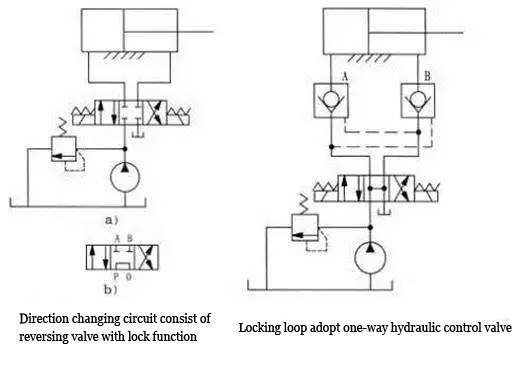
This loop controls the flow direction of the hydraulic medium. The directional control valve controls the movement direction of a single actuator, allowing it to move or stop in both positive and negative directions, which is known as a commutator circuit.
When the actuating element stops, the circuit that prevents external leakage due to loading or other external factors is called a locking loop.
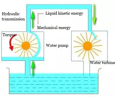
Hydraulic Drive
Hydraulic transmission involves the transfer of energy through liquid kinetic energy, using liquid as the working medium.
The impeller converts the rotational speed and torque input from an engine (such as an internal combustion engine, motor, turbine, etc.) and drives the machine’s working parts via the output shaft.
The fluid and impeller interact with each other in the input shaft, output shaft, and shell, producing a change in the moment of momentum to transmit energy.
Hydraulic transmission differs significantly in principle, structure, and performance from fluid pressure-based hydraulic transmission.
The input shaft and output shaft of the hydraulic drive are only connected to the working medium through liquid, and non-direct contact between components results in non-rigid transmission.
Characteristics of hydraulic drive
Automatic adaptability
The hydraulic torque converter can automatically increase or decrease its output torque with changes in external loads, and the speed can correspondingly increase or decrease, achieving stepless speed regulation within a wide range.
Vibration isolation
Because the working medium between the impeller is liquid, their connection is not rigid, making it possible to absorb shock and vibration from the engine and external load. This ensures stable starting, acceleration, and uniform operation, extending the service life of parts.
Penetration performance
When the pump rotation speed is constant and the load changes, the input shaft (i.e., the pump wheel or engine shaft) changes.
Different types of hydraulic elements can be used to match the engine’s requirements for different work machines, improving mechanical power and economic performance.
The basic principle of hydraulic drive
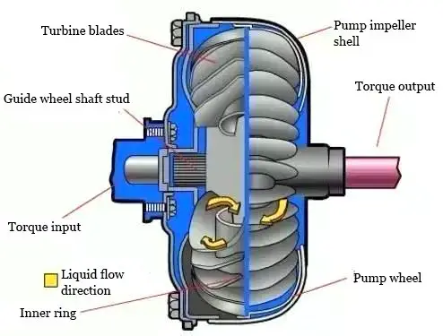
The original power source (such as an internal combustion engine, motor, etc.) drives the pump wheel to rotate, increasing the speed and pressure of the working fluid and converting mechanical energy into liquid kinetic energy.
The working liquid, now with kinetic energy, hits the turbine and releases energy to the turbine, causing it to turn and power the output, ultimately transferring energy.
Hydraulic transmission device
Hydraulic transmission utilizes liquid kinetic energy to transfer energy, and it commonly includes hydraulic couplers, hydraulic torque converters, and hydraulic mechanical components.
① Hydraulic coupler
A hydraulic coupler, also known as a hydraulic coupling, is a mechanical device used to connect a power source (usually an engine or motor) to a working machine to deliver rotational power.
In addition to use in automobiles’ automatic transmissions, hydraulic couplers are widely used in marine and heavy industries.
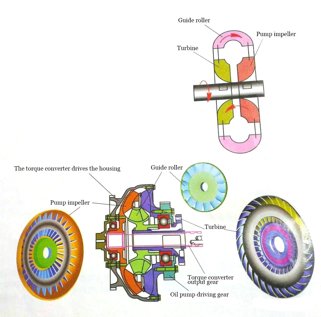
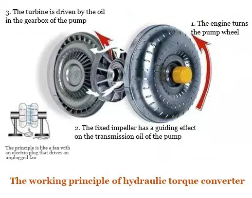
② Torque converter
A hydraulic torque converter is a hydraulic element that consists of a pump wheel, turbine, and guide wheel. It is installed between the engine and transmission and uses hydraulic oil as the working medium to transmit and convert torque, adjust speed, and provide disconnection functionality.
Application of hydraulic drive
The use of hydraulic transmission in modern machinery began in the early 20th century, primarily as ship power equipment and transmission mechanisms between the propellers to solve the issue of limited speed due to high power and high-speed steam or gas turbines suffering from “cavitation.”
Today, hydraulic transmission is widely used in automobiles, tractors, construction machinery, railway locomotives, tank armored vehicles, oil drilling machinery, lifting and transportation machinery, fans, pumps, and other equipment.


I like so much…
I need pdf of hydraulic transmission argent
what about transmision jack??
Great article and illustrations! Solenoid valves are efficiently used to control greenhouse gas emissions during oil supply and transportation. Thus flow rate measurement and leak measurement is important to consider when deploying them.