Introduction
The load on plate roll bending machines is substantial, so the strength of its parts must be high.
Furthermore, with intense competition in the market, reducing the cost of plate rolls is crucial. This means that the machine must be designed with accuracy and reliability.
In order to design the roll bending machine, it is necessary to first perform a force analysis of the rolling machine, which provides the original parameters for designing each part of the machine.
The calculation of the driving power of the main drive system is also important for designing the main drive system and selecting the motor.
As a result, calculating the force analysis and driving power of the plate rolling machine is critical to the design of the roll bending machine.
This post provides one method for calculating the force capabilities of a symmetrical three-roll bending machine, and other types of plate rolling machines can use it as a reference.
Force Analysis
2.1 Maximum torque required for a cylinder rolling
When the plate rolling machine is working, the steel sheet should be rolled into the steel pipe.
At this time, the stress of the material has reached the yield limit.
Therefore, the bending stress distribution on the tube section is shown below the figure (b), and the bending moment M of the section is:
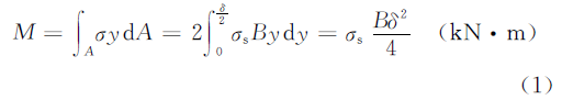
In the above formula,
- B, δ – The maximum width and thickness of rolled steel sheet (m)
- σs – Material’s yield limit (kN • m-2)
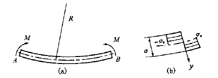
Fig.1 Stress distribution of roll bending
When considering the deformation of the material, there is reinforcement, and the reinforcement coefficient K is introduced to modify the equation (1), namely:
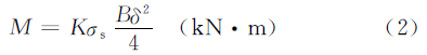
In the above formula,
- K – reinforcement coefficient, the value can be K = 1.10~1.25, when the result for δ/R is big, then take the biggest value.
- R – Neutral layer’s radius of the rolling plate (m)
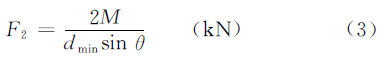
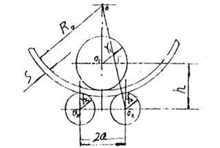
2.2 Force Condition
When rolling steel plate, the force condition is shown as below figure. According to the force balance, the supporting force F2 on the roll plate can be obtained via the formula:
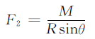
In the above formula,
- θ – The angle between defiled line OO1 and OO2,
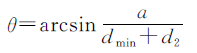
- α – Lower roller center distance (m)
- dmin – Min diameter of plate rolling (m)
- d2 – Lower roller diameter (m)
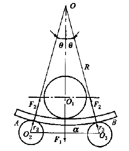
Fig.2 Force analysis of roll bending
Considering that the thickness of the plate δ is far less than the minimum diameter of the rolling tube, the radius R of the neutral layer is around 0.5dmin, in order to simplify the calculation, the above equation can be changed to:
According to the force balance, the pressure force F1, which is generated by the upper roller, acting on the rolling plate is:

Calculation of driving power
3.1 Lower roller drive moment
The lower roller of the plate rolling machine is the driving roller, and the driving torque on the lower roller is used to overcome the deformation torque Tn1 and the friction torque Tn2.
In the process of steel plate rolling, the deformation capabilities stored in AB section of the steel plate (see Fig 1a and Fig 2) is 2Mθ, the costed time is 2θR/V (V is rolling speed).
The ratio is equal to the power of deformation torque Tn1, namely:

Therefore,

The friction torque includes the rolling friction torque between the upper and lower roller and the steel plate, and the sliding friction torque between the roller neck and the shaft sleeve, which can be calculated as follows:
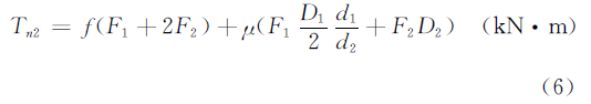
In the above formula:
- f – Coefficient of rolling friction, take f = 0.008m
- μ – Coefficient of sliding friction, take μ = 0.05-0.1d1,
- d2 – Upper roller & lower roller diameter (m)
- D1, D2 – Upper roller & lower roller neck diameter (m)
The size is not yet accurate in the design phase, the value can take Di = 0.5di (i=1, 2). The lower roller drive torque T equals the sum of the deformation torque Tn1 and the friction torque Tn2.
3.2 Lower roller driven power
Lower roller driven power is:

In the above formula:
- P – Driven power (m • KW)
- T – Driven force moment (KN • m)
- n2 – Lower roller rotation speed (r • min-1), n2=2V/d2 (V is rolling speed)
- η – transmission efficiency, η=0.65-0.8
The power of the main motor can be obtained from the value of P.
Hello,
Where did you get all these formulas from? I currently making a report for my school project and my advisor teacher is asking for the formulas references so I can apply them.
from experts in this field.
When showing your calculations for lower roller drive moment (3.1), your calculations appear to drop the V term (rolling speed) with no explanation. The units work out after dropping the term, but not before. Can you explain where this term is used during this step? Equation 5 does not have a clear path from what is shown above it. Thank you
The rolling speed is the speed of sheet
sir i need calculation for 1 inch metal sheet rolling
What’s the minimum rolling diameter of sheet
this is determined by the upper roller diameter
Hello sir
What is the ratio ahe rollrs,if i use to 9 rolling machine,what is the distance between two roller
I would like to bend 100mm X 100mm X 1900 dia ring could you help me with the calculations
You can refer to the calculation formula in this article.
This really answered my problem, thank you!
thank you so much sir this article really helped me
Glad it can help you.
Sir how we can decide the roller diameter if we want to make the pipe of 25- 50 mm diameter from 1.5-2 mm sheet thickness and also please tell us about other design calculations like roller speed, bottom roller distance etc..
I want to buy maschine sustainable to bend 25 mm thick and 150 mm max size
Kindly check your email to check our reply.
explain the eqn.(1) pls.
Do you understand it now?
Where is the explanation for eqn.1 did you sent it on my email ? i cant see it in my inbox.
plz send the explanation of formulas to my email – [email protected]
plz sir it is very important for me.
do you have the same explanation for 2 roll plate bending machine (with urethane (rubber) roll) ?
Currently, we didn’t write this for 2 roll plate bending machine. Will take this into consideration.