The crankshaft is a crucial component of a diesel engine. To guarantee its quality, 100% inspection is performed after it has been manufactured.
Typically, major engine manufacturers have their own set of standards for crankshaft inspection. During this process, various magnetic marks with different shapes, complex origins, and challenging solutions can arise.
The classification of magnetic marks is typically determined by the inspector’s experience, especially when it comes to identifying grinding cracks.
For ease of observation during inspection, crankshaft manufacturers usually perform magnetic particle inspection after grinding. The treatment of cracks, whether through cold or hot processing, remains a topic of debate.
Through years of production and analysis, several typical magnetic inspection marks of induction-hardened crankshafts have been identified, providing a foundation for more informed on-site judgment.
1. Process route of forged steel crankshaft
Blanking → forging → normalizing, quenching and tempering → rough machining → stress relief → semi finishing → induction quenching and tempering → finishing → inspection and warehousing
2. Detection method of crankshaft surface defects
Currently, the most common methods for detecting surface defects in crankshafts are using a fluorescent magnetic particle testing machine or performing a visual inspection.
3. Surface defect magnetic trace
Surface defects are imperfections that can be seen with the naked eye under good lighting conditions after the magnetic suspension is cleaned following magnetic particle inspection. These are referred to as surface defect magnetic marks.
Some common surface defects in forged steel crankshafts include: raw material and forging cracks, heat treatment cracks, grinding cracks, and exposed non-metallic inclusions.
(1) Appearance and identification of raw material cracks and forging fold cracks
Raw material cracks and forging fold cracks are typically small and located on the surface of the forging blank, making them challenging to detect without close examination. However, these cracks can worsen after processing and induction hardening.
In the case of smaller parts, internal stress can cause these cracks to seriously split the part in two.
Raw material cracks are usually parallel to the axis, extending straight and intermittently, as shown in Figure 1.
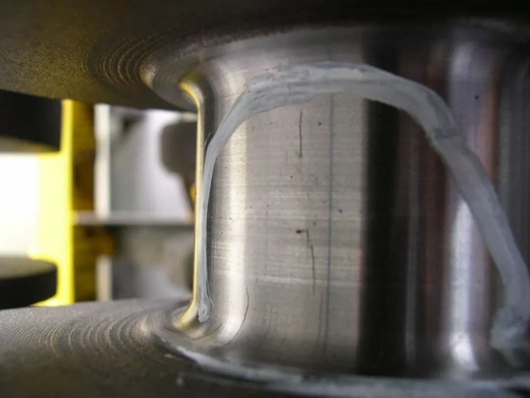
Fig. 1 Raw Material Cracks
Forging fold is an interlayer that results from improper operation during forging. Its shape and location are unpredictable.
After quenching and tempering, the crack becomes relatively large, as shown in Figure 2. In some instances, the involved oxide layer can be seen at the main openings.
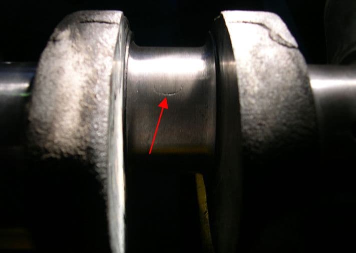
Fig. 2 Forged fold
See Fig. 3 for forgings with cracks.
A rough analysis might be:
① Because of overburn.
② As the soluble metal penetrates into the base metal (such as copper).
③ Stress corrosion cracking.
④ The forging surface is severely decarburized.
These cracks can be further differentiated through process investigation and organizational analysis.
For instance, overheating the steel or having a high copper content in the steel can cause copper brittleness. From a microstructural perspective, copper brittleness cracks occur at the grain boundary.
In addition to cracks, a bright copper mesh can be seen, while only oxides are present at the pure, overburned grain boundary.
Stress corrosion cracking can occur after acid pickling. When viewed under high magnification, the crack extends in a dendritic pattern.
If the forging has been severely decarburized, a thicker layer of decarburization can be observed on the test piece.
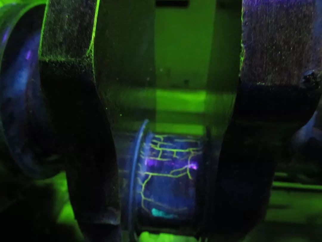
Fig. 3 Forging Cracking
For raw material cracks and forging cracks, during metallographic observation, if samples are taken perpendicular to the cracks, decarburization can be observed on both sides of the cracks. In some cases, oxides may be present in between.
(2) Appearance and Identification of Quenching Cracks
Quenching cracks in crankshafts usually occur in areas with sudden changes in size, thin effective thickness, or poor surface roughness. These areas may include steps, ends, sharp corners, keyways, holes, oil passages, and other structures in the quenching region.
Induction quenching can cause a concentration of induction current in these parts, leading to local overheating and quenching cracks due to a deep hardening layer.
Quenching cracks generally have two forms.
One form of quenching cracks can be found on a smooth cylindrical surface or near a boss with a thin effective thickness. These cracks are distributed circumferentially and have relatively large dimensions, as shown in Figure 4.
The other type of crack is an oil hole crack, as shown in Figures 5 and 6.
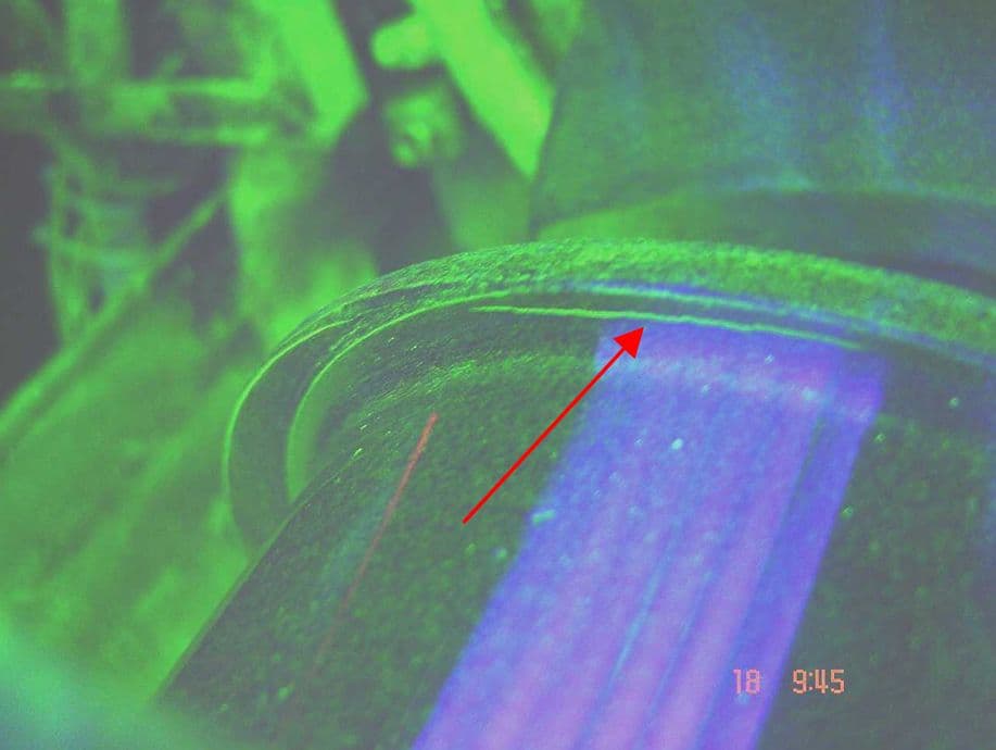
Fig. 4 Cracks on top dead center boss of connecting rod journal
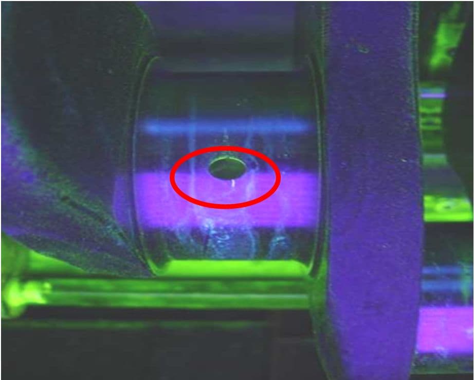
Fig. 5 Radial cracks at oil orifice
Fig. 6 Transverse small cracks on inner wall of oil hole
In addition to radial cracks near the oil hole in the crankshaft, small transverse cracks may sometimes appear in an area 3 to 8mm below the inner wall of the oil hole. Alternatively, “C”-shaped cracks may also be found on the journal surface near the hole, generally appearing as an arc shape 10 to 20mm from the hole edge along an inclined oil passage.
These cracks are a result of the varying thicknesses between the inner wall of the inclined oil passage and the journal surface. The thinnest area is more prone to hardening, leading to a relatively deep hardened layer.
If the quenching process is not properly executed, small transverse cracks may appear in the oil passage hole wall where it is thin and hardened. If these cracks extend to the surface in the form of flakes and penetrate the surface, a “C”-shaped crack at the orifice can form.
Quenching cracks are easily distinguishable from raw material cracks and forging cracks under a metallographic microscope. They do not have decarburization or oxide and have a thin tail end.
If the heating temperature is too high, quenching cracks will be distributed along the grain and exhibit superheat characteristics such as coarse acicular martensite. Quenching cracks caused by rapid cooling in the martensite transformation zone are typically transgranular, with straight cracks and strong lines, and no branching small cracks around.
The metallographic structure near the main crack is typically composed of fine tempered martensite.
(3) Appearance and Identification of Grinding Cracks
After induction hardening, the surface of the crankshaft has high hardness and high internal stress. If the grinding parameters are incorrect, grinding cracks can occur.
The process of grinding cracks is similar to the quenching process.
During high-speed grinding, the local area where the grinding wheel contacts the workpiece reaches temperatures above the austenitizing temperature. The application of cutting fluid during grinding is equivalent to another quenching process.
If the material contains trace alloy elements that increase the likelihood of quenching cracks, the probability of grinding cracks will increase.
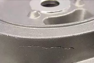
Grinding cracks appear on the smooth, ground surface. Common types of grinding cracks on journals include:
Crack cracks (in the shape of a “Japanese mouth” or well), as shown in Figure 7, which are single linear cracks, multiple parallel point and strip cracks, or a pile of point and strip cracks, as shown in Figure 8.
Single linear cracks or multiple parallel point cracks are distributed in the axial direction, perpendicular to the grinding direction. On the side boss, these cracks are generally radial, as shown in Figure 9.
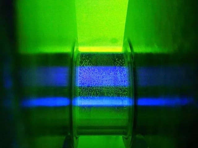
Fig. 7 Cracking
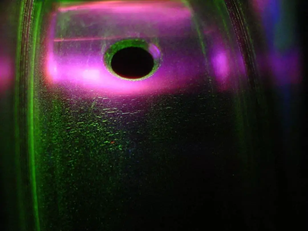
Fig. 8 Multiple Parallel Point and Strip Cracks or a Pile of Point and Strip Cracks
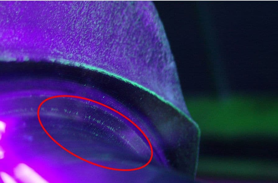
Fig. 9 Lateral radial cracks
If a sample is taken perpendicular to this type of crack, the secondary quenching structure can be observed under a metallographic microscope.
The metallographic characteristics of the secondary quenching layer from the outside to the inside are a white bright layer, a black-gray tempered layer (troostite), and the induction hardening layer (tempered martensite).
The size of the hardness indentation of the white bright layer can be used to determine its hardness, which is particularly high, as shown in Figures 10 and 11.
In some cases, only the tempered troostite layer can be seen and the white bright layer of secondary quenching cannot be seen.
The secondary tempering layer is very thin, requiring high sample preparation standards for metallographic samples. If the sample preparation is not done properly, the white bright layer may not be visible.
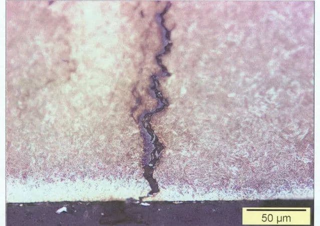
Fig. 10 Metallographic Structure of Secondary Quenching Layer for Grinding Cracks
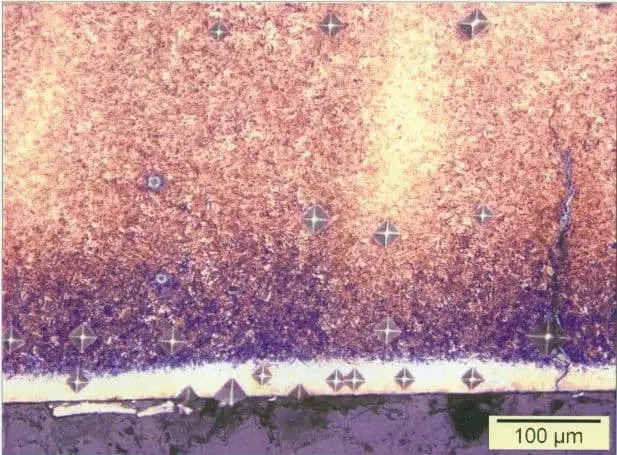
Fig. 11 Comparison Diagram of Hardness Indentation of Secondary Quenching Layer for Grinding Cracks
(4) Appearance and identification of exposed non-metallic inclusions
The inclusions in steel are generally categorized into two types: metallic and non-metallic inclusions.
Metallic inclusions, which are typically external, can be prevented by implementing strong management practices and adhering to strict operational procedures.
On the other hand, non-metallic inclusions are formed by the reaction of gases in steel, deoxidizers, and alloy elements during smelting, as well as the presence of refractory fragments.
To remove these inclusions during smelting, the liquid steel is fully boiled and stabilized in the steel ladle so that the inclusions can rise to the surface and be removed in the slag.
The position of non-metallic inclusions is not fixed and they can occur either singly or in clusters. As non-metallic materials are non-magnetic, their presence disrupts the continuity of the material.
If inclusions are exposed or if they are relatively close to the surface, they will appear as magnetic marks in magnetic particle flaw detection. The closer the inclusions are to the surface, the more prominent their magnetic trace will be. As a result, the magnetic traces of inclusions may be intermittent.
After forging, non-metallic inclusions are often distributed along the axial direction of a crankshaft. The lines of their magnetic traces appear soft and the end is usually bald. When an inclusion is exposed after processing, it is considered an open defect (refer to Figure 12).
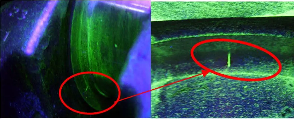
Fig. 12 Single open inclusion and enlarged morphology
A sample is taken perpendicular to the crack and examined under a metallographic microscope.
The depth of the crack is not deep and its bottom has a round shape, as shown in Figure 13.
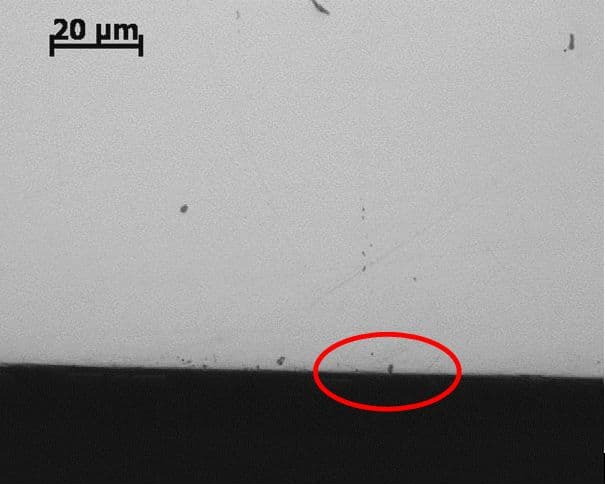
Fig. 13 Cross section without corrosion
4. Appearance and identification of non surface defect magnetic traces
After conducting magnetic particle flaw detection, the magnetic suspension should be wiped clean and observed with the naked eye under good lighting conditions.
If no defects are visible, the magnetic mark is considered a non-surface defect.
(1) Forging streamline
During the forging process of forged parts, the metal flows in a specific direction.
By dissecting the part, the forging flow lines can be observed through macro observation after undergoing corrosion, as shown in Figure 14.
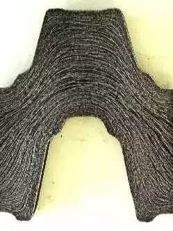
Fig. 14 Macro picture after 5% nitric acid alcohol corrosion
During normal flaw detection procedures and as per specifications, a forging flow line magnetic trace is generally not visible or is very weak, as demonstrated in Figure 15.
It is only when the magnetic field is too strong or if there is segregation and a significant amount of inclusions present that a clear magnetic trace can be seen.
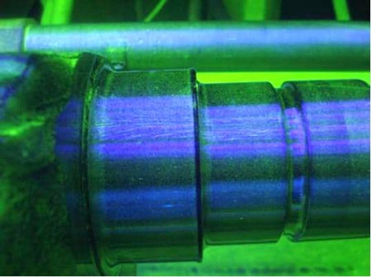
Fig. 15 Front end streamline of crankshaft
(2) Segregation and inclusion
The non-uniformity of the chemical composition of different steel grades is referred to as segregation.
Segregation can be further divided into dendritic segregation, square segregation, and point segregation based on the causes and manifestations.
Ingots, particularly those made of medium carbon chromium molybdenum or chromium nickel molybdenum steel forgings, often contain many inclusions, which are unavoidable.
Adding alloy elements to steel typically reduces its fluidity, making it more challenging to remove non-metallic inclusions in alloy steel compared to carbon steel. This also increases the likelihood of segregation or inclusions.
During the processing of an alloy steel crankshaft, metal flows from the center to the parting surface, resulting in segregation (ribbon) and inclusions that are generally more severe at the trimming surface and closer to the surface.
Even if these inclusions are not exposed at the cutting edge, if they are close to the surface and have a certain length, streamline magnetic marks will appear during flaw detection, as demonstrated in Figure 16.

Figure 16 depicts the streamline at the trimming of a stereo parting crankshaft and strip segregation on the surface after undergoing macroetching with 5% nitric acid.
Alloy steel is known for its high hardenability, which makes it prone to producing structural inhomogeneity (banded structure) during cooling.
Furthermore, alloy steel has relatively poor thermal conductivity, leading to increased residual stress in the steel.
If the grinding process is not properly executed, grinding cracks may occur in areas affected by these metallurgical defects.
5. Conclusion
Correctly identifying all types of magnetic marks in crankshaft flaw detection requires both extensive field experience for flaw detection workers and a unified understanding.
Currently, each engine factory has its own standard for crankshaft flaw detection.
There is varying understanding among professional manufacturers regarding the impact of non-surface defect magnetic marks on the crankshaft fillet and journal and its effect on crankshaft fatigue performance. Further research in this area is needed among industry peers.