Foreword
Please keep the manual and other annexes in a safe place for future reference.
The manual covers important safety information, operating procedures, transportation and storage, installation instructions, usage and applications, troubleshooting, maintenance and service, etc. for the product.
The manual is intended for the standard configuration of our company’s products. Please refer to the additional detailed files for specific components.
Before using this product for the first time, please read the manual carefully.
For efficient use of the product, the operating personnel should:
- Have a basic understanding of computer software such as SolidWorks and AutoCAD.
- Have knowledge of optics and maintenance and repair of electromechanical equipment.
- Ensure they are familiar with the operating process before starting the equipment.
Please note that due to ongoing product updates, the product you receive may differ slightly from the description in the manual. We apologize for any inconvenience this may cause.
Chapter I Equipment Acceptance and Placement
Equipment acceptance and inspection
Notes for unpacking
Please inspect the exterior packaging of the laser cutting machine for any signs of damage upon receipt of the product.
The machine comes packaged in a wooden case and is marked with shock-proof and tilt-proof labels, as depicted in Figure 1-1.
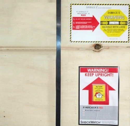
Figure 1-1 Shockproof and Inclination-proof Labels
In the event that the crystal tube on the DAMAGE X (shock-proof) label turns red, it indicates that the machine has experienced shock during transportation or handling.
If the window of the TILT XTR (inclination-proof) label turns red, it indicates that the machine has been subjected to inclination during transportation or handling.
As shown in the comparative figure 1-2, the normal labels are depicted in the upper images, and the ones in which the crystal tube and window turn red are shown in the lower images.
If the crystal tube or window turns red, or if there is visible damage to the exterior packaging, please contact either the insurance company or our company to discuss next steps.

Figure 1-2 Changes of the Labels before and after Shock and Inclination
The equipment is packaged in wooden crates. Before removing the straps, the wooden panels should be removed from top to bottom to prevent damage to the equipment inside the case.
Sharp objects should not be used to puncture the protective film covering the equipment, as this can result in surface scratches and damage to the electrical circuit. Our company will not be held responsible for any damage caused by the customer.
Notes:
Typically, the laser source is housed within the wooden case and must be carefully unpacked to avoid damaging the fiber-optic cable.
For optimal protection of the lathe bed, the packaging should not be opened until a suitable placement position has been determined.
Inspection contents
Please verify that the product you have received is the one you purchased, inspect it for any damage incurred during transportation, and ensure that all components are present and undamaged.
In the event of transportation damage, discrepancy in the product model, or missing accessories, please contact our company promptly.
Installation requirements and notes
Ground requirements
The foundation for the equipment installation must be level, and the difference in altitude between components such as the lathe bed, water chiller, control cabinet, automated loading device, tooling feeding platform (for the robot), and laser source (cabinet-style) should not exceed 10mm.
The thickness of the concrete for the overall installation surface should not be less than 200mm, with a compression strength of no less than 30N/mm2 and a load capacity of more than 30KN/m2.
The overall installation surface of the lathe bed must be composed of a flat, continuous bottom plate within the range of the supporting points. The newly-constructed bottom plate/pressure plate should be free from dents or cracks under normal drying conditions. The laser beam’s travel range on the lens should not exceed 0.5mm due to the incline of the lathe bed.
Environmental requirements
- Ambient temperature and humidity requirements
The equipment must be operated in a dry and well-ventilated environment, with an ambient temperature ranging from +4℃ to +33℃.
It is recommended that the customer provide a stable environment with consistent temperature and humidity for the equipment, if possible.
The ambient temperature should not drop below +4℃ when the equipment is in a shut-down state.
Notes:
To prevent heat distortion, direct sunlight on one side and cool air on the other side should be avoided (for example, if the equipment is located near a window, shutters can be used to mitigate these conditions).
- External air
To maintain optimal cutting quality, it is essential to ensure that no substances capable of absorbing rays with a wavelength of 1.064um are present in the vicinity of the machine, such as steam-containing solvents emitted during painting or steam released from an oil removal device.
- Cooling of control system
The control system is cooled through internal air circulation within the control system casing, ensuring that electrical components are protected from dust and debris to the greatest extent possible.
The control system should not be operated in a damp environment, as this may cause corrosion at the contact points between the contactor and relay.
- Vibration requirement
To maintain optimal performance, it is important to ensure that the equipment is not subject to external forces.
External forces that can impact equipment operation include:
- Forklifts and other land-based vehicles
- Direct installation or removal of other machines near the equipment
- Machines that generate vibration near the equipment, such as punch presses, bending machines, and sheet metal cutting machines.
Placement of components
It is important to plan the placement of the water chiller, control cabinet, laser source, lathe bed or gantry beam (for the robot), and other components. The placement guidelines for these different machines are generally similar and can be found in the layout of various models in the first volume of the manual.
Lathe Bed
The placement of the lathe bed should be confirmed first. A forklift or other tool can be used to lift the lathe bed approximately 80cm to install the base angle.
It is important to make sure that the lathe bed is placed in the intended location (Figure 1-3), after which the packaging of the lathe bed should be removed. The discarded packaging materials should be placed in a designated area designated by the customer on-site and promptly cleared.

Figure 1-3 Machine Lathe Bed (with envelope)
The nuts on the base angle should be adjusted individually (Figure 1-4), and a level gauge or level bar can be used to level the platform of the lathe bed.

Figure 1-4 Base Angle
When installing components such as exchange platforms, outer covers, pipe cutting equipment, and automated feeders outside the lathe bed, the following principles should be observed: from large to small, and from the inside to the outside. Each component should be securely connected after being properly placed.
The RC series manipulator cutting machine should be lifted with a crane, with a rope tied to the lifting bolt of the device, as shown in Figure 1-5.
Please note that the crane load and lifting rope must have a capacity of over 300kg.

Figure 1-5 Hoisting Schematic Drawing for RC Series Manipulator Cutting Machine
Transportation and handling methods and guidelines:
- Climbing on or placing heavy objects on the packaging box is not allowed.
- The product should not be moved by pulling on the cable connected to it.
- Collisions and scratches on the panel and display must be avoided.
- The packaging box should be kept free from moisture, prolonged exposure to sunlight, and rain.
- The manipulator must be handled with care during installation, avoiding any collisions. The wire rope should not come into direct contact with the equipment and, if necessary, a soft object should be used as a separator.
Water Chiller
The water chiller is equipped with wheels, making it easy to move to an appropriate location after being filled with water in a large open space.
It is suggested to place it to the right diagonal rear of the lathe bed (with the user facing the machine).
Notes:
- The unit should not be installed in a non-ventilated enclosed room. The distance from the top of the unit to other objects must be at least 2.5m to ensure proper airflow and to prevent blockage, while the distance from the water chiller to other objects around it must be at least 1.5m to prevent hot air from the water chiller from flowing back to the air inlet surface.
- The water chiller should only be filled with purified, distilled, or deionized water, and no corrosive liquids, anti-freezing solutions, or turbid (with filiform, flocculent, or granular suspended solids) water or water with an unpleasant odor should be used.
- Avoid direct contact with the water (such as with hands) when filling it, and only use pumps and hoses designated for this water chiller.
- It is recommended to replace the water in the water chiller every two to three months.
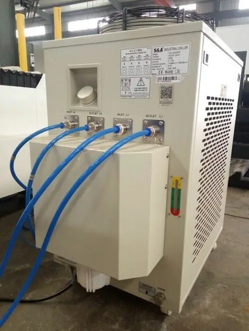
Figure 1-6 Water Chiller
Laser source
The size of the laser source will vary depending on the power output. The laser source with a power output lower than 1000W can be housed inside the control cabinet (refer to Figure 1-7, Figure 1-8, and Figure 1-9).

Figure 1-7 Open the Front Door of Control Cabinet

Figure 1-8 Setting Schematic Diagram of the laser source
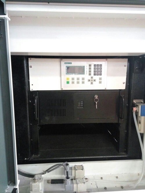
Figure 1-9 Setting Position of I3 and I5 Series laser source
Laser Source
If the power output of the laser source exceeds 1000W, it will be housed in a cabinet with wheels that cannot be accommodated inside the control cabinet. The cabinet should be placed in the middle at the right side of the lathe bed.
The I3 and I5 series are equipped with a small cabinet, and the power output of the laser source is typically small, so the laser source can be placed in a designated position inside the cabinet (refer to Figure 1-9).
The RC robot model is unique, with a power output of the laser source lower than 1000W, and the laser source can be placed in a designated position inside the cabinet (similar to Figure 1-7, Figure 1-8, and Figure 1-9).
Control Cabinet
If the laser source can be housed inside the control cabinet, it should be placed in a designated location in an open space. The optical fiber and wire should be laid gently on the main body. The control cabinet should then be pushed to the right front side of the lathe bed.
Fan
The fan is used to remove smoke generated. The fan duct interface can be seen when the upper cover of the lathe bed is opened.
The other end of the pipe is connected to the fan, and a gas outlet pipe is equipped with the fan. This allows for flexible fan installation, provided the pipe length allows.
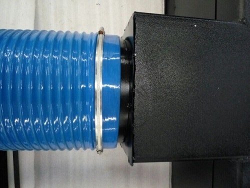
Figure 1-10 Interface for Installing Fan at Back of Lathe Bed
Installation introduction of pipe cutting machine
Our company produces a variety of pipe cutting machines, each equipped with multiple holding device configurations.
For plate and tube machines, it is crucial to maintain the parallelism, perpendicularity, and flatness of pipes and laser cutting heads for optimal performance. This operation can be complex and requires the operator to have a strong level of operating skill.
We strongly recommend that operating personnel attend training at the factory or request on-site assistance from our company’s customer service staff for installation and commissioning.
The installation of a general pipe machine is similar to that of a plate machine, please refer to the previous chapter for more information.
Chapter II Connection of Pipeline, Line and Other Components
Gas circuit connection and gas requirements
Gas circuit connection
Two white gas lines will be connected to the lathe bed, one for nitrogen and one for oxygen.
A nitrogen gauge can be used to connect the nitrogen line to the nitrogen-providing device (air). An oxygen gauge can be used to connect the oxygen line to the oxygen-providing device (refer to Figure 2-1).

Figure 2-1 Example for Connection of Gas Supply Device
The RC robot series can only be equipped with an oxygen circuit.
Using gas cylinders is a convenient method for supplying assisted gas, but it requires manual labor when consumption is high.
Avoid completely depleting the gas cylinder during operation. When returning the cylinder, the residual pressure must be at least one and a half times greater than the air pressure.
Cut off the air flow by stopping the cutting operation when replacing the gas cylinder.
Liquid storage tanks can be selected based on processing conditions and are the easiest and most economical method for air supply.
| Assisted gas | Purity | Main applied sheet metal |
|---|---|---|
| Oxygen (O2) | 99.95% | Carbon steel |
| Nitrogen (N2) | 99.95% | Stainless steel |
| Air | Clean (free of water, oil and other impurities) | Thin carbon steel and thin stainless steel |
In order to ensure proper operation, variables related to the assisted gas, such as nozzle diameter, assisted gas pressure, and laser cutting time, must be taken into account when calculating the actual gas consumption.
Note:
As standards for nitrogen and oxygen gauges may vary by state and region, the user may need to purchase a nitrogen gauge and oxygen gauge locally if the ones provided by our company are not compatible with the gas supply device. The temperature of the used gas should not exceed 50℃. For any issues related to the gas supply, please contact the gas supplier. If the gas supply is located far from the machine, the gas circuit and electrical cable should not be run in the same pipeline and the gas should be introduced to the machine tool separately. Only trained professionals should be allowed to operate the machine, and the pipes should be cleaned and tested before use to ensure proper connection.
The sheet metal cutting machine is equipped with a pneumatic butt material device, which can be seen as a pair after opening the cover (refer to Figure 2-2). Other pneumatic devices may be of a special model, so it is recommended to use compressed air.

Figure 2-2 Connection of Pneumatic Actuator
Connection of water circuit and water chiller
The HP and LP water circuits are output from the water chiller. The LP water circuit (two blue pipes to the lathe bed, as shown in Figure 2-1) flows to the fiber pigtail and cutting head, and it is important to note the water inlet and outlet directions. The water should flow through the fiber pigtail before reaching the laser cutting head.
The LP water circuit also flows (Figure 2-3) to the laser source, and the connection modes will vary depending on the brand and type of the laser source. It is important to note the flow direction and label to ensure the correct connection of the water pipe to the machine.
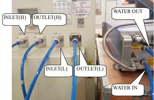
Figure 2-3 Example for Connection between Water Chiller and laser source
For example, as shown in Figure 2-3, the OUTLET (L) interface on the left side of the water chiller should be connected to the WATER IN interface on the right side of the laser source, and the INLET (L) interface of the water chiller should be connected to the WATER OUT interface to ensure the circulation and flow of water.
Circuit connection
The machine consists of multiple parts, and it is important to ensure that all parts are properly connected. The electrical connection method can be referred to in the electrical schematic diagram in the first volume of the manual.
Water Chiller:
In the control cabinet, the power line for the water chiller and the laser source power line (as shown in Figure 2-4) should be connected and securely fixed, along with the hot wire, neutral wire, and ground wire.

Figure 2-4 Example for Connection between Water Chiller Power Line and laser source Power Line
If the machine uses a laser source with higher power, the water chiller’s cooling capacity will increase and require a three-phase power supply. The connection must be done separately, taking note of the phase sequence. If the phase sequence is incorrect, the water chiller will trigger an alarm and fail to start. Some models of the water chiller may also have a signal line that needs to be connected to the laser source. The connection should be made based on the label.
Laser source and laser cutting head
Same in principle as the water chiller, the laser source’s fire line, zero line, and grounding line should be connected in the control cabinet. If the laser source has a larger power, a three-phase power supply should be provided, and the main line should be connected separately.
Different laser sources of different brands or models will have different phase sequences; if the phase sequence is incorrect, the fiber sequence will alarm and will not be activated.
A signal line from the laser source must be connected to the control card. The number of connection lines for laser sources of different brands and models will vary, and the reserved interface in the control cabinet should be found and connected according to the line number.
If there are any problems with the connection, the user can refer to the connection diagram in the first volume of the manual, or they can directly contact our company for assistance.
Examples of signal line connections for the laser source are shown in Figures 2-5 and 2-6.
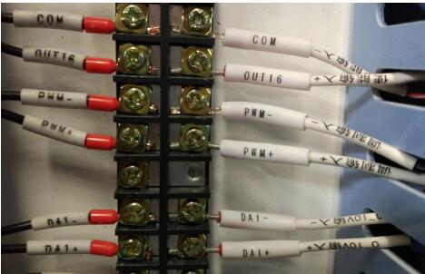
Figure 2-5 Example for Connection of laser source Signal Line 1
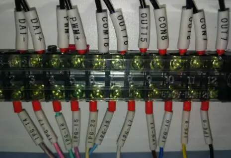
Figure 2-6 Example for Connection of laser source Signal Line 2
The water chiller of some models will have a signal line introduced to detect if the water chiller is turned on. The connection should be made according to the label.
The laser source’s optical cable should be carefully passed through the tank chain and the fiber pigtail should be inserted into the laser cutting head and secured at the Z-axis. The water pipe, gas line, amplifier, and sensing line should be installed after the laser cutting head is secured. Detailed operation instructions can be found in the accompanying materials.
The following is a brief overview of the operation procedures:
- Remove all the cover plates of the tank chains.
- Release all the laser source’s optical cables to relieve any tension.
- Run the fiber pigtail through the hole in the control cabinet and into the tank chain, ensuring that it extends 300mm to 400mm from the laser cutting head’s shield.
- Insert the fiber pigtail into the laser cutting head.
- Secure the laser cutting head at the Z-axis.
- Install the water pipe, gas line, amplifier, and sensing line based on their labeled numbers, as shown in Figure 2-7.

Figure 2-7 Example for Installation of Fiber Cutting Head
- Install the cover plate of tank chain.
- Recover the excessive optical cable and put it on the laser source shell.
Notes:
The end of the fiber pigtail must be clean before inserting it.
A special microscope component can be used to inspect the end of the fiber pigtail, and a special cleaning agent (isopropyl alcohol), compressed air, special cotton swab, and lens paper should be used to clean any dust or debris.
Bending the optical cable of the laser too much is strictly prohibited to avoid breaking the glass fiber inside the cable.
The optical cable should not be left exposed to avoid being stepped on.
Plugging the Fiber Pigtail into the Laser Cutting Head:
Lay the fiber pigtail horizontally, remove the black dust cover, and align the golden marked point with the red marked point on the chuck of the laser cutting head. Insert it into the bottom.
Turn the nut to the left according to the instructions marked on the chuck of the laser cutting head, lift it, and turn it to the left to complete the fixation and fastening process.
Removing the Fiber Pigtail from the Laser Cutting Head:
The process of removing the fiber pigtail is the opposite of the installation process. Turn the nut on the chuck of the laser cutting head to the right, pull it down, and turn it to the right. The fiber pigtail will then be in a free state and can be removed from the chuck.
Once the fiber pigtail has been separated from the laser cutting head, dust covers should be used to cover each one separately to prevent dust from entering.
Please pay attention to distinguish between the water pipe and the gas line.
In general, the white rigid pipe is the gas line, and the white and blue pipes are the water pipes.
The methods of connecting the water pipe to different types of laser sources will vary, and the connection should be made based on the label.
Control cabinet
To ensure normal operation of the machine, multiple lines must be introduced into the control cabinet, such as the power line of the water chiller, power line of the laser source, and signal line of the laser source. The control cabinet also requires the introduction of other lines (Figure 2-7); some lines are inserted into ports while others are directly connected to the electrical components within the control cabinet. All lines are labeled, and connections should be made based on these labels.
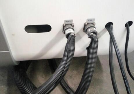
Figure 2-7 Example for Line Introduction of Control Cabinet
In case of any connection problem, please refer to the connection diagram in the first volume of the Manual.
Fan
The control cabinet also has a reserved connection position for the fan power line near the laser source power line and water chiller power line. The positions marked with labels U1, V1, and W1 in the control cabinet should be connected to the corresponding U1, V1, and W1 positions on the fan, as shown in Figure 2-8. If there is a motor inversion, it indicates a wrong phase sequence, and the phase sequence connection should be re-connected after cutting off the power.
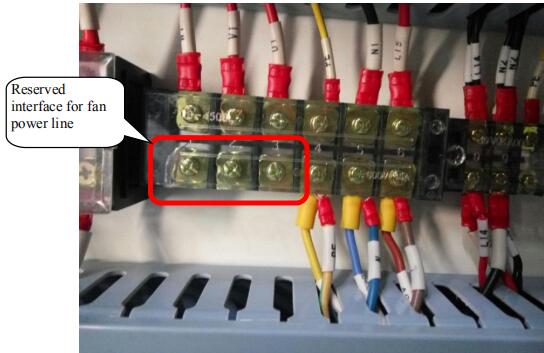
Figure 2-8 Connection Position for Fan Power Line
Connection of other circuits
The machine may have additional functions that need to be connected in order to ensure normal operation. These lines will be marked with labels, and the connection should be made according to the labels. If you have any questions about the connections, please contact our company.
Circuit connection of main power of the machine
It is important to ensure that the machine can be turned on only after all pipes, lines, and components are properly connected. The main power line of the machine, excluding the I series, is a five-core cable (Figure 2-9) consisting of a black ground line, a blue neutral line, and three phase lines in different colors (yellow, green, and red).

Figure 2-9 Main Power Line
It is necessary to make sure that the machine can only be powered on after all pipes, lines, and components have been properly connected. The main power line of the machine, except for the I series, is a five-core cable, including the black grounding line, blue zero line, and three other colored phase lines (yellow, green, and red). The main power line of the I series is a three-core cable, consisting of the fire line, zero line, and grounding line. All cables are marked with labels, and connections should be made based on the numbered lines.
Notes on Electrical Safety:
It is important to ensure that all equipment voltage complies with the machine requirements, and the power line should be securely fixed with a short-circuit switch to prevent damage to the equipment from power shortages. The housing of each piece of equipment should be grounded to prevent static electricity from damaging the electrical components, as well as to protect operating personnel from electric shock if a circuit is damaged and causes a leak.
When performing maintenance or replacing electrical components, the power should be turned off, and the operator should wait for a period of time before beginning. Hot line work is strictly prohibited. The circuit breaker, transformer, and connection plate should be cleaned regularly to prevent current from passing through any dust and causing damage to the equipment. Finally, after completing the work, the power supply should be turned off.
Chapter III Start-up Test Run
Knowing various switches on the machine
The switch is located on the control cabinet, as shown in Figure 3-1. Its appearance may vary depending on different batches, but its functions are briefly described as follows:

Figure 3-1 Schematic Diagram of Each Switch of Control Cabinet
The machine’s switch is located in the control cabinet as depicted in Figure 3-1. The appearance may vary between different batches, but its functions are briefly described as follows:
Main Switch of the Machine: The machine will be ready to operate once the main switch is closed after properly connecting the power line.
Water Chiller and Laser Source Switch: When the water chiller and laser source switch is closed, both the water chiller and laser source will be prepared for operation.
Computer Switch: Once the computer switch is closed, the control panel for the height-adjustment device will light up, and the computer controlling the machine can be started by clicking the start-up key on the computer host.
Height-Adjustment Device Control Panel: This panel is used to calibrate the sheet metal to stabilize the cutting process, and it will be displayed in the control software.
Emergency Button: The machine will stop operating if this button is pressed during movement to prevent potential danger. For added safety, there is another emergency button located at the bottom right of the displayer, and both buttons should remain unpressed during normal operation.
Servo Drive Switch: Each axis of the machine will be prepared to work when this switch is closed.
USB Port: A USB port is provided for the computer host to connect with U-disks and other equipment.
Other switches are integrated into the software and can be operated in the CNC tab. The display may vary between different machine models, as shown in Figure 3-2.
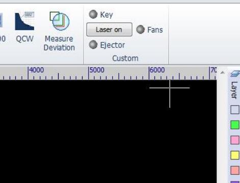
Figure 3-2 Buttons of CNC Tab
Ejector: The action of the pneumatic actuator and roller lift for facilitating loading is controlled by the butt material device switch.
Fans: The fan switch can be clicked to start the fan and enable the smoke evacuation and dust removal function. The “Key” and “Laser on” buttons are used for operating the laser source, which will be described later.
Note: If the lines, gas circuit, and water circuit are not connected or not properly connected, the switches mentioned above may not function.
Furthermore, the machine is equipped with a remote control handle, and its key functions are described as follows.
Checking whether the moving components operate normally
Please ensure that the connections of the water circuit, gas circuit, and electrical circuit are completed and that the tightening ring, connector, terminal, and switches are connected firmly and reliably.
To start the machine, close the main switch, then the computer switch. Next, click the start-up button on the computer host and press the switch button on the servo drive (or close the servo drive switch on the control cabinet). Finally, open the software controlling the machine (if there is a prompt to return to the origin, please cancel it).
Check if the machine can move the dolly and Z axis vertically and normally, as shown in Figure 3-3.

Figure 3-3 Position Controlling Action in the Software
In order to ensure proper operation of the pipe cutting machine, it is necessary to ensure that all connections of the water circuit, gas circuit, and electric circuit are completed and securely fastened. After turning on the main switch of the machine, the computer switch, and starting the software, test the movement of the dolly and the Z axis. If the machine is equipped with additional functions, be sure to test these as well. If an alarm appears regarding the Z axis, it can be solved through calibration. Machines with outer covers have a cover opening protection function, so be sure to test this after ensuring that the covers are closed. If any other alarms occur, locate the problem area and contact the company if it cannot be resolved. After all actions have been confirmed as normal, initiate a return to origin operation. If prompted, click ‘OK’.
Checking the water circuit
- Close the switch of the water chiller and laser source on the control cabinet.
- Turn on the switch button of the water chiller. (Note: Depending on the model, you may need to also press the start button on the panel.)
- Check all interfaces of the water circuit for any signs of water leakage.
- If you notice water leakage, immediately turn off the water chiller and repair the leaking area.
- Repeat this process until the water leakage has stopped completely.
Checking the gas circuit
Firstly, ensure that there is enough gas in the gas supply device, and check that all gas circuits and connections are secure.
Turn on the switch for the gas supply device and the switches for the oxygen gauge and nitrogen gauge, respectively.
It is recommended to adjust the oxygen gauge to between 0.3-1.0Mpa and the nitrogen gauge to between 1.5-2.7Mpa. In case of any gas leaks, locate the source and resolve the issue.
Once there is no gas leak, click “Puff” in the operating software to check for gas release, and then click “Puff” again to confirm that the gas release has stopped, as shown in Figure 3-4.
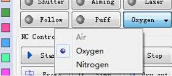
Figure 3-4 Position Testing Gas in Software
Replace the gas by pressing the button on the right side of “Puff.” Click “Puff” to see if there is any gas release, and then click it again to check if the gas has stopped.
If there are any abnormalities, they should be addressed.
After connecting compressed air to the dyad (which can be found by opening the back cover, as shown in Figure 2-2), press the butt material button (or the butt material button at the CNC interface) to test the butt material device on the sheet metal cutting machine.
If the machine is equipped with another pneumatic actuator, it should also be tested.
Laser generation
In general, the water chiller should be started first, followed by the laser source.
Once the water chiller and laser source are ready, turn on the switch on the water chiller. Once the water is flowing normally, turn on the key switch and button switch of the laser source.
Please keep the following alarms in mind:
The laser source should be turned on only when the water temperature has reached 20℃. Depending on the model of the water chiller, it may be necessary to press the start button on the panel after turning it on to start the water chiller. The operating methods may vary based on the power, brand, and type of the laser source.
For instance, the 500W-1000W IPG laser source does not have a button. Its key switch and switch button are integrated into the operating software.
Additionally, for laser sources with larger power, it is important to first turn on the key switch or rotate the handle switch to activate the dehumidification device of the laser source for ten minutes. Then, turn on the water chiller to reach a specific temperature before enabling the laser source to generate the laser.
If an IPG laser source with power under 1000W is used, click the CNC tab before generating the laser. Then, click “Key” (at this point, the POWER instruction light on the laser source panel will turn on), wait three seconds, and click “Laser on” (the PS ACTIVE indicator light on the laser source panel will turn on). Next, click “Aiming” and you will see the red light indicator under the cutting head nozzle.
At this point, click the “Laser” button and the laser will be released from the nozzle (the EMISSION indicator and laser generation indicator light on the laser source panel will turn on), as shown in the following figures.

Figure 3-5 Position Controlling Laser in the Software

Figure 3-6 IPG laser source Panel

Figure 3-7 Red Light Release under the Laser Cutting Head
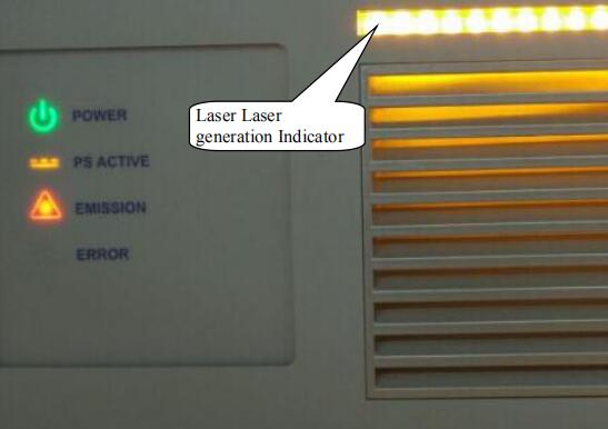
Figure 3-8 Panel Display in IPG laser source Laser generation
Notes:
The laser generation method for this laser source is similar to that of other brands and models, some of which may be easier to use.
For example, after turning on the key switch for a MAX laser source with power under 1000W, wait a few seconds and then click START. If there is any red indicator, click the “Laser” button in the software to release the laser from the nozzle.
For some laser sources, after turning on the key switch (or rotating the key switch to the REM position) and clicking START (or not clicking), it may be necessary to click “Shttur” in the software and then click the Aiming and Laser buttons.
Due to the various brands and models of laser sources, other operations will not be listed in detail. If you encounter any unknown issues, please contact our company.
Start-up and shut-down procedures
This chapter covers the preliminary steps before starting the operation. There are no strict requirements for starting up each component, and the recommended procedure is as follows:
- Host and operation software
- Gas supply device
- Water chiller
- Laser source.
The recommended machine shutdown procedure is:
- After completing the processing, close the gas supply device and separately click “Puff” to release the gas from the gas line.
- Place adhesive tape under the cutting head nozzle to prevent dust in the air from entering the cutting head.
- Move the X and Y axes to the middle of the machine tool to prevent the drive shaft from affecting the cutting precision due to gravity deformation.
- Turn off the switch on the laser, then cut off the power supply.
- Turn off the switch on the water chiller, then cut off the power supply.
- Close the control software and shut down the computer host.
- Check the surrounding environment of the machine tool for any potential fire hazards, such as kindling or high temperature objects, to eliminate safety risks.
Chapter IV Operation Steps for Sheet Metal Processing
Laser cutting process principle
Laser cutting is a sophisticated cutting process that is widely used in material processing. It utilizes a laser beam with high energy density as a “cutting tool” to perform hot cutting on materials.
This technology is used to cut various metals, non-metallic sheets, and composite materials and is widely applied in various fields.
Laser cutting principle
Laser cutting involves the use of a focused laser beam that is directed at the workpiece. The beam melts, carburizes, and ablates the material, or raises its temperature to the point of ignition. Simultaneously, a high-speed stream along the same axis as the light beam is used to remove the molten material and accomplish the cutting.
Laser cutting is a method of thermal cutting.
Main mode of laser cutting
Laser Melting Cutting:
Laser melting cutting refers to the process of using laser heating to melt metal materials, and using a non-oxidizing gas (such as N2 or air) that is expelled through a nozzle along the same axis as the light beam to remove the liquid metal and form a kerf due to the strong pressure.
Laser Oxygen Cutting:
The principles of laser oxygen cutting are similar to those of oxyacetylene cutting. In this process, the laser is used as the preheating source, and oxygen and other active gases serve as the assistive gas.
On one hand, the expelled gas oxidizes with the metal, releasing a large amount of oxidation heat.
On the other hand, the melted oxide and melt are blown out from the reaction area, resulting in the formation of a kerf in the metal.
Laser oxygen cutting is mainly used for easily oxidized metal materials, such as carbon steel. It can also be used to process materials like stainless steel, but this results in a black and rough cross-section, and the cost is lower than that of using an inert gas.
Features of laser cutting
Laser cutting is known for its quick cutting speed and high quality compared to other cutting methods. The key features of laser cutting are:
- Laser cutting provides excellent cutting quality due to its small laser spot, high energy density, and fast cutting speed.
- The incision is narrow, with both sides of the kerf parallel and perpendicular to the surface. The size precision of the cut parts is high, and the cutting surface is smooth, clean, and attractive. In some cases, laser cutting can serve as the final processing step, allowing the parts to be used directly without any further machining.
- The width of the heat-affected zone in the material is small after laser cutting, which minimally affects the material’s properties near the cut. The workpiece experiences minimal deformation and maintains high cutting precision.
- Laser cutting is fast, resulting in high work efficiency.
- In non-contact cutting, the nozzle does not come into contact with the workpiece during laser cutting, reducing the wear on the cutting tool.
Process analysis of laser cutting
Laser cutting is a process that involves both melting and vaporization, and there are several factors that can impact its cutting quality. In addition to the machine tool’s process parameters and the properties of the materials being processed, the following factors also play a role:
- The internal or external hole position of the sheet metal must be determined based on actual conditions when selecting internal or external cutting.
- The selection of the line leading mode, angle, and length.
- The material utilization rate and the proper setting of part distance and sheet metal spacing to minimize heat effects.
- The processing route should take into account heat deformation.
- Appropriate use of micro circular arc chamfering.
The best process should be selected based on actual production conditions and the workpieces and parts being processed. Experience should be used to determine the optimal process.
Dimming at the nozzle
Nozzle action
The airflow conditions will vary depending on the design of the nozzle and will directly impact the cutting quality.
The main functions of the nozzle are:
- To prevent debris such as cut fused stains from bouncing up and entering the cutting head, which could damage the lens.
- To ensure that the expelled gas is more concentrated and to control the area and size of gas diffusion, resulting in higher quality cutting.
Influence of nozzle on cutting quality and nozzle selection
The relationship between nozzle and cutting quality:
The nozzle’s deformation or residue can affect the cutting quality.
Therefore, the nozzle should be handled with care to prevent damage and the residue on the nozzle should be cleaned regularly.
The manufacturing of the nozzle should have a high precision requirement, and the nozzle should be replaced if its quality is poor.
Selection of nozzle:
In general, a small nozzle diameter results in a high gas velocity and strong ability to remove molten material, making it suitable for cutting thin plates and producing fine cutting sections.
On the other hand, a large nozzle diameter results in a low gas velocity and poor ability to remove molten material, making it suitable for cutting thick plates at a low speed.
If a nozzle with a larger hole diameter is used to rapidly cut a thin sheet, the residue produced may splash up and damage the protective lens.
The nozzle can also be divided into composite and single-layer nozzles (as shown in Figure 4-1), with composite nozzles generally used for cutting carbon steel and single-layer nozzles used for cutting stainless steel.

Figure 4-1 Single-layer Nozzle and Composite Nozzle
Concentric adjustment of laser and nozzle
- Procedure for Adjusting the Laser to Pass Through the Nozzle Center:
- Open the software and position the cross beam and laser cutting head appropriately.
Apply cellulose tape evenly to the end face of the nozzle using your thumb (as shown in Figure 4-2).

Figure 4-2 Schematic Diagram of Dimming Method
- Set an appropriate power level in the software (around 10%) and click “Laser” (or press the “Laser” button on the handle). The “⊙” icon will appear on the tape. Remove the cellulose tape and make sure not to rotate its relative position.
If the light spot is not in the center of the nozzle, adjust the knob on top of the cutting head to ensure that the light spot is centered.
Repeat the above steps until the laser-burned hole in the cellophane tape overlaps with the center of the nozzle.
When the center of the nozzle is not aligned with the center of the laser, the following impacts on cutting quality can occur:
- Cutting section quality is affected, leading to uneven gas ejection and poor quality around the cut section, potentially resulting in irregular cutting.
- Angle quality is impacted, causing over-melting when cutting small workpieces with sharp angles or small angle cuts on the plate. Sharp corners may not be achieved when cutting thick plates.
- If the perforation is not stable, over-melting may occur during perforation of thick plates, making it difficult to control the perforation time.
The alignment of the nozzle center and the laser is a crucial factor in cutting quality, particularly when cutting thick workpieces, where its effect is even more pronounced.
Therefore, it is important to adjust the alignment of the nozzle center and laser to achieve better cutting results.
Adjustment of light beam focus
During laser cutting, the relative location of the beam focus and the cutting sheet metal surface has a significant impact on cutting quality, so it is crucial to adjust the focus position.
This laser cutting machine is equipped with a highly precise automatic following adjustment device. The numerical control system will automatically adjust the distance between the end face of the nozzle and the sheet metal surface as the plate height changes, ensuring that the height from the nozzle to the plate surface and the focus position remain constant.
The focusing mechanism of the focus lens is achieved through the use of a precise screw lift focus box, which has self-locking capability and fine focusing capabilities.
The focusing hand wheel is equipped with a focusing module, and 20 halving tick marks are marked along the peripheral direction (as shown in Figure 4-3). For each rotation of the tick mark, the focus lens will lift or decline by 0.05mm. A full rotation of the focusing lens will result in a vertical movement of 1mm. The 0 scale is located near the nozzle. A value of -5 means that the focus will extend 5mm from the nozzle, and a value of +5 means that the focus has been retracted 5mm from the nozzle.
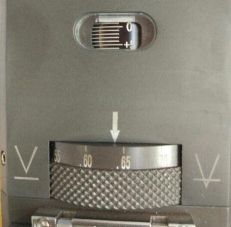
Figure 4-3 Focusing Device of Laser Head
The relation between focus position and cutting materials and sections is listed in the following table
| Name and location of focus | Cutting material and section features |
|---|---|
| Zero focus: laser focus is located on the upper surface of the sheet metal | It is used in sheet cutting. The upper cutting surface is smooth and lower surface is not smooth. |
| Positive focus: laser focus is located on the upper surface of the sheet metal | Operation method of the carbon steel plate. The focus is on the surface, thus the smooth surface range is quite large, the kerf is wider than the kerf of zero focal length, the gas flow is quite large in cutting and the perforation time is longer than that of zero focus. |
| Negative focus: laser focus is located below the upper surface of the sheet metal | Application of stainless steel, copper plate and aluminium plate. HP nitrogen is used to cutting the stainless steel to facilitate the molten slag protection section, and the kerf will be widened with the work piece thickening. |
Calibration
Place the sheet metal on the cutting table and position the cutting head above the sheet metal using the software and handle operation. In the CNC tab, click the BCS100 icon, then click [F1] CALIBRATE in the dialog box, and then click [2] CAPACITANCE CALIBRATION as shown in Figure 4-4. Use the down arrow to move the laser head to a position approximately 5mm-10mm above the sheet metal and click Enter as shown in Figure 4-5. After completing the calibration (when stability and smoothness are rated as Good), click the “Store” button and close the BCS100 interface. Click “Follow” to test if the follow function is working normally.

Figure 4-4 Initial Calibration Interface

Figure 4-5 Calibration Interface
It is suggested to conduct a calibration operation after each start-up and sheet metal replacement.
Cutting process
Drawing or importing the graphic data
Cyp Cut is equipped with user-friendly drawing functions and requires that the operator have drawing skills. These skills will not be further explained.
In addition to its built-in functions, the software can import files in formats such as DXF, AI, and PLT, as shown in the following figure.

Figure 4-6 Graphics Importing
Checking the graphics
After drawing and importing the graphics, it is important to check for errors or any unnecessary graphics.
The Draw tab (Figure 4-7) offers functions such as consolidating and connecting lines, removing repeated lines, and removing small graphics. If the graphics are complex, it is recommended to use these functions.

Figure 4-7 Checking Whether the Graphics Are Correct
Sometimes, the graphics imported may have size errors, thus it is also to check whether its size is wrong, if any, please correct it.

Figure 4-8 Checking Graphics Size
Setting process parameters
- Setting lead-in and lead-out lines
It is recommended to only set the lead-in line. If you are not satisfied with the automatically set lead-in line, you can change its direction by clicking “Outer” or “Inner” after selecting the closed line. To change the cutting start point, click “Lead Pos” and select the desired position. To change the processing direction, click “Reverse”

Figure 4-9 Lead-in Line Setting
- Sorting
When the graphics are complex, it is recommended to click the “O” icon after selecting an ordering rule and then sort the graphics. To simulate the cutting route in the software, click “Simu”. If the route procedures are not correct, please change the sorting rules.

Figure 4-10 Sorting Method
- Setting cutting parameters
Click “Layer” and set the appropriate cutting parameters in the pop-up dialog box. The machine has several sets of cutting parameters saved by the company during shipping, click “Load” and choose a suitable option to recall the parameters. Keep in mind that the recalled parameters are only for reference, and it is recommended for the operator to test and determine the most appropriate parameters based on actual conditions.

Figure 4-11 Parameter Setting Interface
- Focal length adjustment
Adjust the focal length based on material thickness, as shown in Section 4.2.4 and the following figure.
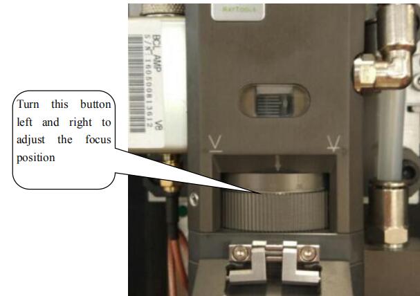
Figure 4-12 Setting Proper Focal Length
- Select the proper position and move it along the frame
Click “Home Ref” and choose the appropriate laser head stopping position. Move the laser cutting head to the correct position, click “Frame,” and verify that the test form is correct. Click “Dry cut” to run the machine without actually generating laser cutting. This step is optional and can be skipped to save time.

Figure 4-13 Setting Stop Position of Laser Head

Figure 4-14 Motion Control Panel
Notes: Before starting the processing, it is important to ensure that the workpiece’s dimensions fall within the limits of the sheet metal. This will prevent the laser cutting head from lowering outside the sheet metal and hitting the blade, which could result in damage to the laser during the cutting process.
- Cutting
Click “Follow” and “Puff” to test the normal functioning of the following and blowing, and then click “Start” to begin the cutting process once you have ensured safety.
Please be careful not to get burned when inspecting if the cut sample parts meet the requirements.
Notes:
Operating personnel can improve the quality of the workpiece and increase efficiency by finding the optimal parameters (such as velocity, air pressure, and focal length) through multiple tests.
It is recommended to save the determined parameters and include the focal length in the name for future reference when processing similar materials.
The operating software has powerful features, allowing capable personnel to conduct self-exploration while ensuring safety, making their work more efficient.
Factors influencing cutting principles
- The distance from nozzle to work piece is as shown in Figure 4-15;
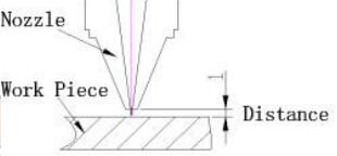
Figure 4-15 Distance Schematic Diagram of Nozzle and Work Piece
Too short distance will result in collision of sheet metal and nozzle, and too long distance will result in gas diffusion, causing many residues at the cutting bottom surface.
The distance from the nozzle to the workpiece can be set in ![]() layer interface, and distance between 0.5-1.5mm is recommended.
layer interface, and distance between 0.5-1.5mm is recommended.
- Cutting speed
The feeding speed can be determined by observing the cutting sparks. In normal cutting, the sparks will spread downward, and if the speed is too high, the sparks will be confined.
If the sparks appear to be concentrated rather than dispersed, it indicates that the feeding speed is too low.
As shown in Figure 4-16, a stable line will be produced on the cutting surface at an appropriate cutting speed, and no residue will be generated in the lower half.

Figure 4-16 Cutting Section Schematic and Cutting Spark Effect Diagram
Influence of too high speed on cutting quality:
- May give rise to cutting failure with sparks all around.
- Some areas can be cut off while others cannot.
- The cutting section is rough.
- Many residues. It is shown in Figure 4-17.

Figure 4-17 Cutting Effect Diagram
Influence of too low speed on cutting quality:
- May lead to over-melted sheet metal and rougher cutting fracture surface.
- The kerf will be wider to lower the cutting precision, and the small rounded corner or sharp corners may be melted.
- Low cutting efficiency influences production capacity.
- Gas and pressure
The type of assist gas used in laser cutting will vary depending on the material being cut.
The main functions of assist gas are to aid combustion, dissipate heat, blow away molten debris generated during cutting, prevent residue from entering the nozzle and damaging the focusing lens.
If the cutting pressure is insufficient, the cutting speed cannot be increased, which will affect production efficiency, result in more residue and degrade the quality of the cut.
If the assist gas pressure is too high, a wide kerf and rough cut will be produced on carbon steel sections. Additionally, the partial cut sections will become melted and the cutting quality will be affected.
If the gas pressure is too low during perforation, the laser will struggle to penetrate the sheet metal, causing a longer perforation time and reducing production rate.
A high gas pressure can cause sparks to fly, damage the protective lens, over-melt the breakthrough point and cause the hole to be too large, affecting the cutting quality.
In general, nitrogen is used to cut stainless steel and oxygen is used to cut carbon steel. The nitrogen pressure should be increased for thicker stainless steel and the oxygen pressure should be lowered for thicker carbon steel.
Therefore, the selection of assist gas and pressure setting for laser cutting should be adjusted based on the specific conditions, and other parameters should be adjusted to ensure optimal cutting results.
- Laser cutting power
The laser power also has an effect on the quality of laser cutting, and 100% of cutting power is used to ensure a rapid cutting speed and work efficiency.
Introduction to the remote control handle
For more convenient machine control, the remote control handle is supported as shown in Figure 4-18, the key functions will be introduced one by one as follows.
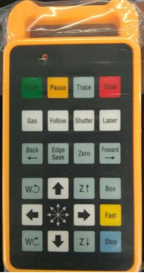
Figure 4-18 Remote Control Handle
Start: Start to work.
Pause: In case the machine is working or dry running, this key can be used to pause the operation. Click Start to continue to operate the machine.
Trace: It is similar to the Dry cut button functions at the software interface to enable the machine to be dry running without laser generation cutting.
Stop: In case the machine is working or dry running, this key can be used to stop the operation. Click Start to continue to start the machine again.
Gas: It is similar to the puff button function in the software interface, used to test whether the air blowing is normal.
Follow: Please ensure there is metal material under the laser head, this key can be used to open the following function of the laser cutting head.
Shutter: It is similar to Shutter key functions in the software.
Laser: When setting proper power in the software interface, the key can be clicked for laser generation. It is mainly used for dimming.
Back: click the key to move back some distance after the machine stops. And then click Start, and the machine can continue to move backward from the position.
Edge Seek: refer to automatic tracing-edge. If the sheet metal is put at a tilt when cutting plate, the control system can calculate its offset angle to use the materials effectively; if the operation is in mistake, it may damage the laser cutting head, so it is recommended to operate after the correct setting in the software. First press the Fast key and then click Edge Seek when cutting pipe to seek the middle position of the pipe.
Zero: it is related to the “Home Ref” in the software interface, after setting the stop position of the laser cutting head, click the key to make the laser head return to the previous position in case the laser cutting head is moved (i.e. the stop position of laser cutting).
Forward: click the key to advance some distance after the machine stops. And then click Start, the machine can continue to move forward from the position.
Motion control area: control the side-to-side movement of the X axis, front and back movement of the Y axis, up and down movement of the laser cutting head and anticlockwise or clockwise rotation of the rotation axis.
Box: its function is the same as that of the Frame button in the software interface, and it shall operate one circle along the graphics frame to define the operating range.
Fast: first press the key and then click a certain key within the motion control area to make the axis move quickly. Its movement speed is the added speed when fast movement in the motion control area of the software interface, for example: ![]()
Step: first press the key and then click a certain key within the motion control area to make the axis move step by step. Its step-by-step distance is the added distance when step-by-step movement in the motion control area of the software interface, for example: ![]()
Notes:
During the equipment processing, operating personnel shall hold the operation handle in hand all the time, not put the handle aside so that the operating personnel can press the key of “pause” or “stop” in emergency situations and it can avoid unnecessary damage for operating personnel and equipment.
Chapter V Introduction to Pipe Processing
Rotation center record
Similar to sheet metal cutting, calibration is required for pipe cutting, however, after completing the calibration, the automatic tracing-edge operation shall be operated and it can be completed by clicking “Edge Seek” on the remote control handle.
After completing the automatic tracing-edge operation, click “Save Rotate Center” in the software to record the center position, as shown in Figure 5-1.
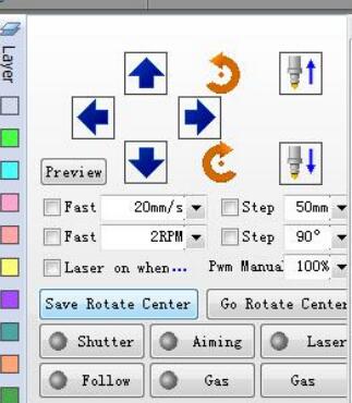
Figure 5-1 Rotation Center Record
Opening the graphics
Click OPEN to select the graph to be opened and Cyp tube supports 3D files in form of IGS. It shall select the proper tensile direction when opening the graph and select the outer wall contour line, as shown in Figure 5-2.

Figure 5-2 Select Proper Tensile Direction
Appropriate stop position selection
Under the tab of Home, click Home ref and select a proper stop position in the dialog box and it is recommended to select the farthest or nearest end, as shown in Figure 5-3.

Figure 5-3 Appropriate Stop Position Selection
Other operations
Other operations are similar to these of the part of sheet metal processing and please refer to Section 4.4.
For the installation and commissioning, it is strongly suggested that the operating personnel can come to the factory for learning or ask for assistance to your factory from the customer service staff of our company.
Chapter VI Basic Control Operation and Programming of RC Robot
Teach pendant
Keys of teach pendant

Figure 6-1 Switch of Teach Pendant
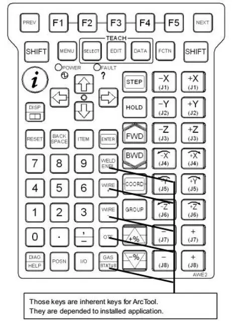
Figure 6-2 Key Switch of Teach Pendant
F1, F2, F3, F4, F5: Function key is used to select the function key menu in the last line of image.
NEXT: Page key is used to switch the function key menu to the next page.
MENU: Menu key is used to display the image menu.
FCTN: Auxiliary key is used to display the auxiliary menus.
SELECT: Overview key is used to display the overview image of the program.
EDIT: Edit key is used to display the edit image of the program.
DATA: Data key is used to display the data image.
TOOL: TOOL1 and TOOL2 keys are used to display the images of tool 1 and tool 2.
SET UP: Setting key is used to display the setting image.
STATUS: Status display key is used to display the status image.
I/O: Input/output is used to display the I/O image.
POSN: Position display key is used to display the current position of the image.
DISP: Move the image of operation object.
DIAG/HELP: Move to the prompt image when pressing alone. Move to the alarm image when pressing with SHIFT.
COORD: Types of manual coordinate system switching, following switches can be operated in turn: joint, manual, world, tool, user, joint.
FWD/BWD: It can start the program when pressing with SHIFT at the same time (forward/backward).
HOLD: It is used to interrupt the execution of program.
STEP: It is used to test the switching of intermittent operation and continuous operation in the process of operation.
PREV: Return key is used to display the status of returning to the tightening state.
It will not return to the status display of the previous tightening state under some conditions as per the operation.
BACKSPACE: Cancel key is used to delete a character or digital before the cursor position.
State display of teach pendant

Figure 6-3 State display of Teach Pendant
Processing: it represents that the robot is doing a certain operation.
Single section: it represents that it is in the operation mode of single operation. Pause: it represents that the HOLD key is pressed or HOLD signal is input. Abnormal: it represents there is an abnormal condition.
Implementation: it represents that the program is in implementation state. I/0: it is the inherent LED of the application program.
Running: it is the inherent LED of the application program.
Test run: it is the inherent LED of the application program.
Program composition
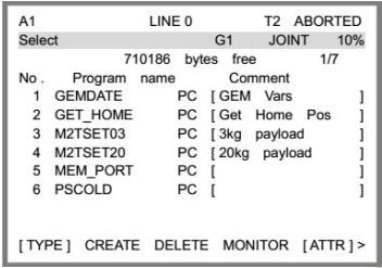
Figure 6-4 Overview Image of Program

Figure 6-5 Program Editing Screen
Program name
Different programs are distinguished based on different program names, which are as long as 1-8 bytes and must be unique.
Numbers, English capital and lowercase letters as well as underlines can be used as program names, while such symbols as @, ¥, % and # are not supported.
Programs must be named in a way that can indicate the purposes and functions of the programs.
The program of fixed fire laser may, for example, be named “DIANSHE” (the Chinese phonetic alphabets of “fixed fire”), so the general function of this program can be known rapidly in the future process of use.
The names below may not be used as program names:
COM1, COM2, COM3, COM4…… CON,PRN,AUX,NUL ……
LPT1, LPT2, LPT3……
Programs adopted with RSR must be named in the form of “RSRnnnn”, where “nnnn” refers to 4 digits, such as RSR0001. Otherwise, the program will not perform.
Type of actions
The robot can perform 4 types of actions: 1. J joint action: a type of joint action that excludes trajectory control or postural control. 2. L linear action: a type of linear action that includes rotary movement and performs trajectory control or postural control. 3. C circular action. 4. A C circular action.
Joint action J
Action is the basic move method to move the robot to a specified location.
The robot will accelerate along all the axes at the same time, move at the teaching speed and then stop after deceleration.
The movement paths are usually nonlinear ones, the type of action will be recorded when the endpoint is taught, and the postures of the tool are uncontrolled in the movement.

Figure 6-6 Joint Action
1: J P[1] 100% FINE
2: J P[2] 70% FINE
Linear action L
Linear action, as a kind of move method, means that the motion trail from the start point of action to the endpoint of the action is controlled in a linear mode, and the type of action will be recorded when the endpoint is taught.
The postures of the tool in the movement will be controlled after those at the start point and target point are divided.

Figure 6-7 Linear Action
1: J P[1] 100% FINE
2: L P[2] 500mm/sec FINE
Circular action C
Circular action, as a kind of move method, means that the motion trail of the tool center point will be controlled in a circular mode from the start point of action to the endpoint through the pathway point.
It will provide teaching for the pathway point and target point in one instruction, and will control the postures of the tool in the movement after dividing the postures at the start point, pathway point and target point.

Figure 6-8 Circular Action
1:J P[1] 100% FINE
2:C P[2]
P[3] 500mm/sec FINE
C circular action A
Under the instruction of circular action, two positions, i.e., the pathway point and end point, need to be taught in one line, while under the instruction of C circular action, only one position needs to be taught in one line, and a circular action will be executed when the circular arcs created by 3 continuous C circular action instructions are linked.
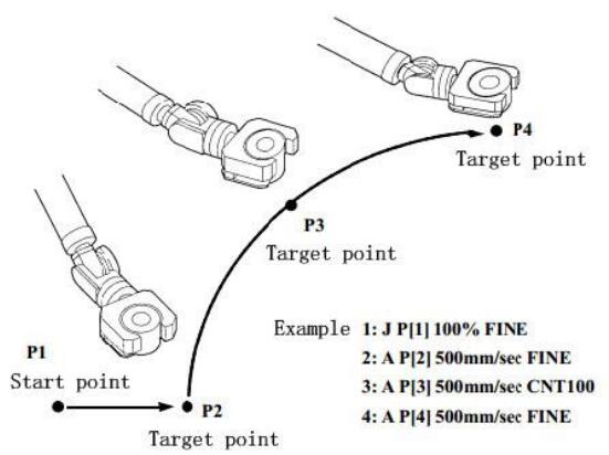
Figure 6-9 C Circular Action
1: J P[1] 100% FINE
2: A P[2] 500mm/sec FINE
3: A P[3] 500mm/sec CNT100
4: A P[4] 500mm/sec FINE
Program establishment
Program creation
Press SELECT, choose F2 “Create” and then a program record image will pop out.

Figure 6-10 Program Record Image
Click RSR and then enter a new file name, when “Up” and “Down” can be clicked to select to enter capital and lowercase letters. Press ENTER after the program name is entered.

Figure 6-11 Program Creation
Program execution
The program can be started in the following three methods: Press SHIFT+FWD/SHIFT+BWD on the TP
Press the start button on the operation panel
Peripheral equipment
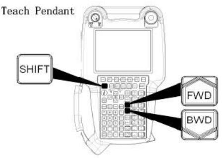
Figure 6-12 TP Operation for Program Start
Positioning type
FINE positioning type: According to FINE positioning type, the robot will stop (be positioned) at the target position before moving towards the next target position.
CNT positioning type: According to CNT positioning type, the robot will move close to the target position but won’t stop at it. Instead, it will act at the next target position.
The close degree of the robot to the target position will be defined by a number from 0 to 100.
In the case of 0, the robot will act in the position closest to the target position, but will not be positioned at the target position before starting the next action.
In the case of 100, the robot will not decelerate near the target position.
Instead, it will start actions towards the next point through the point that is the farthest away from the target position.
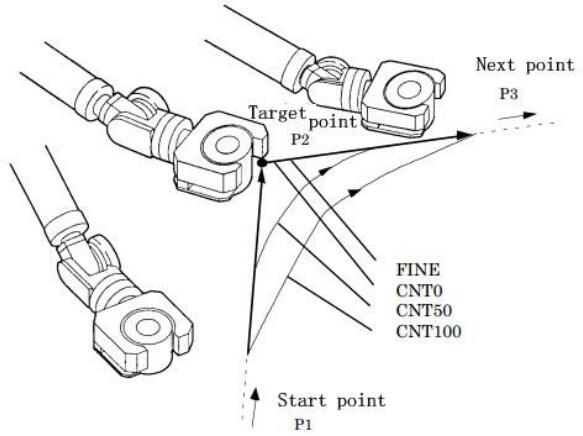
Figure 6-13 Comparison of Positioning Types
Chapter VII Operation Notes, Maintenance, Service and Troubleshooting
General notes
In the previous introduction, we have already highlighted the important points to be aware of. Please read carefully.
Below are additional points to consider:
- Operating personnel must strictly adhere to the safe operating rules of the laser cutting machine.
- Operating personnel should thoroughly review all the manuals supplied with the machine or receive training from our company’s customer service staff to become familiar with the equipment’s structure and performance and to master the operating system’s knowledge.
- Protective gear must be worn according to the rules, and protective eyeglasses that meet the standards must be worn in the vicinity of the laser beam.
- The material should not be processed until it is determined whether it can be subjected to laser radiation or heat to avoid the potential risk of smoke and steam.
- Once the machine starts operation, the operating personnel may not leave their post or ask others to operate it arbitrarily.
- Fire extinguishers should be readily accessible.
The laser and optical gate should be turned off when not in use.
Inflammable materials such as paper or cloth should not be placed near the laser beam without protection.
- If there is any abnormality during processing, it is necessary to shut down the machine and troubleshoot promptly or report to supervisors.
- Keep the laser, lathe bed, and surrounding area clean, organized, and free of grease, and stack workpieces, sheet metal, and waste according to the rules.
- When using gas cylinders, they should not be placed on wires, water pipes, or gas lines to prevent electric or water leaks or gas leaks.
Gas cylinders should be used and transported in accordance with gas cylinder regulations.
Gas cylinders should not be exposed to the sun or placed near heat sources.
To open the cylinder valve, the operating personnel must stand to the side of the cylinder opening.
- The water level of the water chiller should be checked when powered on, and it is strictly prohibited to power on the water chiller if there is no water or the water level is too low to protect the water cooling system from damage.
Squeezing or stepping on the water inlet and outlet pipeline of the water chiller is strictly prohibited to keep the water circuits smooth.
- The product produces a laser wavelength of 1064nm, which can cause skin burns and severe damage to the retina if exposed to laser radiation or watched for an extended period of time. Operating personnel must wear 1064nm protective eyeglasses.
- Cutting certain sheet metals can produce a lot of smoke, so the fan’s air duct should be vented outside or additional air cleaning units should be installed. Operating personnel should also wear dust masks to prevent occupational diseases.
- When the machine is not in use for a long time at a temperature below 0℃, the cooling water in the water chiller, laser, and water pipes should be drained to prevent damage to the equipment and pipelines from freezing at low temperatures.
- The protection lenses in the laser cutting head should be checked daily.
When dismantling the collimating lens or focus lens, the process should be recorded, and special attention should be paid to the lens’s installation direction, which should not be installed incorrectly.
Introduction to water chiller temperature settings
The water chillers produced by our company can automatically adjust the water temperature based on temperature and humidity and generally, no changes to the settings are required.
For laser sources with a power of 1000W or less, it is recommended to supply water for a certain period of time (approximately 10-20 minutes) before turning on the laser source. This has the following benefits:
If the temperature is low, the water temperature can increase as it circulates, which is beneficial for the normal operation of the laser source. If the humidity is high, the initial water supply may condense inside the machine, but the water chiller will automatically adjust to the proper water temperature after circulating for a certain period of time, eliminating the condensation.
Laser sources with a power greater than 1000W have built-in dehumidification devices that reduce humidity inside the laser source and lower the dew point.
Manufacturers of all laser sources require that the laser source be turned on first, and water should be supplied after the dehumidification device has operated for a period of time.
According to tests of various water chillers currently in use, in automatic temperature control conditions, the water temperature of low-temperature water is about 5℃ higher than the dew point, while that of high-temperature water is about 10℃ higher than the dew point.
If your water chiller is not configured with the standard configuration of our company or you need to set the water temperature yourself for special reasons, we recommend setting the water temperature of low-temperature water to be about 5℃ higher than the dew point, and that of high-temperature water to be about 10℃ higher than the dew point.
What is the dew point and how is it related to temperature and humidity?
Dew formation refers to the phenomenon of condensation on the surface of an object when the surface temperature of the object is lower than the surrounding air temperature.
(For example, there is dew on the outside of a beverage bottle taken from the refrigerator, which is an example of dew formation. If dew formation occurs inside the laser source or at the fiber pigtail, it can cause irreparable damage.)
The dew point is the temperature at which dew begins to form and is related to both temperature and humidity. The relationship is shown in the table on the next page.
For example, if the temperature is 25℃ and the humidity is 50%, the dew point would be 14℃ according to the table. This means that in an environment with a temperature of 25℃ and a humidity of 50%, the water temperature of the water chiller should be above 14℃ to prevent dew formation on the equipment being cooled.
In this case, we recommend setting the water temperature of low-temperature water to 19℃ and that of high-temperature water to 24℃ if you need to set them yourself.
However, the dew point can change easily, and dew can form if there is carelessness in setting the water temperature, so it is recommended to use the water chiller in automatic temperature control mode, that is, do not change any settings on the water chiller.
The best conditions for the machine to operate are in an environment with constant temperature and humidity.
If the environment where the equipment is located has a temperature below 0℃, it is recommended to run the water chiller continuously.
Otherwise, the water in the water chiller, laser source, laser cutting head, and pipeline should be completely drained after the equipment is turned off to protect the components from damage due to freezing.
The water chiller and laser source can be equipped with temperature control devices, while the water in the laser cutting head and pipeline, which are difficult to equip with temperature control devices, should be drained.
Comparison Table of Ambient Temperature, Relative Humidity and Dew Point
| Relative humidity Ψ (%) | 95 | 90 | 85 | 80 | 75 | 70 | 65 | 60 | 55 | 50 | 45 | 40 | 35 | 30 |
|---|---|---|---|---|---|---|---|---|---|---|---|---|---|---|
| Ambient temperature Ta (℃) | Dew point Td (℃) | |||||||||||||
| 10 | 9.2 | 8.4 | 7.6 | 6.7 | 5.8 | 4.8 | 3.6 | 2.5 | 1.5 | 0 | -1.3 | -0.3 | -5 | -7 |
| 11 | 10.2 | 9.4 | 8.6 | 7.7 | 6.7 | 5.8 | 4.8 | 3.5 | 2.5 | 1 | -0.5 | -2 | -4 | -6.5 |
| 12 | 11.2 | 10.9 | 9.5 | 8.7 | 7.7 | 6.7 | 5.5 | 4.4 | 3.3 | 2 | 0.5 | -1 | -3 | -5 |
| 13 | 12.2 | 11.4 | 10.5 | 9.6 | 8.7 | 7.7 | 6.6 | 5.3 | 4.1 | 2.8 | 1.4 | -0.2 | -2 | -4.5 |
| 14 | 13.2 | 12.4 | 11.5 | 10.6 | 9.6 | 8.6 | 7.5 | 6.4 | 5.1 | 3.5 | 2.2 | 0.7 | -1 | -3.2 |
| 15 | 14.2 | 13.4 | 12.5 | 11.6 | 10.6 | 9.6 | 8.4 | 7.3 | 6 | 4.6 | 3.1 | 1.5 | -0.3 | -2.3 |
| 16 | 15.2 | 14.3 | 13.4 | 12.6 | 11.6 | 10.6 | 9.5 | 8.3 | 7 | 5.6 | 4 | 2.4 | 0.5 | -1.3 |
| 17 | 16.2 | 15.3 | 14.5 | 13.5 | 12.5 | 11.5 | 10.2 | 9.2 | 8 | 6.5 | 5 | 3.2 | 1.5 | -0.5 |
| 18 | 17.2 | 16.4 | 15.4 | 14.5 | 13.5 | 12.5 | 11.3 | 10.2 | 9 | 7.4 | 5.8 | 4 | 2.3 | 0.2 |
| 19 | 18.2 | 17.3 | 16.5 | 15.4 | 14.5 | 13.4 | 12.2 | 11 | 9.8 | 8.4 | 6.8 | 5 | 3.2 | 1 |
| 20 | 19.2 | 18.3 | 17.4 | 16.5 | 15.4 | 14.4 | 13.2 | 12 | 10.7 | 9.4 | 7.8 | 6 | 4 | 2 |
| 21 | 20.2 | 19.3 | 18.4 | 17.4 | 16.4 | 15.3 | 14.2 | 12.9 | 11.7 | 10.2 | 8.6 | 7 | 5 | 2.8 |
| 22 | 21.2 | 20.3 | 19.4 | 18.4 | 17.3 | 16.3 | 15.2 | 13.8 | 12.5 | 11 | 9.5 | 7.8 | 5.8 | 3.5 |
| 23 | 22.2 | 21.3 | 20.4 | 19.4 | 18.4 | 17.3 | 16.2 | 14.8 | 13.5 | 12 | 10.4 | 8.7 | 6.8 | 4.4 |
| 24 | 23.1 | 22.3 | 21.4 | 20.4 | 19.3 | 18.2 | 17 | 15.8 | 14.5 | 13 | 11.4 | 9.7 | 7.7 | 5.3 |
| 25 | 23.9 | 23.2 | 22.3 | 21.3 | 20.3 | 19.1 | 18 | 16.8 | 15.4 | 14 | 12.3 | 10.5 | 8.6 | 6.2 |
| 26 | 25.1 | 24.2 | 23.3 | 22.3 | 21.2 | 20.1 | 19 | 17.7 | 16.3 | 14.8 | 13.2 | 11.4 | 9.4 | 7 |
| 27 | 26.1 | 25.2 | 24.3 | 23.2 | 22.2 | 21.1 | 19.9 | 18.7 | 17.3 | 15.8 | 14 | 12.2 | 10.3 | 8 |
| 28 | 27.1 | 26.2 | 25.2 | 24.2 | 23.1 | 22 | 20.9 | 19.6 | 18.1 | 16.7 | 15 | 13.2 | 11.2 | 8.8 |
| 29 | 28.1 | 27.2 | 26.2 | 25.2 | 24.1 | 23 | 21.3 | 20.5 | 19.2 | 17.6 | 15.9 | 14 | 12 | 9.7 |
| 30 | 29.1 | 28.2 | 27.2 | 26.2 | 25.1 | 23.9 | 22.8 | 21.4 | 20 | 18.5 | 16.8 | 15 | 12.9 | 10.5 |
| 31 | 30.1 | 29.2 | 28.2 | 26.9 | 26 | 24.8 | 23.7 | 22.4 | 20.9 | 19.4 | 17.8 | 15.9 | 13.7 | 11.4 |
| 32 | 31.1 | 30.1 | 29.2 | 28.1 | 27 | 25.8 | 24.6 | 23.3 | 21.9 | 20.3 | 18.6 | 16.8 | 14.7 | 12.2 |
| 33 | 32.1 | 31.1 | 30.1 | 29 | 28 | 26.8 | 25.6 | 24.2 | 22.9 | 21.3 | 19.6 | 17.6 | 15.6 | 13 |
| 34 | 33.1 | 32.1 | 31.1 | 29.5 | 29 | 27.7 | 26.5 | 25.2 | 23.8 | 22.2 | 20.5 | 18.6 | 16.5 | 13.9 |
| 35 | 34.1 | 33.1 | 32.1 | 31 | 29.9 | 28.7 | 27.5 | 26.2 | 24.6 | 23.1 | 21.4 | 19.5 | 17.4 | 14.9 |
| 36 | 35.18 | 34.05 | 33.1 | 32 | 30.9 | 29.7 | 28.4 | 27 | 25.7 | 24 | 22.2 | 20.3 | 18.1 | 15.7 |
| 37 | 36.2 | 35.2 | 34.05 | 33 | 31.8 | 30.7 | 29.5 | 27.9 | 26.5 | 24.9 | 23.2 | 21.2 | 19.2 | 16.6 |
| 38 | 36.95 | 36 | 35.06 | 33.9 | 32.7 | 31.5 | 30.3 | 28.9 | 27.4 | 25.8 | 23.9 | 22 | 19.9 | 17.5 |
| 39 | 36.8 | 36.2 | 34.9 | 33.8 | 32.5 | 31.2 | 29.8 | 28.3 | 26.6 | 24.9 | 23 | 20.8 | 18.1 | |
| 40 | 36.8 | 35.8 | 34.7 | 33.5 | 32.1 | 30.7 | 29.2 | 27.6 | 25.8 | 23.8 | 21.6 | 19.2 | ||
Maintenance and service
To ensure the normal operation of the laser cutting machine, daily maintenance is required.
As the entire machine tool consists of extremely precise components, care must be taken during routine maintenance, and all procedures for operating and maintaining each part must be strictly followed.
Additionally, maintenance must be performed by designated personnel and rough handling is prohibited to prevent damage to the components.
General standards
Maintaining the quality of the machine tool requires using the most appropriate lubricant for professional lubrication to avoid operational issues and their consequences.
Before starting operation, the machine tool must be thoroughly lubricated according to the lubrication instructions.
If the machine tool has not been used for an extended period of time (such as during ocean shipping), the lubrication condition of the entire machine tool must be checked.
The oil filler and discharge outlet should not be opened beyond the scheduled time and must be kept clean.
Only cloth without fibers should be used to wipe the oil grooves and lubrication points. Waste wool, kerosene, or gasoline should not be used.
Instead, thin liquid-state (“jet lubricating oil”) main shaft lubricating oil should be used.
Synthetic lubricating oil should not be mixed with mineral oil or synthetic oil from other manufacturers, including synthetic oil with the same features from other manufacturers.
Waste oil should only be drained when the turbine is in a warm-up state.
Special attention should be paid to the safe disposal of waste oil.
Cleaning: The entire equipment should be thoroughly cleaned at specified intervals. Dirt can be scrubbed or removed using an industrial vacuum cleaner.
Safety notice: The machine tool should be turned off using the master switch during maintenance and safety requirements must be strictly followed to avoid accidents.
The following is a list of common maintenance spare parts that users should prepare:
- Acetone: 500ml bottle with 99.5% purity and less than 0.3% water.
- Pledget: 5 packages.
- Alcohol: 500ml with a purity of more than 99.5%.
- Lens paper: 5 books.
- Blowing balloon: 1.
- Dropper needle: 1 (for medical purposes).
- Organic glass: 200x300x20.
- Ink stone (red): 1 piece.
- Cotton swab: 2 packages.
- Multimeter: 1.
Routing maintenance and service of peripheral equipment
Please refer to the corresponding operating instructions for the routing maintenance of water chilling machine, laser source and other peripheral equipment, and the following is just a general description.
1) Maintenance and service of water chiller
The maintenance and service information for the water chiller has already been provided earlier and will not be repeated here. It is important to conduct routine maintenance on all types of water chillers according to the corresponding maintenance instructions. The following maintenance instructions for a specific water chiller can be used as a reference.
| Maintenance period | Content of maintenance | Goal of maintenance |
|---|---|---|
| Every day | 1. Check whether the temperature of water chilling machine is set normally (set temperature 20±1℃) | Ensure that the temperature of cooling water supplied for laser is normal |
| 2. Check whether the sealing of the water circuit of water chilling machine, water temperature and water pressure meet the requirements | Ensure the normal operation of equipment and prevent water leakage | |
| 3. Keep the working environment of water chilling machine dry, clean and draughty | Do good for the excellent operation of water chilling machine | |
| Every month | 1. The dirt on the surface of the water chilling machine shall be cleared with mild detergent or high quality soaps instead of benzene, acids, abrasive powder, steel brush or hot water | Keep the surface of the water chilling machine clean |
| 2. Check whether the condenser is blocked by dirt and clear the dirt on the condenser with compressed air or brush. | Ensure the normal operation of condenser | |
| 3. Clean the air filter net: 3.1 Open the panel of the unit that holds the air filter net, pull it up and draw it out. 3.2 The dust on the filter net can be cleared with vacuum cleaner, air gun and brush. The filter net shall be shaken to dry before reinstalled if it is moist after cleaning. 3.3 Cleaning period: once a fortnight. Please make cleaning occasionally in case of serious dirt. | Prevent poor heat dissipation from resulting in bad refrigeration and burning out the water pump and compressor | |
| 4. Check the water quality of the water tank and follow up | Only good water quality can ensure the normal operation of laser | |
| 5. Check whether there is water leakage phenomenon in the pipeline of the water chilling machine. | Ensure that the water chilling machine is free from water leakage phenomenon | |
| Every 3 months | 1. Check the electrical components (such as switches and connection terminals) and wipe them with cloth | Keep the surface of the electrical parts of the water chilling machine clean in order to prolong the service life |
| 2. Replace the circulating water (distilled water) and wash the water tank and metal filter net. In case a ROFIN laser is equipped, the cooling water can be replaced every half year after corrosion inhibitor is added; in case a PRC laser is equipped, the cooling water can be replaced every half year after propylene glycol is added. | Ensure the normal operation of laser | |
| ★★★ Notes: The following are necessary to be done in case of stopping for a long time: a. Place the water chilling machine and water pipes in a place far away from dust. b. Pull the power line away from the socket and wipe it clean; c. Wash the body of the unit: Prevent water from being splashed on the electronic components when washing the inside of the unit; d. Drain all the water in the laser, cutting head and water chiller. | ||
2) Maintenance and service of laser and fiber pigtail
To keep your laser cutting machine working normally and producing high-quality cuts, it’s important to regularly check and maintain the laser source, which is the key equipment of the machine. The laser source requires minimal maintenance and the daily tasks include monitoring the cooling water and voltage for any abnormalities. If any issues are noticed, please contact the manufacturer for assistance.
Maintenance and service of lens
In order to keep the lower centering module of your laser cutting machine free from smoke and dust pollution, it is recommended to clean the protection lens once a day before starting work. To do this, completely loosen the screws of the protection lens drawer, carefully pull out the drawer using your thumb and forefinger while holding both sides of the drawer’s box and being careful not to lose the seal rings at the top and bottom of the drawer.
Then, cover the drawer’s mouth with gummed paper to protect the focus lens from dust. The protection lens is a flat mirror and the seal rings and lens can be removed by pressing on the lens. During installation, make sure to place the lens before pressing the seal rings back in place.
The collimating lens and focus lens are located inside the fiber cutting head, so if they need to be disassembled, make sure to record the disassembly sequence to ensure accurate reassembly.
(1) Guidelines for the Use of Lenses
To avoid scratches or corrosion, do not touch the optical surfaces of the focus lens, protection lens, and QBH head with your bare hands.
If there is any grease or dust on the lens surfaces, clean them immediately as it can seriously impact their performance.
Washing the optical lens surfaces with water or cleanser essence is strictly prohibited as the lens surfaces have a special membrane layer that can be damaged if washed.
Do not store the lenses in a damp place, as this can cause aging of the lens surfaces.
When installing or replacing the reflector, focus lens, or protection lens, do not apply excessive pressure as this can cause deformation and negatively impact the quality of the light beam.
(2) Procedures for Installing or Replacing Optical Lenses
Wear clean clothes, wash your hands with soap or cleanser, and wear light, thin, and clean white gloves before installing or replacing the lenses.
Do not touch the lenses with any part of your hand.
Hold the lenses from the side and avoid direct contact with the coating surfaces.
When assembling the lenses, do not blow on them with your mouth. Place the lenses on a clean table with several pieces of lens professional paper underneath to keep them steady.
Handle the lenses carefully to avoid bruising or dropping them and do not apply force to the coating surfaces.
Ensure that the bases where the lenses are installed are clean and clear of dust and dirt by using a clean air gun.
When installing the lenses into the bases, avoid applying excessive force to prevent deformation and negatively impacting the quality of the light beam.
(3) Lens Cleaning Steps
The cleaning method varies depending on the lens.
For lenses with a flat surface and no base, use lens paper to clean them. For lenses with a curved surface or base, use a cotton swab. The steps are as follows:
To clean a lens with lens paper: first, blow off any dust on the surface of the lens with a clean air gun. Then, clean the surface with alcohol or lens paper. When using lens paper, make sure to place the bright, clean side of the paper on the lens surface, add 2-3 drops of high-purity alcohol or acetone, and draw the lens paper out horizontally towards the operator. Repeat this process several times until the lens surface is clean. Do not apply pressure to the lens paper to avoid scratches. If the lens surface is very dirty, fold the lens paper 2-3 times and repeat the process until the lens surface is clean. It is forbidden to drag dry lens paper on the lens surface.
To clean a lens with a cotton swab: first, blow off any dust on the surface with an air gun, then remove the dirt with a clean cotton swab. Use a new cotton swab soaked in high-purity alcohol or acetone to wash the lens by making circular motions from the center of the lens to the circumference. Replace the cotton swab with a clean one when the circumference has been washed. Repeat this process until the lens is clean.
Observe the washed lens to ensure that there is no dirt or spots on its surface. Install the washed lens into the base according to the method described above.
Do not use second-hand cotton swabs for this process. If chips are difficult to remove on the lens surface, blow the surface with a rubber air blower. Clean both sides and check again to ensure that there are no residuals such as detergent, pledget, foreign matter, or impurities.
The lens must not be exposed to air after cleaning. It should be installed immediately or stored temporarily in a clean, sealed container.
(4) Storage of Optical Lens
Proper storage of the optical lenses can maintain their good quality. The storage environment temperature should be between 10-30℃ and lenses should not be stored in a freezing chamber or similar environment, as this can cause condensation and frost which can easily damage the lens. The temperature of the storage environment should not exceed 30℃, as this can impact the coating film on the lens surface.
The lens should be stored in a box in a non-vibrating environment, as vibration can easily deform the lens and affect its performance.
(5) Replacement of Quick-Wear Components
The nozzle located at the bottom of the cutting head is susceptible to breakdown due to harsh service conditions, and can be unscrewed to be replaced with a new one. After replacement, it is necessary to screw it back on and perform another capacitance calibration.
If a new ceramic body assembly is being replaced, the two gauge piles must be aligned with the locating holes of the inductive seat, the ceramic body should be laid flat and upright before tightening the clamping rings, and the nozzle should be screwed when the ceramic body is compressed.
Failing to meet these installation requirements may damage the parts of the inductive seat module and hinder normal system operation.
Maintenance and service when long-term parking
In case the machine tool is not to be used for an extended period of time, it is recommended to apply grease to all moving components of the machine tool and wrap them with anti-corrosion paper.
Check regularly for rust formation on other parts and perform rust removal and rust-proofing treatment as needed. Dust-proof covers can also be added to prevent rust formation.
For the lubrication of the gear rack, clean it with an antirust agent such as WD-40 and then evenly lubricate it with a hand spray grease such as Dinosaur 192.
To lubricate the linear slide rail, use a grease gun (such as R-301) to inject lithium base grease (such as MP-3) into the centralized lubrication seat. If the linear slide rail is not lubricated properly, the friction in the rolling parts will increase, leading to a reduction in lifespan.
The recommended lubricating grease for the linear slide rail and sprocket chain is lithium base grease, such as Jinguan Lithium Base Grease MP-3, which should be injected into the sliding block using a grease gun.
Note that the linear guideway is sealed with a dust-proof cover, so before injecting grease with a grease gun, the dust-proof cover’s bellow must be opened.
Analysis on and inspection of common problems
| Alarm position | Alarm name | Alarm reason and inspection method |
|---|---|---|
| Follower Alarm | Capacity diminish | 1. Nozzle is failed to be installed. |
| 2. Ceramic ring is loose | ||
| 3. There is something wrong with the connection | ||
| Capacity large | There is something wrong with the calibration, which shall be made again | |
| Servo alarm | 1. The servo of Z axis is not on | |
| 2. There is something wrong with the servo connection, and please check all the servo plugs. | ||
| Z+ Limit reached | Z+limit is triggered | |
| Z- Capacity large | Z-limit is triggered | |
| Communication timeout | 1. The network cable is not connected well | |
| 2. The IP of height-adjustment device is reset. | ||
| 3 The height-adjustment device is not on | ||
| Servo alarm | Alarm code: 910, 710, 720 | 1. The servo is not on |
| 2. There is something wrong with the servo connection, and please check all servo plugs. | ||
| Limit alarm | Y+ Limit | 1. The limit is triggered. |
| Y-Limit | 2. The limit is touched by something | |
| X+ Limit | 3. There is something wrong with the limit, which needs to be replaced | |
| X- Limit | 4. There is something wrong with the pinboard | |
| The cutting effects become worse suddenly. | 1. No calibration is made after material replacement | |
| 2. The nozzle is unclear or damaged | ||
| 3. The assisted gas pressure is insufficient | ||
| 4. The lens is polluted or damaged |
Annex: Cutting Speed Parameter List
After-sale warranty of Laser Machines
In order to guarantee the smooth processing of after-sales service, we will make the following announcements:
General principles
- Our company is responsible for maintaining facilities that fall within the warranty conditions.
- It is the responsibility of the user to maintain the integrity and independence of the machine during operation. Our company will not be held directly, indirectly, or jointly liable in the following situations:
- Using the equipment in an environment for which it was not designed
- Modifying the machine without authorization, including adding or removing parts or using parts from other brands
- Damaging the machine through improper operation or maintenance, not following the instructions provided
- Damage caused by movement or transportation.
Our company reserves the right to make changes to the product’s specifications and name without prior notice to the customer, as long as it does not impact the machine’s performance.
Please note that our company is only responsible for the quality and performance of the machine we sell, and we are not responsible for any indirect obligations or responsibilities.
Detailed Principles
Equipment Warranty: 3 Years
The equipment warranty is for 3 years, calculated from the production date indicated on the machine’s nameplate. The details of the warranty are as follows:
- Laser Module Warranty:
- Fiber module warranty: 2 years (3 years for 2KW and above).
- CO2 tubes:
- RF tube warranty: 1 year.
- Glass tube warranty:
- RECI tube: 10 months.
- 40W tube: 4 months.
Note: The laser module warranty is calculated from the production date indicated on the laser module tag.
- Exclusions from the Warranty:
Consumable parts, such as glass mirrors, belts, switches, gas nozzles, feet/wheels, keys/press boards, are not covered by the warranty.
- Peripheral Device Warranty (if applicable):
The warranty for peripheral devices is 1 year, calculated from the production date indicated on the device tag. These devices are maintained by the device manufacturers, with assistance from our company.
Peripheral devices include water chillers, fans, air pumps, water pumps, etc. (if the machine has them).
Accessories repair and shipping cost
Within the Warranty Period:
For free repair or replacement of accessories, the buyer must cover the shipping costs from their location to our company if testing, repair or replacement is necessary.
If the failure is found to be due to the quality of the parts after testing (excluding human factors and environmental conditions, etc.), it will be repaired or replaced free of charge and our company will cover the return shipping cost. If the failure is not caused by the quality of the parts, the buyer must pay for the repair fees and both-way shipping costs.
Note: Repaired parts must be returned to our factory. If the buyer owes spare parts, our company will void the machine’s warranty terms.
Outside the Warranty Period:
The buyer must pay for repairs and both-way shipping.
Door to Door Service Policies
We offer door-to-door services worldwide. The charging standards and service procedures are as follows:
(A) Charging Standards:
- Technician visa fees and domestic travel expenses, including transportation costs incurred during document processing;
- Training and maintenance fees: $200/day/person, based on the time of arrival and departure of the plane in the customer’s country;
- International round-trip tickets (to be reserved and paid for by the buyer, and the e-ticket information to be provided to our company);
- Accommodation abroad (to be arranged and paid for by the buyer).
(B) Overseas Training/Maintenance Procedures:
- Our company will calculate the fees listed in items 1 and 2 above and inform the buyer. After payment, we will arrange for the technician to apply for a visa.
- Once the visa is obtained, we will inform the buyer, who must provide the round-trip ticket information in item 3 and arrange accommodation in item 4.
- The buyer may only apply for an extension of training and maintenance with our company’s approval. The buyer must pay for the “extended training and maintenance service fees” prior to the start of the extended service.
Postscript
Our company reserves the right to interpret the manual and we will make every effort to ensure its accuracy. However, there may be errors or omissions in the manual due to the limited knowledge of the author. We will not be held responsible for any consequences resulting from these mistakes or omissions. Improper use of the manual or product may result in direct, indirect, special, incidental, or consequential damages or responsibilities, for which our company will not be held responsible. We welcome feedback and corrections from experienced users and peers.

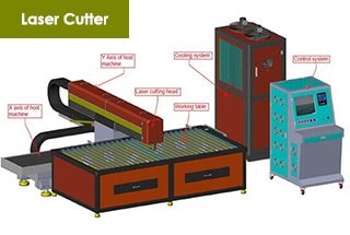
Sir, While visiting one industry producing nut,bolt,stud and many other fasteners of different grades steel bars En19, En8/D, 15B41 etc, rods were both hot and cold forged subsequently hardened at temp 850 deg C and tempered at temp 550-600 deg C and then threading done. Now the industry is anxious to know the technology and any machine available for cutting the rod while coming out from tempering temp of 300-350 deg C for mass production. Understand, laser cutting technology and machine available for sheet cutting. Shall be grateful if any indication given from your end so that industry can purchase both machine and technology of process. Getting idea, the industry will be referred for taking action. Regards – Srikumar Chakraborty , Metallurgical Consultant, Kolkata, India, email: [email protected]
Thank you very much,
Can I get this article as pdf ([email protected])
Sorry we don’t provide PDF file, anyway, you can read it here anytime.
Thanks for this, i appreciate this very much, sorry for my bad english, tomorrow i start a job with a laser cutter and works on this software, this is very useful for me, greetings from Argentina!
Glad to hear that and you’re welcome.
Hi can you please send to me parameters to lazer4k
My email … [email protected]
Do you have recomend parameter setting table for fiber 1500W? , such as nozle dimentor , speed , power. focuc in each tickness of material ( cabon steel , stainless steel , aluminum, )
You can refer to this post:http://www.machinemfg.com/laser-cutting-table/