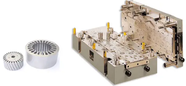
Blanking definition
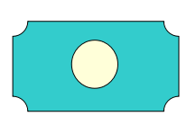
Blanking is a stamping process in which a mold is used to separate a portion of a sheet from another portion along a certain contour shape. In simpler terms, blanking involves using a mold to cut sheets apart.
Sign of the end of the blanking: the punch passes through the sheet into the die.
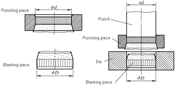
Main basic blanking process: blanking and piercing
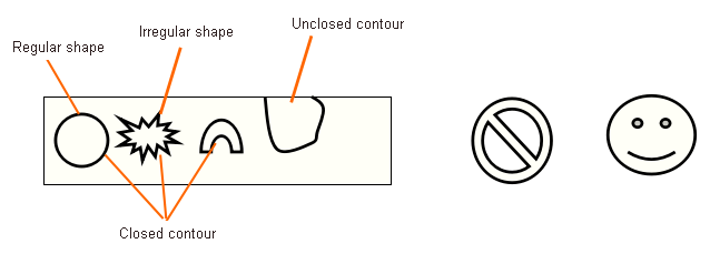
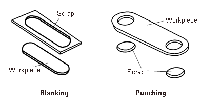
Both blanking and piercing utilize a mold to separate a portion of the sheet from another portion along a closed contour.
- The purpose of blanking is to get the part inside the closed contour
- The purpose of piercing is to get a part outside the closed contour
The mold for blanking is been called blanking die.
Blanking die features:
- There is a gap between the punch and die
- With sharp edge
Blanking classification
According to the different deformation mechanism of the blanking, the blanking can be divided into:
- Ordinary blanking
- Precision blanking
- Micro-blanking
In the following part we mainly focus on ordinary blanking.
Analysis of the blanking deformation process
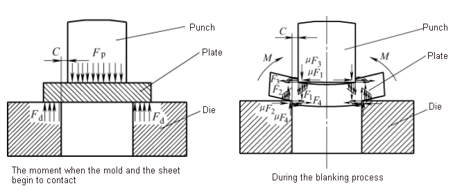
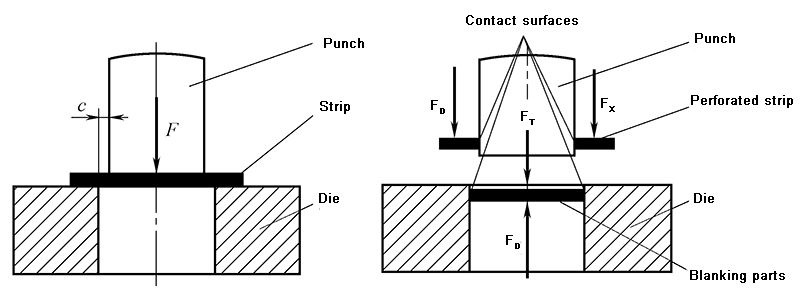
1.1 Analysis of the force on sheet metal in the blanking process
1.2 Blanking deformation process
When the mold gap is appropriate, the blanking deformation process can be divided into:
- Elastic deformation stage
- Plastic deformation stage
- Fragmentation separation stage
- Elastic deformation stage
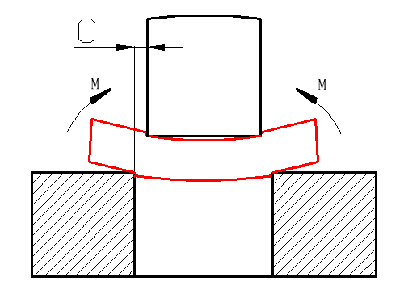
The initial stage of the punch just touching the sheet undergoes elastic deformation.
- Initial collapse angle (rounded corners)
- Material warpage
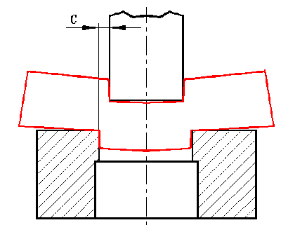
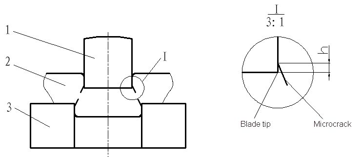
- Plastic deformation stage
- Larger sag angle
- Plastic shearing – bright band
- Internal stress reaches the limit
- Micro cracks appear near the edge
- Fragmentation separation stage
- Produce a rough and tapered fracture zone
- Burr formation
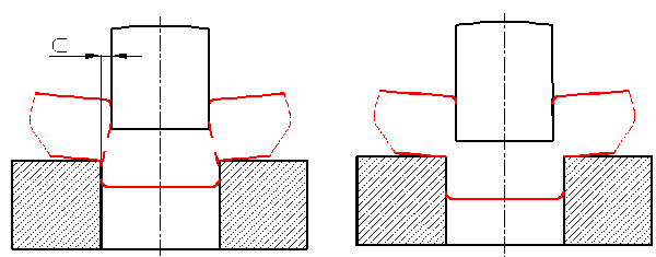
Important conclusion
(do not consider elastic springback)
- Blanking part size = die edge size
- Piercing part size = punch edge size
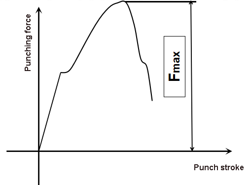
Change in the force of the blanking process:
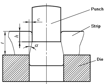
1.3 Blanking deformation zone position
The punched deformation zone is located in the spindle section of the upper and lower cutting edges.
Quality analysis and control of blanking parts
The quality of blanking parts refers to:
- Section quality: vertical, smooth, small burr
- Dimensional accuracy: Within the tolerances specified in the drawings
- Shape error: the shape meets the drawing requirements;
- The surface is straight, that is, the arch is small
2.1 Sectional features of blanking parts and their influencing factors
- Sectional features of the blank parts
Under normal clearance, the section of the blank part is composed of four parts:
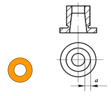
- Collapse zone a: The material near the edge produces bending and tensile deformation.
- Bright band b: plastic shear deformation. The area with the best quality.
- Fracture zone c: crack formation and expansion.
- Burr d: The gap exists, the crack is not generated at the edge of the blade, and the burr is inevitable.
The best quality part: bright band
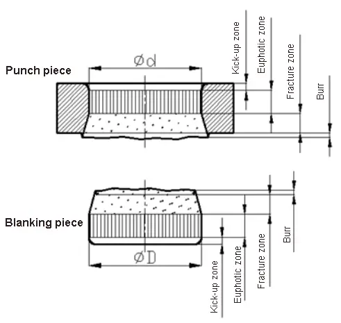
The position where the burr is generated: the crack is not on the tip of the blade, but is slightly above the punch and die sides.
- Factors affecting the section quality of the blanking parts:
(1) Influence of material properties
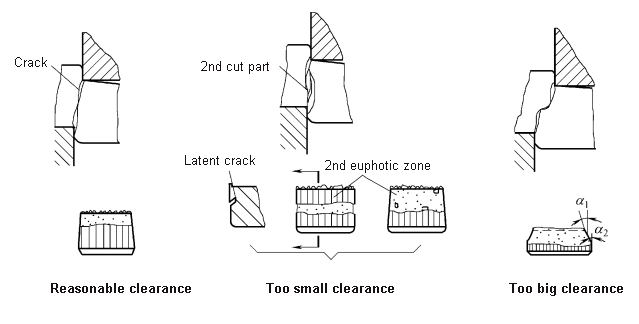
(2) Influence of mold gap
- The gap is suitable, the upper and lower cracks coincide, and the section quality is good.
- The gap is small and the section quality is good.
- The gap is too small, a secondary shear occurs, resulting in a second bright band
- The gap is too large and the quality of the section is degraded.
- The gap is too large and the section quality is the worst
Effect of clearance on shear crack and section quality.
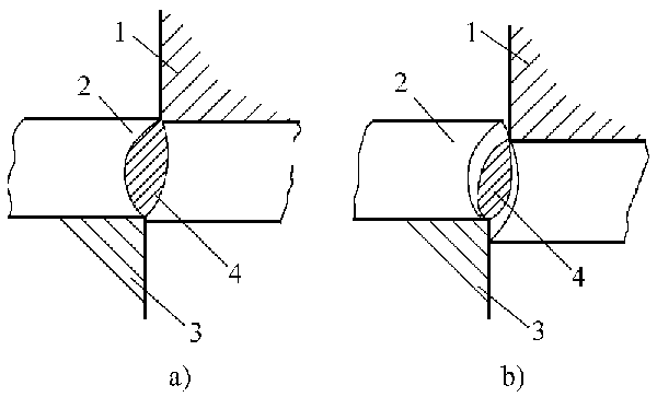
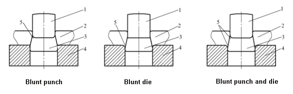
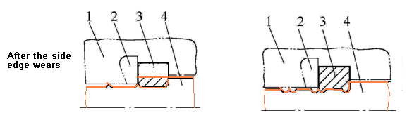
(3) Influence of mold edge state
- When the punch edge is blunt, burrs are generated at the upper end of the blanking parts;
- When the die edge is blunt, burrs are generated at the lower end of the hole of the piercing parts;
- When the punch and die edges are simultaneously blunt, burrs are generated on the upper and lower ends of the blanking parts.
2.2 Blanking size accuracy and its influencing factors
The dimensional accuracy of the blank is the difference between the actual size of the blank and the basic dimensions on the drawing.
The difference includes two deviations:
- One is the deviation of the blanking part from the size of the punch or the die;
- The second is the manufacturing deviation of the mold itself.
Influencing factors:
- Manufacturing precision of die (mold part processing and assembly)
- Material properties
- Blanking gap
2.3 Blank shape error and its influencing factors
Shape error of blanking parts: refers to defects such as warpage, distortion, and deformation.
Warpage refers to the unevenness of the blanked parts.
The deformation is caused by the extrusion due to the edge piercing of the blank or the hole distance is too small.
2.4 Blanking part quality control
- Control of dimensional deviation of working part of mold
- Die gap control
- Control of blanking material
- Control of other factors
Blanking process calculation
3.1 Layout design
1.Layout and material utilization
(1) Layout
Layout refers to the arrangement of the blanks on the sheets or strips.
Reasonable layout: improve material utilization, reduce costs, ensure the quality of stamping and improve the life of the mold.
(2) Material utilization rate
Material utilization is the percentage of the actual area of the part to the area of the material used.
Material utilization within one step:

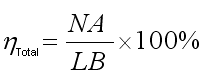
Total material utilization on a sheet (or strip, strip):
(3)Ways to improve material utilization
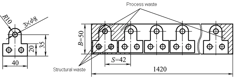
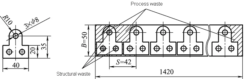
Type of waste:
- Structural waste: produced by the structural requirements of the workpiece, such as piercing waste
- Process waste: The waste that needs to be set up to complete the stamping process, including between the workpiece and the workpiece, between the workpiece and the side of the strip, the positioning hole, the material head, the tail, etc.
Measures to reduce process waste:
- Well-designed layout plan;
- Choose the right sheet size and reasonable cutting method (reduced material head, tail and edge);
- Use scrap as a small part.
Measures to utilize structural waste:
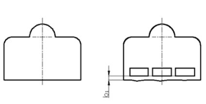
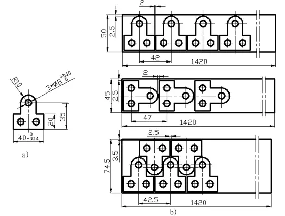
- When the material and thickness are the same, a smaller size blanking partcan be punched out of the larger size of the scrap as the size allows.
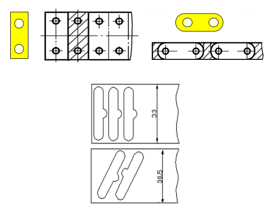
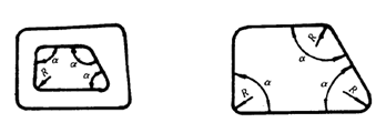
- Under the conditions of use, the structural shape of the part can also be changed to improve material utilization.
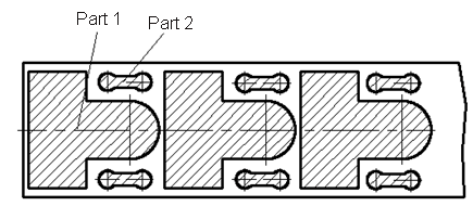
Change the shape of the structure to improve material utilization.
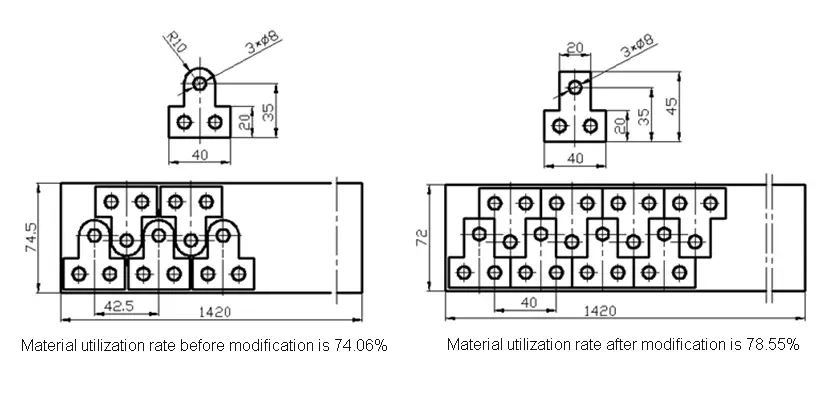
Which structure is more conducive to saving materials?
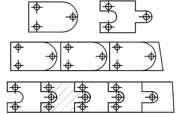
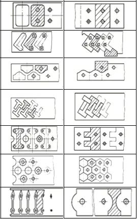
2.Layout type
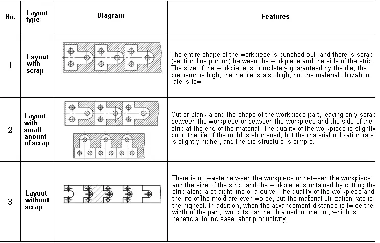
Layout form
Selection of layout:
- Shape of the part
- Part accuracy
- Material utilization
- Mold structure
- Die life
- Convenient and safe operation
- Determination of the lapping, the distance and the width of the material
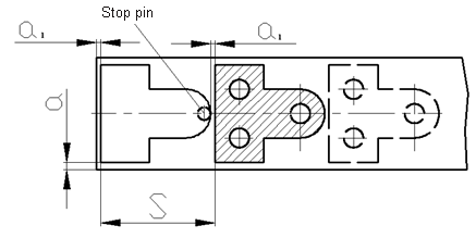
(1) Lapping and its role
Lapping: The process residue between the workpiece and the workpiece, and between the workpiece and the edge of the strip. There are the lapping a1 and the side lapping a.
Lapping function:
- Used for positioning;
- Compensate for positioning error and shear plate error to ensure that qualified parts are punched out;
- Increase the rigidity of the strip to facilitate the feeding of the strip and improve the labor productivity;
- Improve mold life.
Determination of the lapping value:
- Mechanical properties of the material: the lapping value of the hard material may be smaller; the lapping value of the soft material and the brittle material is larger.
- Material thickness: The thicker the material, the larger the lapping value.
- Shape and size of the blank: The more complex the shape of the part, the smaller the radius of the fillet and the larger the lapping value.
- Feeding and blocking method: manual feeding, the lapping value of the side pressure device can be smaller.
- Discharge method: The elastic discharge is smaller than the lapping of the rigid discharge.
- Determining the principle: take the minimum value on the premise of satisfying the effect, and the specific design information can be consulted.
Determination of the advance distance:
- The advance distance is also called the step distance, which refers to the distance that the strip advances on the mold every time the die is cut.
Determination of material width:
The determination of the strip width is related to how the strip is positioned in the mold:
- Guide plate and retaining pin positioning
- Guide plate with side pressure device
- There is no side pressure device in the guide plate
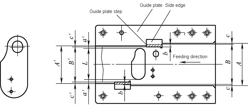
- Guide plate and side edge positioning
1)Determination of strip width with side pressure device
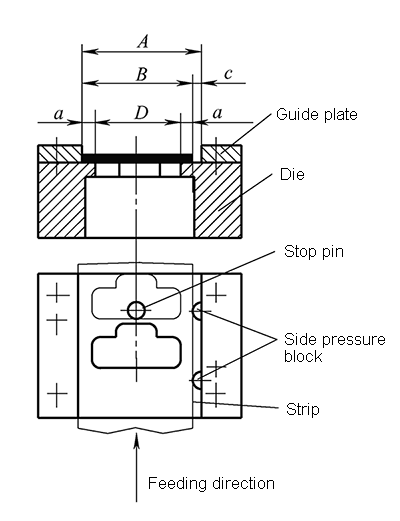
The strips are always fed on one side of the guide plate, so:

△—Cutting error
2)Determination of strip width without side pressure device
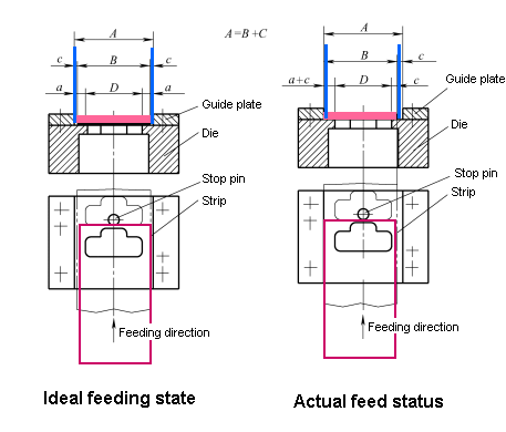

3)Determination of strip width when side edge positioning

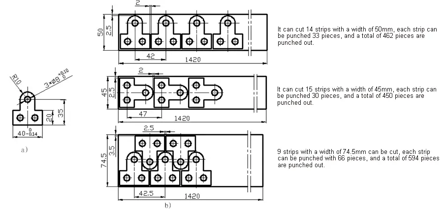
4)Cutting method
Can be cut vertically or horizontally.
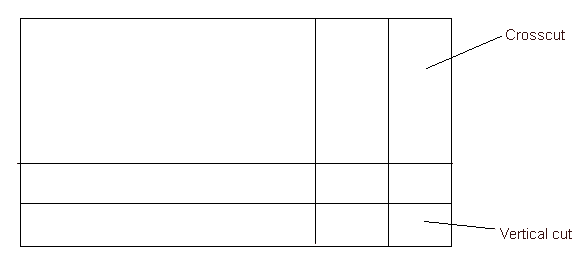
Calculate ηvertical and ηhorizontal respectively, and choose the larger ones after comparison.
In actual production, it is also necessary to consider production efficiency and ease of operation.
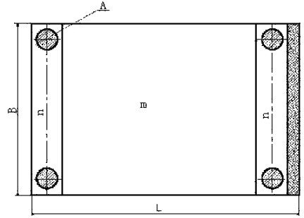
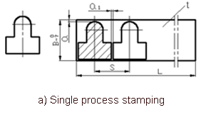
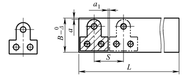
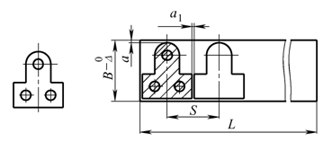
5)Drawing of the layout diagram
A complete layout should be marked with strip width dimensions, step distance S, laps between the workpieces, and side laps. The layout drawing is usually drawn in the upper right corner of the general assembly drawing.
- b) Compound stamping
Drawing requirements for mold assembly drawings
3.2 Calculation of blanking process force and pressure center
The blanking process strength mainly includes:
- Blanking force
- Unloading force
- Thrust force
- Ejecting force
1.Calculation of blanking force
Blanking force refers to the pressure required when blanking. This refers to the maximum value during blanking.
When punching with a common flat-blade die, the Blanking force F is generally calculated as follows:
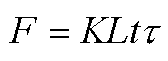
Note:
F ——Blanking force;
L ——Cutting length;
t ——Material thickness;
τ ——Material shear strength;
K ——Safety factor, generally take K = 1.3

2.Calculation of unloading force, thrust force and ejecting force
- Unloading force refers to the force required to unload the workpiece or waste material from the punch or die.
- Pushing force refers to the force required to push the workpiece or waste material in the blanking direction from the die.
- Ejecting force refers to the force that pushes the product out of the hole of the die by counter-punching the direction from the die.
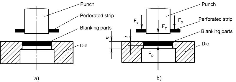
Calculation formula of unloading force, pushing force and ejecting force
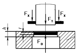
- Unloading force:FX=KXF
- Pushing force:FT=nKTF
- Ejecting force:FD=KDF
KX、KT、KD——Coefficient of unloading force, thrust force, ejecting force, see the table below;
| Material thickness t(mm) | KX | KT | KD | |
| Steel | ≤0.1 | 0.065~0.075 | 0.1 | 0.14 |
| >0.1~0.5 | 0.045~0.055 | 0.063 | 0.08 | |
| >0.5~2.5 | 0.04~0.05 | 0.055 | 0.06 | |
| >2.5~6.5 | 0.03~0.04 | 0.045 | 0.05 | |
| >6.5 | 0.02~0.03 | 0.025 | 0.03 | |
| Aluminum, aluminum alloy, copper, brass | 0.025~0.08
0.02~0.06 | 0.3~0.07
0.03~0.09 | ||
Note: The discharge force coefficient KX is taken as the upper limit when piercing holes, large overlaps and complex contours.
n——The number of blanking parts (or scraps) in the die edge at the same time.

In the formula:
F—一Blanking force(N)
h——Straight edge wall height of the die orifice
t——Sheet thickness
The punching force when blanking is the sum of blanking force, unloading force and ejecting force.
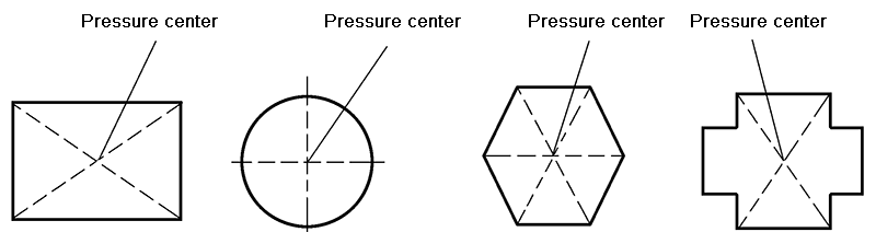
3.Calculation of pressure center
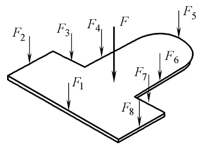
The center of pressure is the working point of the resultant force of the stamping.
The symmetrical center of the blanking part has its pressure center on the geometric center of the blanking profile.
The blanking pressure center of a complex-shaped workpiece or a multi-convex die blanking part can be analytically calculated according to the principle of moment balance.
Calculation of the pressure center of a complex blanking part with a single punch
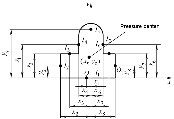
1) Draw the blanking contour of the blanking workpiece in proportion.
2) Establish a rectangular coordinate system xoy.
3) The blanking profile of the blanking part is decomposed into a number of straight line segments and circular arc segments L1, L2, L3 … Ln and other basic line segments.
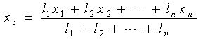
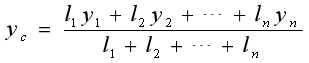
4) Calculate the length of each basic line segment and the distance y1, y2, y3 … yn and x1, x2, x3 … xn from the center of gravity to the coordinate axis x, y.
5) Calculate the coordinates xc and yc of the pressure center.
Calculation of pressure center in multi-press punching
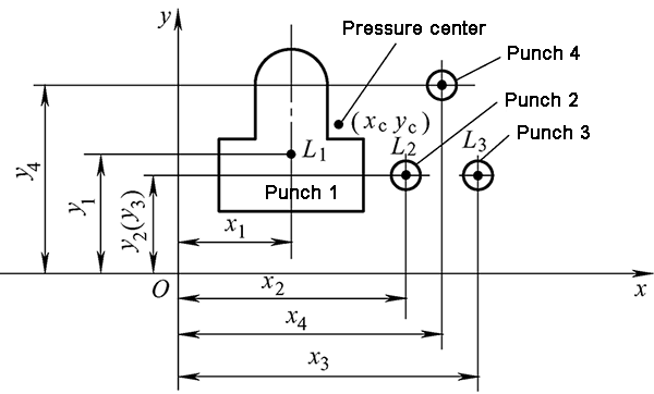


1) Draw the outline of each punch in proportion
2) Establish Cartesian coordinate system xoy
3) Find the coordinates of the gravity center of each convex die (xi, yi)
4) Calculate the punching length Li of each punch
5) Calculate the coordinates xc and yc of the pressure center
Blanking process design
4.1 Processability analysis of blanking parts
The technicality of the blanking part refers to the adaptability of the blanking part to the blanking process. It is a requirement from the perspective of product design.
Good punching process means that ordinary punching methods can be used to obtain qualified punching parts under the conditions of higher mold life and productivity and lower cost.
The craftability of the blanking part is determined by its structural shape, accuracy requirements, form and position tolerances, and technical requirements.
1.Structure technology of blanking parts
(1)The structure of the blanking part is as simple and symmetrical as possible, which is beneficial to the rational use of materials as much as possible.
(2)The shape and inner hole of the blanking part should avoid sharp corners and should have appropriate rounded corners.
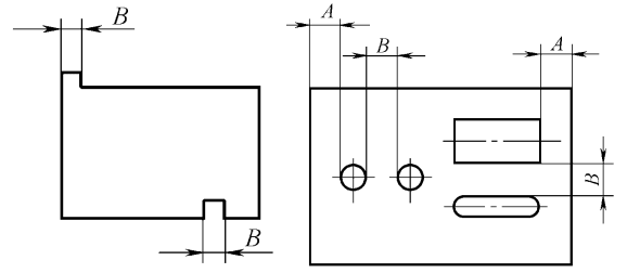
(3)Avoid long and narrow cantilever and groove on the blanking part. Generally, the width B of the convex and concave parts should be greater than or equal to 1.5 times the plate thickness t, that is, B≥1.5 t.
(4)Hole edge distance and hole spacing should be greater than or equal to 1.5 times the plate thickness t.
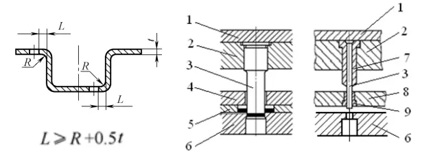
(5)When punching holes on curved or deep-drawn parts, a certain distance should be maintained between the edge of the hole and the straight wall.
(6)When piercing, the hole size should not be too small.
- Dimensional accuracy of blanking parts (GB / T13914-2002)
It is divided into 11 levels, which are represented by the symbol ST, and are gradually reduced from ST1 to ST11.
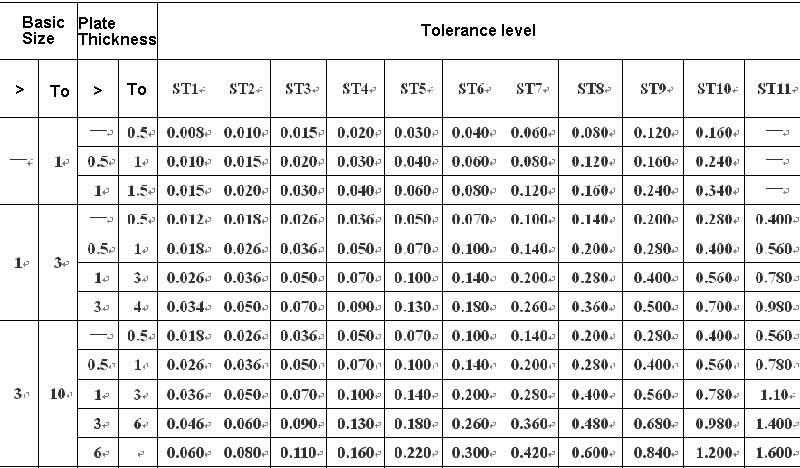
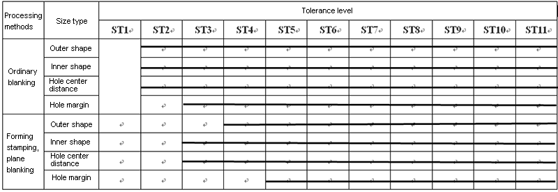
Table 3-12 Selection of tolerance grades for common blanking parts (GB / T13914-2002)
- Sectional roughness of blanking parts
| Material thickness t/mm | ≤1 | 1-2 | 2-3 | 3-4 | 4-5 |
| Surface roughness of blanking section Ra/μm | 3.2 | 6.3 | 12.5 | 25 | 50 |
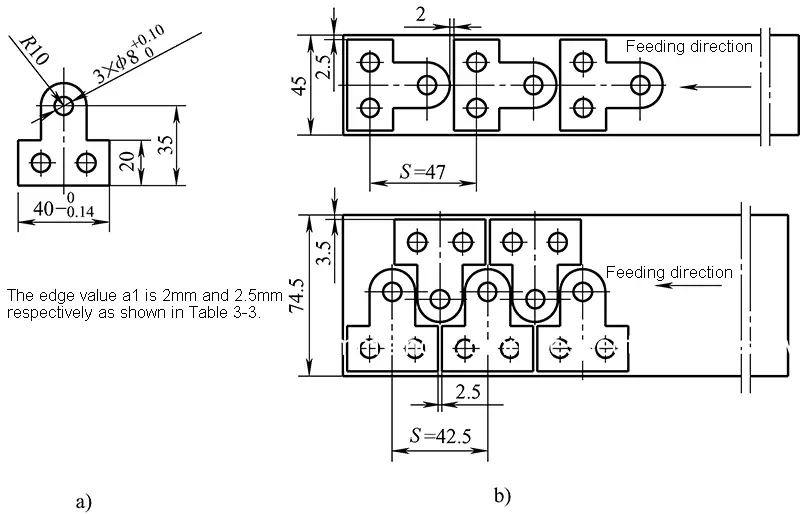
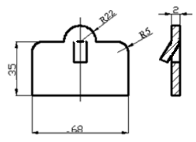
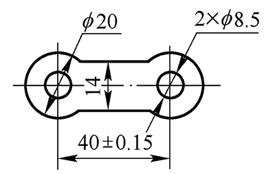
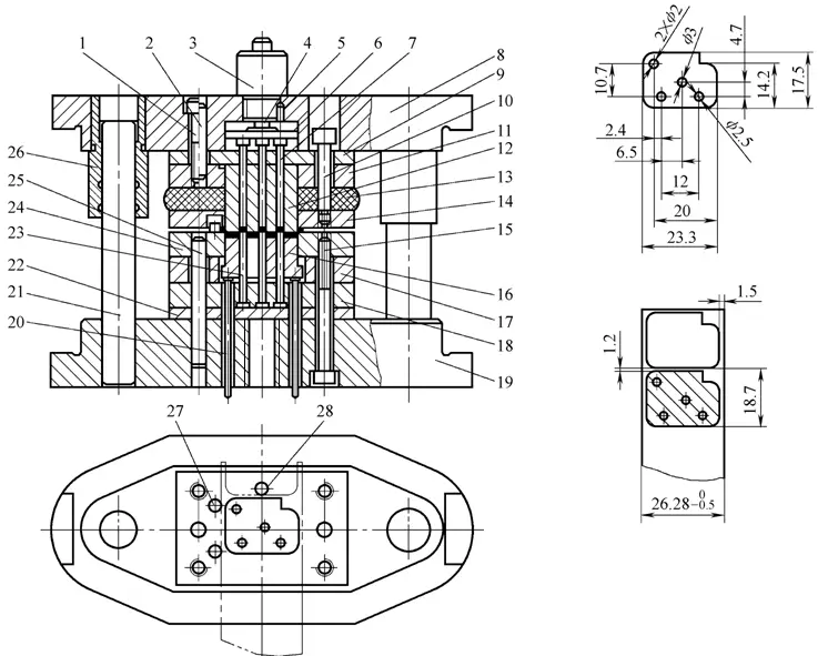
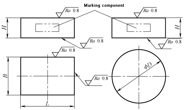
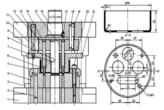
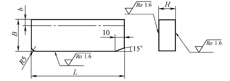
Example 3-3 The blanking part shown in the figure is made of material Q235 with a thickness of 2mm. Try to analyze the blanking processability.

Analysis:
(1) The blanking structure is symmetrical, without grooves, cantilevers, sharp corners, etc., which meets the blanking process requirements
(2) As can be seen from Table 3-11 and Table 3-12, the accuracy of the inner hole and the external dimensions and the accuracy of the hole center distance are all general accuracy requirements, which can be punched out by ordinary blanking.
(3) As can be seen from Figure 3-42 and Table 3-9, the size of the punched holes, the hole margins and the hole spacing dimensions all meet the minimum requirements, and composite punching can be used.
(4) Q235 is a commonly used stamping material and has good stamping processability.
In summary, the blanking part has good blanking processability and is suitable for punching.
4.2 Determination of process plan
Based on process analysis, comprehensive considerations from the aspects of structure, accuracy, size, batch, etc. need to be resolved:
- Basic stamping process
- Combination of basic stamping processes
- Arrangement of Blanking Order
- Determination of the number of basic processes
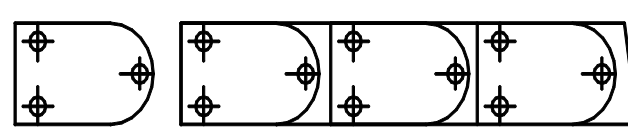
The number of basic processes required for a blanking part can be directly judged by its shape.
Example of determining the number of basic operations
- Combination of basic stamping processes
- Single process punching: Only one punching process can be completed in one stroke of the punch
- Composite punching: There is only one station, and in one stroke of the press, two or more stamping processes are completed at the same time.
- Progressive punching: In one stroke of the press, multiple stamping processes are completed simultaneously on multiple stations arranged in the feeding direction.
The corresponding dies are single-step punching die, compound punching die and progressive punching die.
Composite punching die
There is only one station, and in one stroke of the press, two or more punching processes are completed at the same time.
Progressive punching die
In one stroke of the press, the dies for multiple punching processes are completed simultaneously on a plurality of stations arranged continuously in the feeding direction.
Comparison of three types of molds
| Mold type | Single process mold | Compound mode | Progressive mold |
| Number of stations | 1 | 1 | 2 or more types |
| Number of completed operations | 1 type | 2 or more types | 2 or more types |
| Suitable blank size | Large and medium | Large, medium and small | Medium and small |
| Material requirements | The strip width is not strict, and the scrap can be used. | The strip width is not strict, and the scrap can be used. | Strict requirements for strips or strips |
| Punching precision | Low | High | Between the two |
| Productivity | Low | High | Very high |
| The possibility of mechanization and automation | Easier | Difficult, complicated workpiece and waste removal | Easy |
| Application | Suitable for medium and small batch production of large precision parts, large and medium-sized parts, or mass production of large parts | Suitable for mass production of large, medium and small parts with complex shapes and high precision requirements | Suitable for mass production of small and medium-sized parts with complex shapes and high precision requirements |
Is the process complex and how to choose it?
- Structure size
- Productivity
- Precision
- Easy and safe operation
- Production batch
- Mold cost
The general principles are:
- For mass production, composite or progressive stamping is used. For small batch production, single-process mold production should be used.
- Large size should use single process or composite mold
- Small size and high precision requirements, even if the batch is small, it should be produced by compound or progressive die
- Arrangement of blanking order
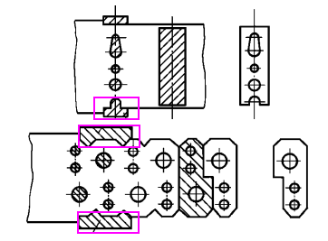
(1) Order arrangement of progressive punching
- First punch holes (notches or structural waste of the workpiece), and then blank or cut to separate the workpiece from the strip.
- When using fixed-range side blades, the side-edge cutting process is generally arranged first, and is performed simultaneously with the first punching to control the feeding distance. When two fixed-range side blades are used, they can also be arranged one behind the other.
(2) Sequence arrangement for single-step blanking of multi-step blanking parts:
- The blank is separated first to separate the blank from the strip, and then pierced or punched.
- When punching holes of different sizes and close distances, in order to reduce the deformation of the holes, punch the larger holes first and then the smaller holes.
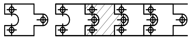
Example of sequence order for progressive stamping
- Basic steps for determining blanking process plan
- Analyze the blanking process of the product
- List the required basic stamping operations
- List possible options
- Analyze and compare to get the best solution
Examples of stamping scheme determination methods
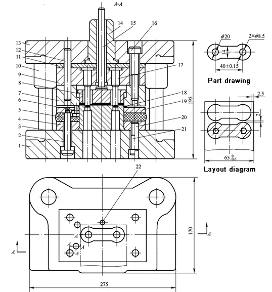
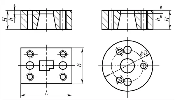
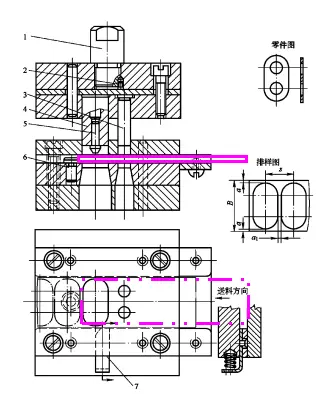
Example 3-4 Stamping illustrated parts, with an annual output of 3 million pieces, it is required to develop a stamping process plan.
(1) Analysis of stamping technology
1) The blanking structure is symmetrical, without grooves, cantilevers, sharp corners, etc., which meets the blanking process requirements.
2) As can be seen from Table 3-11 and Table 3-12, the accuracy of the inner hole and the external dimensions and the accuracy of the hole center distance belong to the general accuracy requirements, which can be punched out by ordinary punching.
3) As can be seen from Figure 3-42 and Table 3-9, the size of the punched holes, the edge distance and the hole pitch size meet the minimum requirements, and composite punching can be used.
4) Q235 is a commonly used stamping material and has good stamping processability.
In summary, the blanking part has good punching processability and is suitable for punching.
(2) Determine the stamping process plan
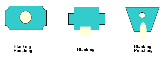
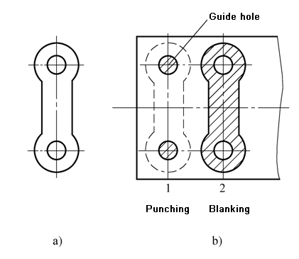
This part requires two basic blanking procedures, blanking and piercing. According to the above process analysis, the following three process solutions can be listed:
- Option 1: Use single process die production, that is, blanking first, then piercing
- Option 2: Production by composite die, that is, blanking-piercing at the same time
- Option 3: Use progressive die production, that is, continuous piercing and blanking
(3) Analysis and comparison
The first solution has a simple mold structure, but requires two processes and two pairs of molds, which has low productivity, and it is difficult to meet the efficiency requirements for mass production.
The second solution requires only one pair of molds. The shape and position accuracy and dimensional accuracy of the blanking part can be easily guaranteed. The productivity is higher than the first solution, but the mold structure is more complicated than the first solution and the operation is inconvenient.
Option three also requires a pair of molds, which is convenient and safe to operate and has the highest productivity. The mold structure is more complicated than option one. The precision of the punched parts is between option one and option two. However, because the accuracy of the product itself is not high, it can Meet the accuracy requirements of the product.
Through the analysis and comparison of the above three schemes, it is better to adopt scheme three for the stamping production of this part.
Overall structure design of blanking die
5.1 Classification of blanking dies
| No. | Classification basis | Name |
| 1 | Stamping process properties | Blanking die, bending die, deep drawing die, forming die, etc. |
| 2 | Different combinations of processes | Single process mold (simple mold), compound mold, progressive mold (continuous mold, skip mold) |
| 3 | Different orientation methods | No guide mold, guide plate mold, guide column mold, etc. |
| 4 | Different discharge methods | Rigid discharge die, elastic discharge die |
| 5 | Different ways to control the distance | Stopper pin type, side blade type, guide pin type, etc. |
| 6 | Materials for mold working parts are different. | Carbide mold, zinc-based alloy mold, rubber die, etc. |
| 7 | … | … |
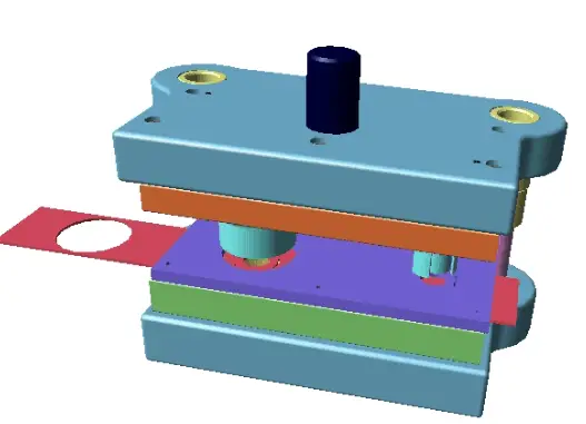
5.2 Typical structure of blanking die
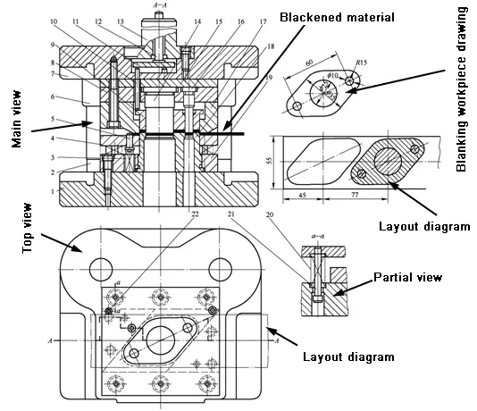
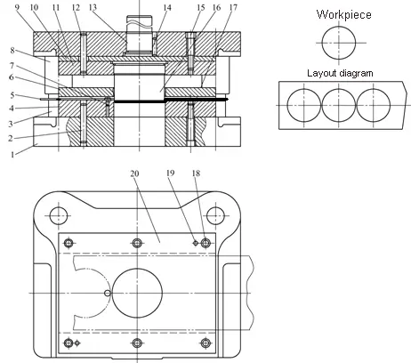
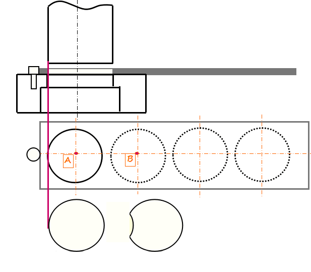
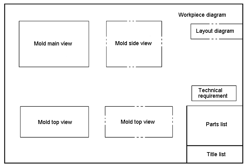
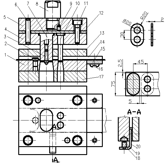
Viewing method of mold structure diagram
Viewing method and steps:
-Look at the title bar for mold names
-Look at the workpiece
-Look at the layout chart, understand the feeding direction, and then know the approximate location of the positioning part
-Look at the main view
- Find black materials and workpieces
- Find working parts that shape sheet metal
- Find positioning parts, combined with top view
- Find pieces
- Find guide parts
- Finding fixed parts
- Typical structure of single process mode
A single process die is also called a simple die, which refers to a die that completes only one stamping process in one stroke of the press.
Blanking die with rigid discharge device
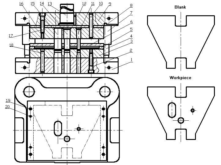
Blanking die with elastic discharge device
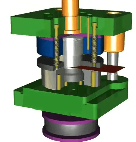
Single process blanking die with elastic discharging and ejecting device
Separation occurs
Piercing mold
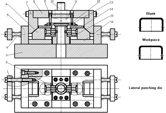
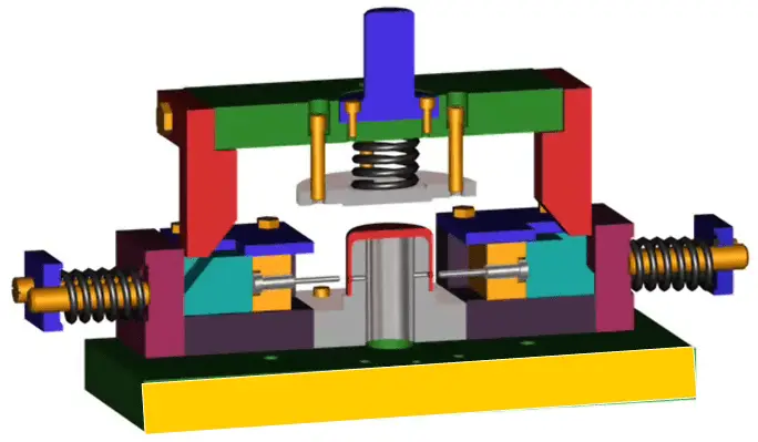
Oblique wedge type horizontal side piercing die
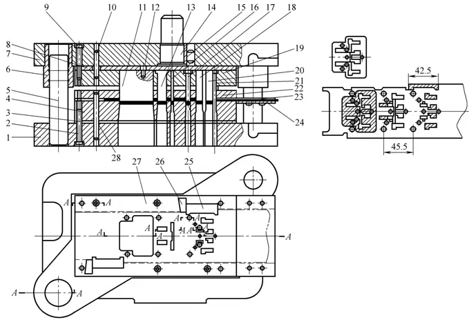
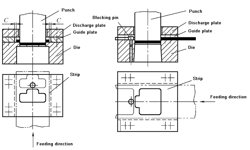
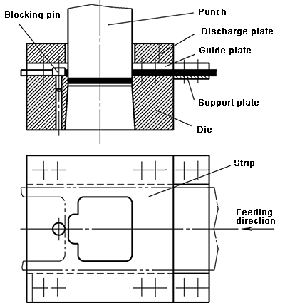
2.Typical structure of progressive die
Progressive die, also known as continuous die or skip die, refers to a die that simultaneously completes multiple stamping processes at multiple stations in the feed direction in a single stroke of the press.
Piercing and blanking progressive die
Punching and blanking progressive die with a fixed distance using guide pins

Piercing and blanking progressive die with double-side blade distance

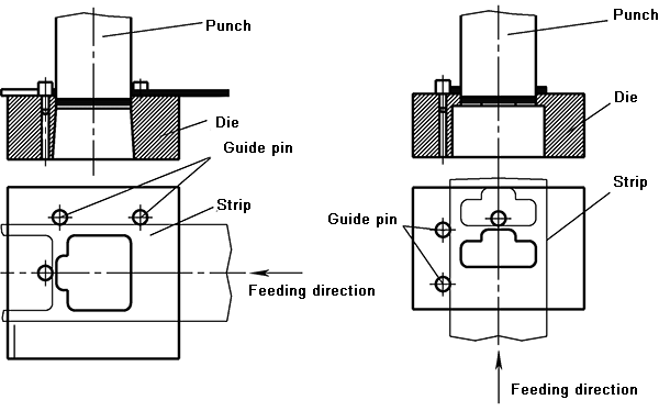
Progressive blanking die with side edge and guide pin joint distance
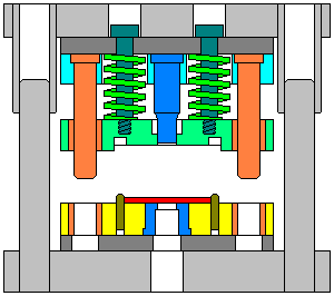
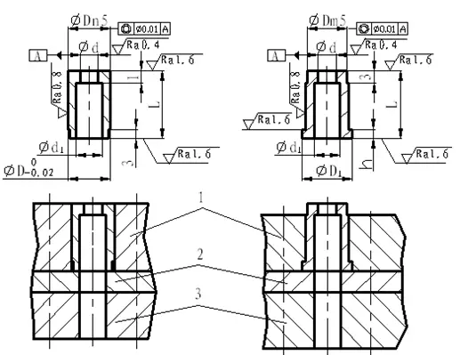
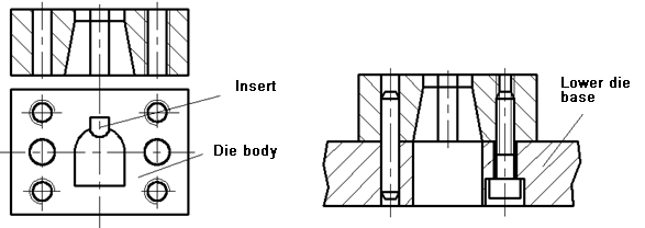
3.Typical structure of compound die
A compound die is a die that has only one station and completes two or more stamping processes at the same time in one stroke of the press.
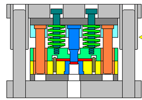
- Flip chip compound die
- Forming compound die
Comparison of forming and flip-chip compound dies
| Mold type / Features | Forming compound die | Flip-chip compound die |
| Blanking die position | Lower die | Upper mold |
| Workpiece flatness | With the action of pressing material, the flatness of the workpiece is good | Poor |
| Hole margin of the punchable workpiece | Smaller | Larger |
| Easy to operate and safe | Inconvenient to punch material | More convenient |
| Application range | Punching parts with materials in softer, thinner and higher flatness | Wide range of applications |
Forming compound die
Flip-chip compound die
Trimming and piercing compound die
Inverted composite die with rigid-elastic pusher device

5.3 Type selection of blanking die
For single-process molds, due to the convenience of the molds of the front-mounted structure, the front-mounted structure is preferred;
For composite molds, because of the convenience and safety of flip-chip composite molds, flip-chip structures are given priority in actual production. When the punched sheet is thin, the hole spacing is slightly smaller, and the flatness of the workpiece is required, the composite mold of the front-mounted structure should be selected.
In the mass production of small and medium-sized parts, progressive die with automatic feeding is widely used to save labor and improve production efficiency.
Design of main mold parts and selection of standards
Process structural parts:
- Work parts: male die, female die, male and female die, side blade
- Positioning parts: guide plate, blocking pin, guide pin, etc.
- Unloading and pusher parts: discharge board, pusher block, ejectingblock, scrap cutter
Auxiliary structure parts:
- Guide parts: guide post, guide sleeve, guide plate
- Fixed parts: fixing plate, backing plate, mold handle, upper mold base, lower mold base, screws, pins, etc.
6.1 Design of working parts and selection of standards
The function is to separate the materials and obtain the required shape and size of the blank
- Punch
- Die
- Convex and concave die
- Side edge
- Determination of die clearance
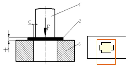
Blanking die clearance refers to the distance between the die and the side wall of the punch edge in the blanking die. It is represented by the symbol c, which refers to a single-sided gap. (GB / T16743-2010)

(1) Impact of clearance on the blanking process
1) The influence of clearance C on the quality of the part. The clearance value can be appropriately reduced, which can effectively improve the section quality of the blanking part.
2) Influence of clearance C on punching process force
As C increases, the punching force F is reduced to a certain extent.
As C increases, FX, FT, and FE decrease, the total punching pressure decreases.
Conversely, when Z is reduced, each blanking process force will increase, and the total punching pressure will increase.
3) Influence of clearance C on mold life
Forms of mold failure: wear, die edge cracking, chipping, deformation, etc.
The gap C mainly affects the wear of the mold and the edge crack.
When C is increased, because the blanking process force is reduced, the die wear is reduced, and the die edge cracks are reduced, so the life is increased. On the contrary, the life is shortened.

Analysis results:
- Improved part quality requires less die clearance
- Reduced punch pressure requires larger die clearance
- Increased mold life requires larger mold clearance
(2) Determination of reasonable gap value
1) Theoretical calculation of reasonable gap value
Basis: The cracks at the upper and lower cutting edges overlap, and the mold gap is reasonable

Table 3-19 Blank clearance classification of metal sheet
| Project name | Category and gap values | |||||
| Class i | Class ii | Class iii | Class iv | Class v | ||
| Shear plane feature | 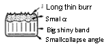 | 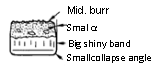 |  | 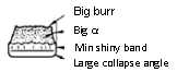 | 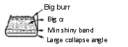 | |
| Kick angle R | (2-5)%t | (4-7)%t | (6-8)%t | (8-10)%t | (10-12)%t | |
| Bright band height B | (50-70)%t | (35-55)%t | (25-40)%t | (15-25)%t | (10-20)%t | |
| Fracture zone height F | (25-45)%t | (35-50)%t | (50-60)%t | (60-75)%t | (70-80)%t | |
| Burr height h | Slender | Medium | Average | High | Higher | |
| Break angle a | – | 4°-7° | 7°-8° | 8°-11° | 14°-16° | |
| Flatness f | Good | Fairly good | Average | Poor | Worse | |
| Dimensional accuracy | Blanking piece | Very close to the die size | Close to the die size | Slightly smaller than the die size | Less than the die size | Less than the die size |
| Punching piece | Very close to the punch size | Close to the punch size | Slightly larger than the punch size | Greater than the punch size | Greater than the punch size | |
| Punching force | Larger | Large | Average | Small | Smaller | |
| Discharge force,Push force | Large | Larger | Smallest | Smaller | Small | |
| Die life | Low | Lower | Higher | High | Higher | |
Table 3-20 Blanking value of metal sheet (GB / T16743-2010)
| Materials | Shear strength Mpa | Initial gap (unilateral gap)%t | ||||
| Class i | Class ii | Class iii | Class iv | Class v | ||
| Mild steel 08F, 10F, 10, 20, Q235-A | ≥210-400 | 1.0-2.0 | 3.0-7.0 | 7.0-10.0 | 10.0-12.5 | 21.0 |
| Medium carbon steel 45, stainless steel 1Cr18Ni9Ti, 4Cr13, expansion alloy (Kovar) 4J29 | ≥420-560 | 1.0–2.0 | 3.5-8.0 | 8.0-11.0 | 11.0-15.0 | 23.0 |
| High carbon steel T8A, T10A, 65Mn | ≥590-930 | 2.5-5.0 | 8.0-12.0 | 12.0-15.0 | 15.0-18.0 | 25.0 |
| Pure aluminum 1060, 1050A, 1035, 1200, aluminum alloy (soft) 3A21, brass (soft) H62, pure copper (soft) T1, T2, T3 | ≥65-255 | 0.5-1.0 | 2.0-4.0 | 4.5-6.0 | 6.5-9.0 | 17.0 |
| Brass (hard) H62, lead brass HPb59-1, pure copper (hard) T1, T2, T3 | ≥290-420 | 0.5-2.0 | 3.0–5.0 | 5.0-8.0 | 8.5-11.0 | 25.0 |
| Aluminum alloy (hard) ZA12, tin phosphor bronze QSn4-2.5, aluminum bronze QA17, beryllium bronze QBe2 | ≥225-550 | 0.5-1.0 | 3.5-6.0 | 7.0-10.0 | 11.0-13.5 | 20.0 |
| Magnesium alloy MB1, MB8 | 120-180 | 0.5-1.0 | 1.5-2.5 | 3.5-4.5 | 5.0-7.0 | 16.0 |
| Electrician silicon steel | 190 | – | 2.5-5.0 | 5.0-9.0 | – | – |
(3) Selection method of blanking gap
When selecting metal sheet blanking clearances, according to the technical requirements of the blanking parts, the use characteristics and specific production conditions, etc., first determine the type of clearance to be adopted according to Table 3-19, and then select this type gap value accordingly according to Table 3-20.
The gap of the new mold should be the smallest of the gap values.
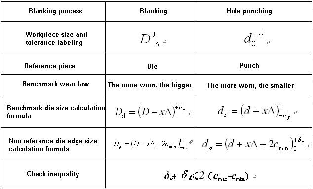
2.Determining the dimensions and tolerances of punch and die cutting edges
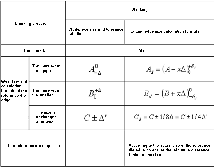
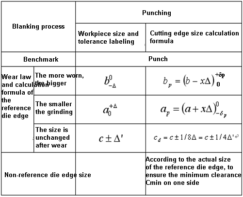
(1) Calculation principle of the cutting edge size of punch and dies
- When blanking, select the die as the reference, first design the die edge size, and the gap is obtained by reducing the die edge size.
- When piercing, the punch is selected as the reference. The punch edge size is first designed, and the clearance is obtained by increasing the punch edge size.
- The size of the reference die edge with the increased size after wear is equal to or close to the minimum limit size of the workpiece; the size of the reference die with the reduced size after wear is equal to or close to the maximum limit size of the workpiece. For the size of the cutting edge that does not change before and after the wear, it is equal to the size of the workpiece.
- In principle, the manufacturing tolerances of workpiece dimensions and die cutting edge dimensions are marked as one-way deviations according to the “in-body”principle, that is, the blanking part and punch edge sizes are marked as one-way negative deviations, piercing parts and die cutting edges. Dimensions are marked as unidirectional positive deviations, and dimensions that do not change after abrasion are generally labeled as bidirectional deviations.
(2) Calculation method of cutting edge size
The calculation method of the cutting edge size is related to the mold processing method. There are two common mold processing methods:
- Separate processing
- Cooperative processing method
Comparison of two mold processing methods
| Mold processing method | Separate processing method (interchange processing method) | Cooperative processing |
| Definition | The punch and the die are respectively machined to the final size according to their respective drawings. | The reference die is machined first, and the edge size of the non-reference die is configured according to the actual size of the already-cut reference die edge in accordance with the minimum reasonable clearance. |
| Advantages | (1) The punch and die can be manufactured in parallel, which shortens the manufacturing cycle of the mold; (2) Mold parts can be interchanged | (1) The mold gap is guaranteed by the preparation, which reduces the difficulty of mold processing; (2) It is only necessary to draw a detailed reference model part drawing to reduce the drawing workload. |
| Disadvantages | (1) It is necessary to draw a part drawing of the punch and die separately; (2) The mold gap is ensured by the precision of the mold processing, which increases the processing difficulty of the mold. | The non-reference mold must be manufactured after the reference mold is manufactured, and the mold manufacturing cycle is long. |
| Application | With the development of mold manufacturing technology, most of the molds in actual production are manufactured by separate processing methods, and the application of processing methods is becoming less and less. . | |
1) Separate processing of male and female dies
Wear coefficient x value
| Material thickness t/mm | Non-circular workpiece x value | Circular workpiece x value | ||||
| 1 | 0.75 | 0.5 | 0.75 | 0.5 | ||
| Workpiece tolerance Δ/mm | ||||||
| 1 | <0.16 | 0.17~0.35 | ≥0.36 | <0.16 | ≥0.16 | |
| 1~2 | <0.20 | 0.21~0.41 | ≥0.42 | <0.20 | ≥0.20 | |
| 2~4 | <0.24 | 0.25~0.49 | ≥0.50 | <0.24 | ≥0.24 | |
| >4 | <0.30 | 0.31~0.59 | ≥0.60 | <0.30 | ≥0.30 | |
Example of calculation of cutting edge size
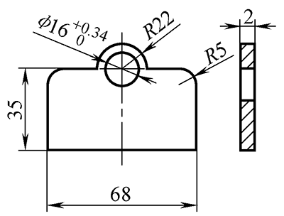
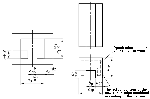
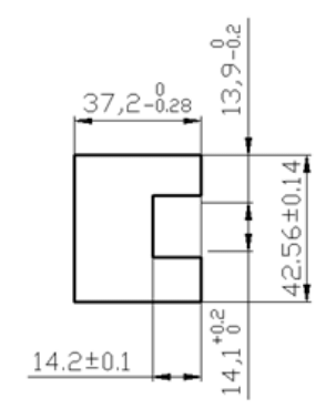
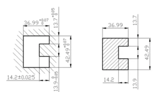
Example 3-7 The part shown in Figure 3-73 is punched out. The material is Q235, and the material thickness is t = 2mm. Calculate punching and die cutting edge dimensions and tolerances.
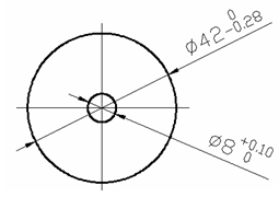
Solution: As shown in Figure 3-73, this part requires two blanking processes, namely blanking and piercing. The die edge size and tolerance are calculated below.
1) Blanking
Based on the concave mold, due to the regular shape, the mold is processed separately.
Checking Table 3-19 and Table 3-20 get c = (7% ~ 10%) t, that is:
cmin =7%t=0.07×2=0.14mm;
cmax=10%t=0.10×2=0.2mm;
Look up the table 3-24 to get the wear coefficient: x = 0.5;
The manufacturing deviations of the convex and concave molds obtained by looking up in Table 3-25 are: δp = 0.014mm, δd = 0.02mm;
Calculated from the formula:
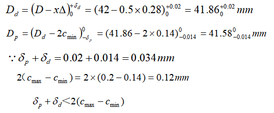
Therefore, the accuracy of the mold is appropriate.
2) Piercing
Taking the punch as the reference, because the hole shape is simple, the separate manufacturing method is used to process the mold.
Look up the table 3-24: χ=0.75
Check the table 3-25 to get: δp = 0.012mm, δd = 0.017mm
Calculated from the formula in Table 3-23:
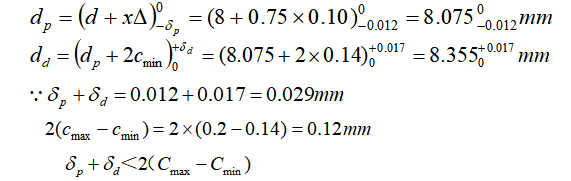
Therefore, the accuracy of the mold is appropriate.
2) Coordinate processing of male and female dies

Calculation formula of blanking die edge size during cooperative processing
Calculation formula of punching die edge size during cooperative processing
Example drawing of convex and concave parts when using the machining method
Pay attention to the dimension tolerance of the cutting edge
3.Structural design of working parts and selection of standards
(1)Structural form of convex die and its fixing method
Problems to be solved when designing punches
- Structure type
- Fixed way
- Size design
- Material selection
- Heat treatment requirements
- Check
According to the cross-sectional shape, there are circular cross-section punches and irregular cross-section punches.
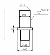
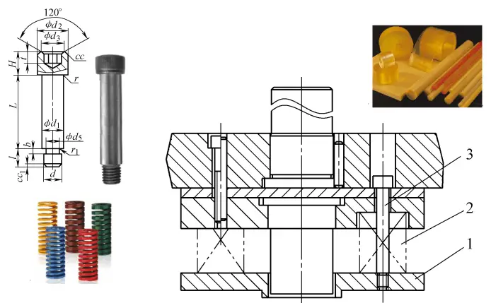
1) Structural form and fixing method of standard round convex die (JB / T5825-2008 ~ JB / T5829-2008)
- Cylindrical straight round convex die (rod diameter φD = 1 ~ 36mm)
- Cylindrical head shrink rod round convex die (rod diameter φD = 5 ~ 36mm)
- Cone-head straight rod round punch (edge diameter φD = 0.5 ~ 15mm)
- 60°conical head round rod die (rod diameter φD = 2 ~ 3mm)
- Ball locking round punch (diameter φD = 6.0 ~ 32mm)
Recommended materials: Cr12MoV, Cr12, Cr6WV, CrWMn
Hardness requirements: Cr12MoV, Cr12, Cr6WV cutting edge 58 ~ 62HRC, head fixed part 40 ~ 50HRC; CrWMn cutting edge 56 ~ 60HRC, head fixed part 40 ~ 50HRC
Structure and fixing method of cylindrical head shrink rod circular convex die
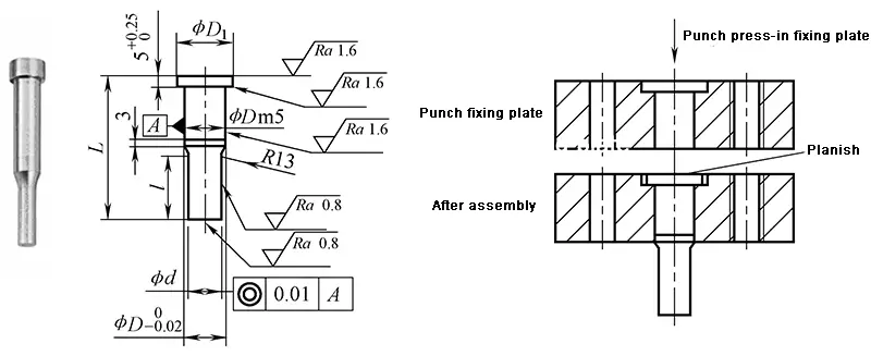
Standard dimensions and marking examples of cylindrical head shrink rod circular punch(JB/T5826-2008)
Marking example: D = 5mm, d = 2mm, L = 56mm cylindrical shrink pin circular punch die marking: cylindrical shrink pin circular punch 5×2×56 JB / T5826-2008
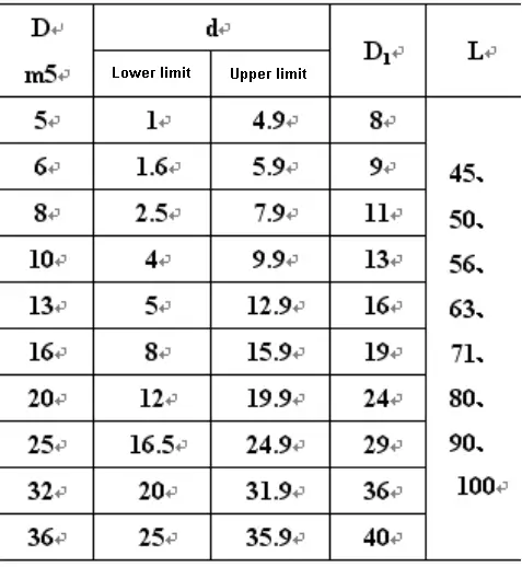
Structural form and fixing method of large and medium circular convex dies
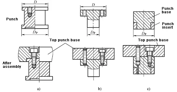
Structure and fixing method of piercing punch
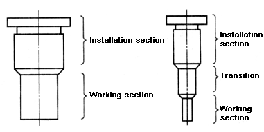
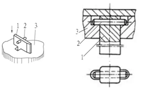
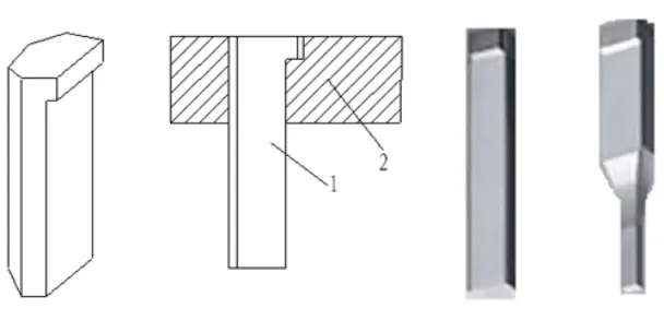
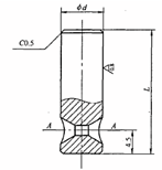
2) Structural form and fixing method of special-shaped convex die
- Stepped structure: fixed part is round or rectangular
- Straight-through structure

Special-shaped convex die adopts step structure and fixing method
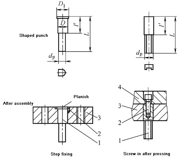
Fixed side slotted special-shaped punch with a pressure plate
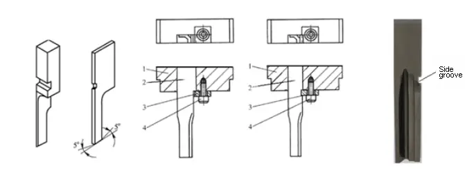
Fixing profiled punch with transverse pin
Fixing the profiled punch with a hanging platform
3)Determination of the size of the punch—related to the mold structure

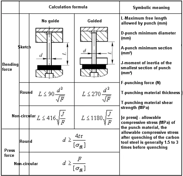
(3) Strength check of the punch
- Check of pressure capacity
- Anti-stability check
(2) Die structure design and selection of standards
- Female die structure and fixing method
- Die edge design
- Die design
- Selection of die material
- Die heat treatment requirements
1) Structural form and fixing method of the die
- Integral
- Combined
- Block type
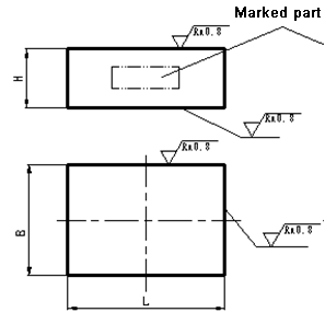
Integral die—structure commonly used in ordinary stamping dies.
There are two types of integral die: rectangular and round.
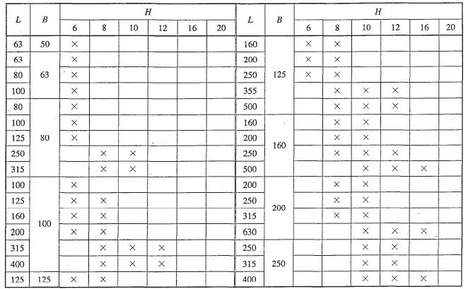
Marking example: L = 125mm, B = 100mm, H = 20mm rectangular concave mold marking: rectangular concave template 125×100×20 JB / T7643.1-2008
Integral die fixing method:
Recommended materials:
- T10A,
- 9Mn2V,
- Cr12,
- Cr12MoV
- Heat treatment hardness: 60 ~ 64HRC
Fixing method-screws and pins are directly fastened in the lower mold base
Combined die structure and fixing method
Recommended materials:
- Cr12MoV
- Cr12
- Cr6WV
- CrWMn
- Heat treatment hardness: 58 ~ 62HRC
Block die
2) Cutting edge form of the die

3) Shape design of the die—shape and size
Shape: round or rectangular
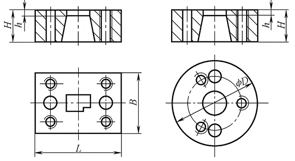
Die Dimension Design——Empirical Formula

The calculated size of the shape of the die obtained from this is:


Design steps of blanking die:

Example of Die Shape Design


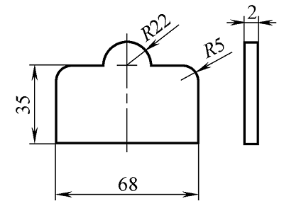
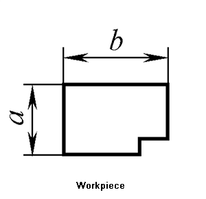
Example 3-9 Try to design the shape and dimensions of the blanking die for the workpiece shown in Figure 3-92.
Solution: Because the shape of the punch is close to a rectangle, the shape of the die is rectangular.
According to the maximum external dimensions of the workpiece b = 40 + 20 = 60mm and the thickness of the material is 2mm, check Table 3-29: K = 0.28, then the dimensions of the die can be calculated as follows:
H = Kb = 0.28×60 = 16.8mm
c = (1.5 ~ 2) H = (1.5 ~ 2)×16.8 = 25.2mm ~ 33.6mm,
Take c = 30mm.
Then: L = 40 + 19.88 + 30×2 = 119.88mm
B = 19.88 + 30×2 = 79.88mm
This is the calculated external dimensions of the die. According to the calculated dimensions in Table 3-31, we know that the actual die size should be:
L×B×H = 125mm×80mm×18mm
Partial data of rectangular concave template

(3) Design of convex and concave dies
The convex and concave die is a working part in the composite die that has the functions of blanking die and punching die. Its inner and outer edges are cutting edges, and the wall thickness between the inner and outer edges depends on the size of the blanking part.
Minimum wall thickness of male and female die
| Sketch | 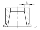 | |||||||||
| Thickness t/mm | 0.4 | 0.5 | 0.6 | 0.7 | 0.8 | 0.9 | 1.0 | 1.2 | 1.5 | 1.75 |
| Min wall thickness a/mm | 1.4 | 1.6 | 1.8 | 2.0 | 2.3 | 2.5 | 2.7 | 3.2 | 3.8 | 4.0 |
| Thickness t/mm | 2.0 | 2.1 | 2.5 | 2.7 | 3.0 | 3.5 | 4.0 | 4.5 | 5.0 | 5.5 |
| Min wall thickness a/mm | 4.9 | 5.0 | 5.8 | 6.3 | 6.7 | 7.8 | 8.5 | 9.3 | 10.0 | 12.0 |
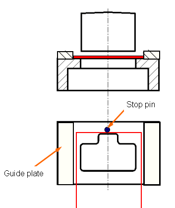
6.2 Design of positioning parts and selection of standards
Role: Determine the exact position of the blank in the mold
There are two forms of blanks fed into the mold:
- Strip (strip or coil)
- Single blank

The strip is “advanced” along the mold

Individual blanks are “placed” in the designated position of the mold
Example of single blank positioning
- Leader parts
The role is to ensure that the strip is fed into the mold in the correct direction
Common lead parts are:
- Guide plate
- Guide pin
- Side pressure device
(1) Guide plate
The role is to control the feeding direction of the strip
Usually two pieces, distributed on two sides of the feeding direction of the strip, and directly fixed to the die with screw pins. There are two forms:
- Standard structure: Recommended material 45 steel, heat treatment hardness 28 ~ 32HRC
- Non-standard structure: guide plate and discharge plate as a whole
Fixing method of standard structure guide plate
The dimensions of the guide plate and the concave template are the same.
Non-standard structure guide plate

The guide plate and the discharge plate are integrated
Structure with receiving plate
The guide plate is longer than the concave template
(2) Guide pin
Generally, at least two are required, and they are located on the same side of the strip. The standard structure is recommended. The material is 45 steel and the heat treatment hardness is 43 ~ 48HRC.
(3) Side pressure device
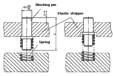
- Retaining parts
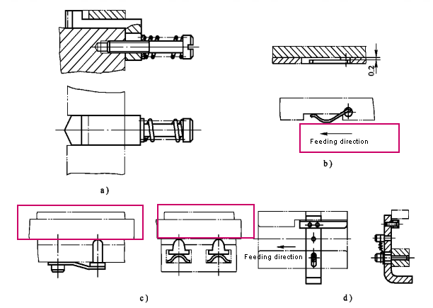
The role is to control the distance that the strip is fed into the mold, that is, the control of the distance. Common structures include material blocking pins, side edges, guide pins, and so on.
The blocking pin is divided into fixed blocking pin and movable blocking pin.
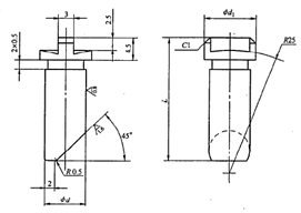
The fixed stopper pin includes round head stopper pin and hook-shaped stopper pin.
The movable stopper pin includes: initial stopper pin, return-type stopper pin, and top elastic stopper pin.
(1) Fixed stopper pin
The function is to control the feeding distance of the strip, that is, to control the feeding distance of the standard part. It is directly fixed to the die in front of the feeding.
Selection basis: Thickness t of punched sheet, see Table 3-34

Working principle of fixed stop pin

Hook stopper pin

(2)Active stopper pin
All are standard structure, 45 steel is recommended for the material of block or pin, heat treatment hardness is 43 ~ 48HRC
The starting material blocking device is usually installed in the guide plate, and it is mostly used for the first feeding of the progressive die.

Bullet stopper device
It is installed in the elastic discharge plate, and it is mostly used in the flip-type compound mold.
There are three forms:
- Spring-loaded material blocking device
- Rubber dome blocking device
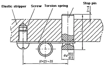
- Torsion spring ejection material blocking device
Spring-loaded material blocking device

Rubber dome blocking device


Torsion spring ejection material blocking device
Belt-feeding stopper
Installed in a rigid discharge plate, mostly used in manual feeding molds

The working principle of the belt-type blocking device

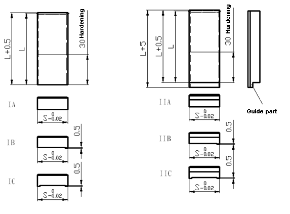
(3) Side blade
The function is to control the feeding distance of the strip, that is, to control the feeding distance.
Side edge: In the progressive die, in order to limit the feeding distance of the strip, a work piece with a certain shape is punched out at the side of the strip.
The side blade has standard parts, and T10A is recommended. The heat treatment hardness is 56 ~ 60HRC.
Standard side blade selection method: According to the distance, the edge length of the side edge = the distance
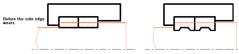
Standard side edge
Location of burrs after blunt side cutting
Special side blade
Non-standard parts are determined by the shape of the punch.
Side edge stop

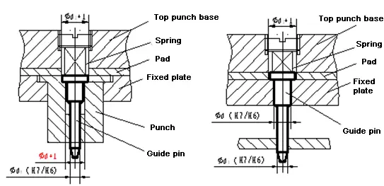
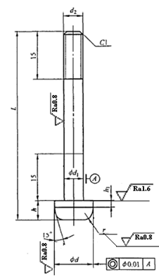
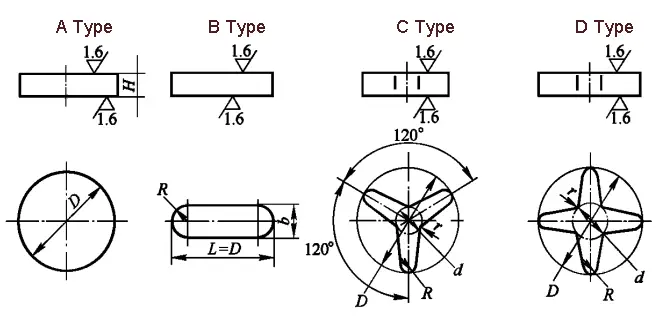
(4) Guide pin
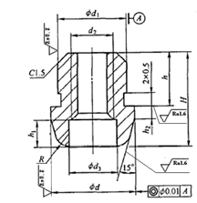
Mainly used for precise positioning of the strip in the progressive die. It is a standard part. It consists of head and rod. The rod of the guide pin is used for fixing. The guide pin is recommended to use 9Mn2V based on the pre-punched hole diameter d.
Basic size:
- Leading part diameter d——use H7 / h6 or H7 / h7 to cooperate with the guide hole
- Height of the guiding part h——take h = (0.8 ~ 2) t

Structure and fixing method of standard A type guide pin

A type guide pin

Structure and fixing method of standard B type guide pin

B type guide pin
Structure and fixing method of standard C guide pin
C type guide pin

Structure and fixing method of standard D-type guide pin
D type guide pin
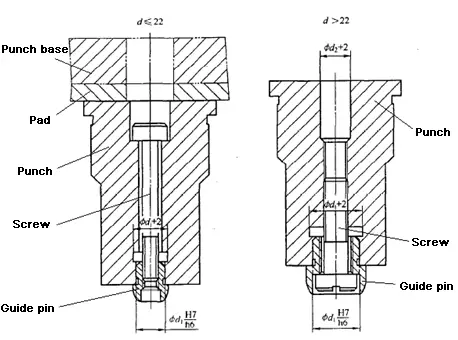
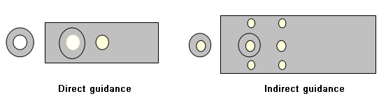
Two ways of guiding pins:
The guide pin can align directly or indirectly.
- Direct alignment refers to the use of holes in the workpiece for alignment. The alignment pins are usually installed in the blanking die.
- Indirect alignment is to use the pre-punched process holes for alignment, and the alignment pins are often installed in the convex die fixing plate.
Guide pins cannot be used independently! !!
The guide pin is usually used in conjunction with a blocking pin, a side edge and an automatic feeding device.
Positional relationship with the blocking pin:

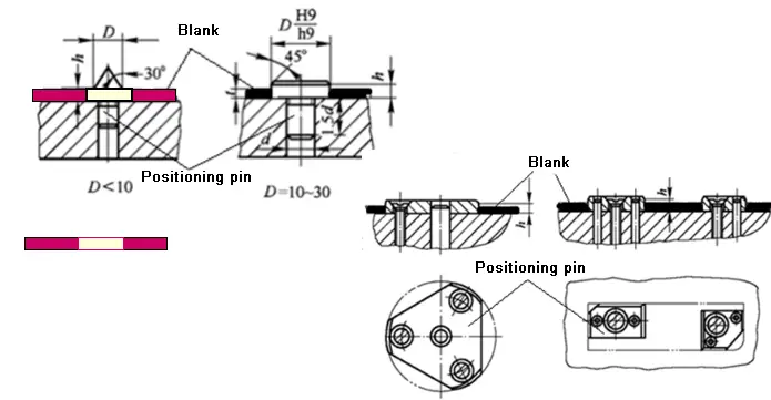
(3) positioning plate and positioning pin
Positioning using blank shape
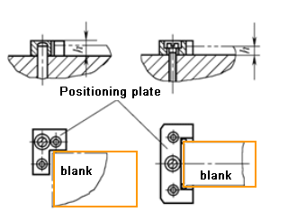
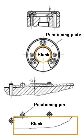
Positioning using blank inner shape
6.3 Design and standard selection of pressing, discharging and feeding parts
The role is to hold the sheet and unload or push out parts and scrap
- Unloading device (waste cutter)
- Pusher device
- Ejectingdevice
- Unloading device
The purpose is to remove the parts or scraps hooped outside the male or female die.
According to different sources of discharge force:
- Rigid discharge device
- Flexible discharge device
- Waste cutting knife (for unloading when drawing deep-edged parts)
(1) Rigid (fixed) unloading device
It consists of a plate (called discharge plate), which is directly fixed on the die with screws and pins. The discharge force is caused by the rigid impact between the blank of the plate and the discharge plate. It is mainly suitable for thick plate unloading with large unloading force and no requirement for plate flatness.

Unloading principle of rigid unloading device

The force caused by the rigid impact of the discharge plate and the material is used for unloading.
(Rigid) discharge plate design

- The shape and size of the outer shape are generally the same as the die
- The hole shape depends on the shape of the punch for this punching, and there is a gap between the two. If it acts as a guide plate at the same time, a clearance fit of H7 / h6 is used with the punch.
- The thickness of the discharge plate is determined by the thickness of the plate, see the table below.
- The material is recommended to be 45 steel, and the hardness is 43 ~ 48HRC.
| Sheet Thickness
t(mm) | Stripper width B(mm) | |||||||||
| ≤50 | 50~80 | 80~125 | 125~200 | >200 | ||||||
| S | S’ | S | S’ | S | S’ | S | S’ | S | S’ | |
| 0.8 | 6 | 8 | 6 | 10 | 8 | 12 | 10 | 14 | 12 | 16 |
| 0.8~1.5 | 6 | 10 | 8 | 12 | 10 | 14 | 12 | 16 | 14 | 18 |
| 1.5~3 | 8 | – | 10 | – | 12 | – | 14 | – | 16 | – |
| 3~4.5 | 10 | – | 12 | – | 14 | – | 16 | – | 18 | – |
| >4.5 | 12 | – | 14 | – | 16 | – | 18 | – | 20 | – |
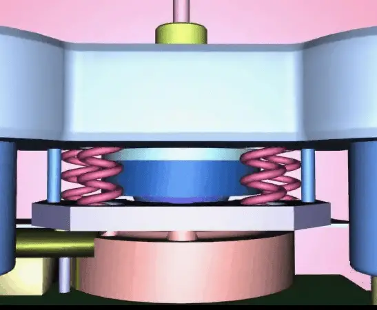
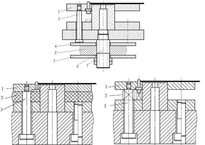
(2) Elastic discharge device
It consists of a discharge plate, an elastic element and a discharge screw. It is usually installed in the upper mold and can also be installed in the lower mold.
The discharge force is caused by the compression of the elastic element.
This type of discharge plate is often used for punching with thin materials, small discharge force, and plate flatness requirements.

Working process of elastic discharge device
Several structural forms of elastic discharge device
Unloading device is installed on the upper mold
Unloading device installed in the lower mold
Need to design: discharge plate, elastic element and discharge screw.
In general, the shape and size of the discharge plate are consistent with the die. If there are too many or too large elastic elements, the size of the discharge plate is allowed to be increased to facilitate the placement of the elastic element.
The hole pattern of the discharge plate is consistent with the shape of the punching die. There is a certain gap between the two. The thickness of the discharge plate depends on the thickness of the punched plate.
The discharge screw is a standard part (unlike the fixing screw, which is dedicated to the mold) and can be directly selected from the standard.
Commonly used elastic elements are springs and rubbers, which are standard parts and can be selected according to conditions.
Connection of elastic discharge device-discharge screw
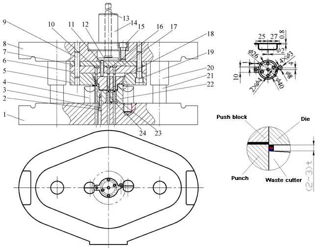
(3) Waste cutting knife
When cutting the drawn part, use a scrap cutter to discharge.
The waste cutting knife is usually installed on the edge of the cutting punch, and its cutting edge is about 2 to 3 thicker than the cutting edge. When blanking, the die presses the waste down on the cutting edge of the cutting blade to cut the waste for unloading.

Standard structure of waste cutter

- Pusher device
The role is to push the workpiece or scrap stuck in the cavity of the die along the punching direction.
Depending on the source of the thrust force:
- Rigid pusher device
- Elastic pusher device
(1) Rigid pusher device

Components of rigid pusher device
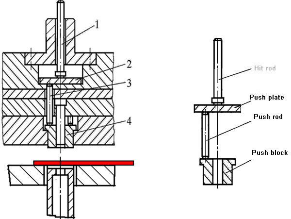
Principle of rigid pusher device

Design of rigid pusher device

Design of pusher block

Push plate structure: optional standard parts
Elastic pusher device
- Composed of elastic elements and pusher blocks
- Need design: pusher block and elastic element.

- Ejection device
The effect is to push out the material stuck in the cavity of the die against the direction of punching.

Working process of top device

6.4 Design of guide parts and selection of standards
The role is to ensure movement guidance and determine the relative positions of the upper and lower dies. The purpose is to make the male dies enter the female dies correctly, and make the peripheral clearances of the male and female dies as uniform as possible.
- Guide column guide sleeve: sliding guide column guide sleeve; ball guide column guide sleeve
- Guideplate
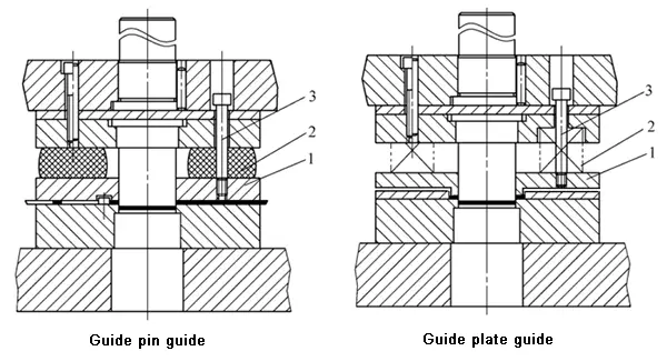
(1) Guide post and guide bush guide
Sliding guide post guide sleeve

Sliding guide post guide sleeve is standard

Assembly of sliding guide post and guide sleeve

Ball guide post guide sleeve

Ball guide
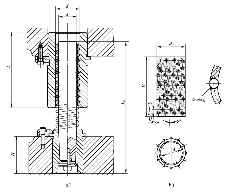
- a) Ball guide
- b) Steel ball cage
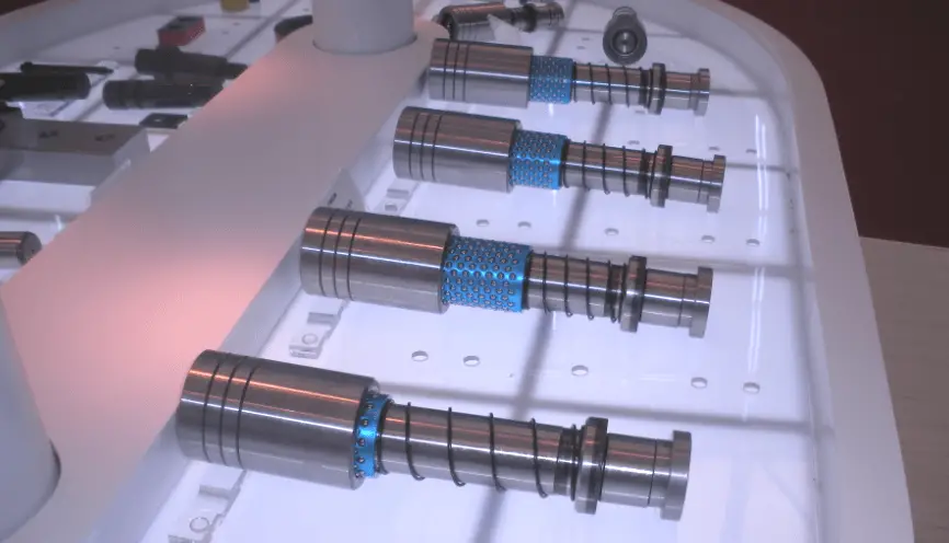
Ball guide
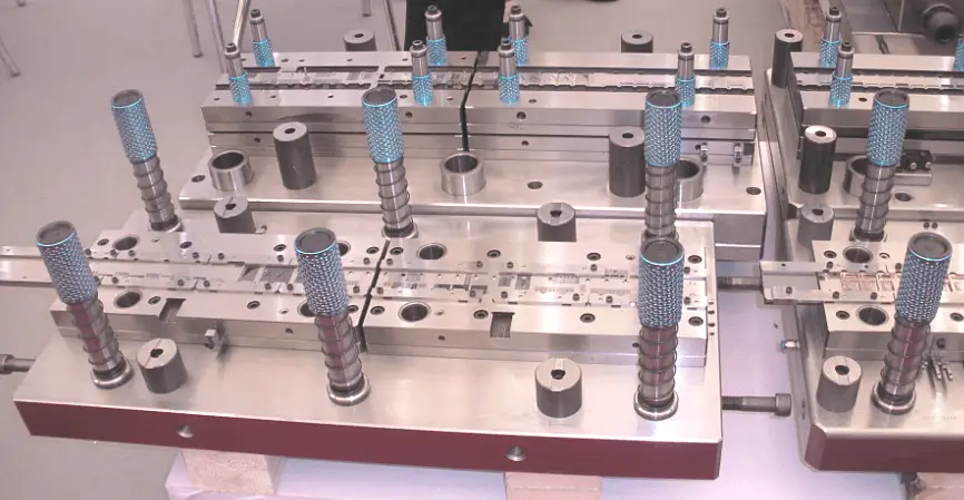
The installation position of the ball guide post guide sleeve in the mold
(2) Guide plate guide
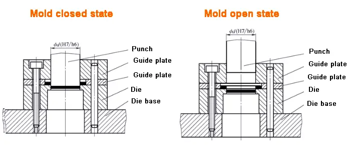
The guide plate is a rigid discharge plate.
The difference is that the gap between the guide plate and the punch is H7/h6. To ensure that the guide plate plays a guiding role, the guide plate should have sufficient contact length with the punch. The thickness H is generally taken as:
H = (0.8~1) Hdie (Hdie is the thickness of the die)
At the same time, during the entire working process of the mold (including the return of the mold), the punch and the hole of the guide plate are not separated.
6.5 Design and standard selection of connecting and fixing parts
The role is to fix the male and female dies on the upper and lower dies, and the upper and lower dies on the press. include:
- Mold base (frame)
- Die handle
- Pad
- Fixing plate
- Screw
- Pin
(1) Mold base
There are upper mold base and lower mold base, which are used to assemble and support the parts used for the upper mold or the lower mold.
Standard formwork
- Upper mold base
- Lower mold base
- Guide post
- Guide sleeve
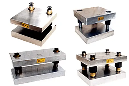
Depending on the fit of the guide post and guide sleeve, the standard formwork includes:
- Sliding guide formwork
- Rolling guide formwork
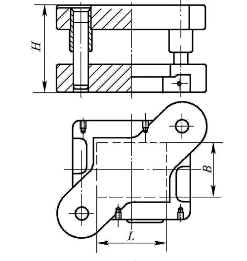
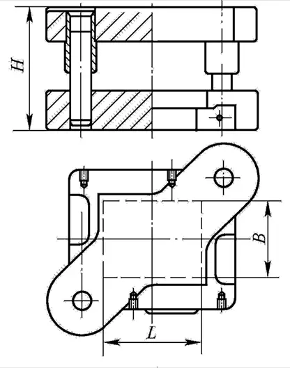
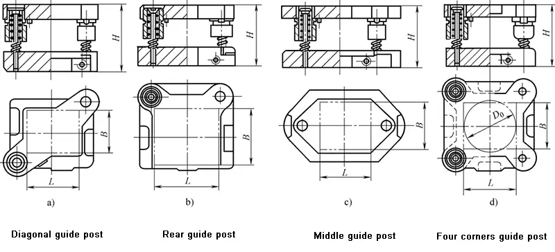
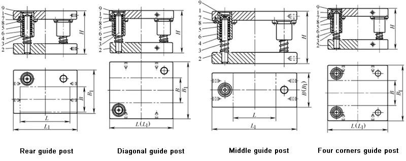
Depending on the position of the guide post and guide sleeve, the standard formwork includes:
- Diagonal guide post formwork
- Rear guide post formwork
- Intermediate guide post formwork
- Four corner guide post formwork
Standard mold base-upper mold base, lower mold base, guide post, guide sleeve
Sliding guide standard formwork

Sliding guide steel formwork
Mold base selection principle: Select according to the perimeter of the die

(2) Mold handle-standard parts
The role is to fix the upper mold on the slide of the press, which is usually applied to small and medium-sized molds.
The common standard handles are:
- Press-in mold handle
- Screw-in mold handle
- Flange mold handle
- Floating mold handle
Mould material is recommended to use Q235A or #45 steel.
Selection principle: the diameter of the die handle hole of the press
Four standard structures of common mold handles

(3) Fixed plate
The role is to install and fix small male or female molds, and finally install them on the upper mold base or the lower mold base as a whole.
It is a standard part and is available in two types: rectangular and circular.

Design of the fixing plate
The selection of the male die fixing plate is based on the shape and size of the female die.
- The plane size of the fixed plate is the same as that of the die, and the thickness is generally 0.6 to 0.8 times the thickness of the die.
- The mounting holes and punches of the fixing plate adopt a transition fit H7 / m6 or H7 / n6 or H7 / m5. After pressing, the end surfaces of the fixing plate and the fixing plate are ground together.
- It is recommended to use 45 steel as the fixing plate material, and the heat treatment hardness is 28 ~ 32HRC.
Rectangular fixing plate

(4) Backing plate

It is located between the convex and concave molds and the mold base, and bears and disperses the pressing load to prevent the upper and lower mold bases from being pressed out of the recess.
Whether a pad is used in the mold depends on two conditions:
- The unit pressure generated by the fixed end surface of the punch on the mold base exceeds the pressure that the mold base can withstand.
That is: σ = P / F≥ [σpress]
- The use of a rigid pusher device in the upper mold requires machining of holes in the mold base.
Plate design
The backing plate is a standard part, which has a round backing plate (JB / T7643.6-2008) and a rectangular backing plate (JB / T7643.6-2008).
Selection basis is the shape and size of the die.
- The plane size of the backing plate is the same as that of the die, and the thickness is generally 5-12mm.
- 45 steel is recommended as the material, and the heat treatment hardness is 43 ~ 45HRC.
- When designing a composite mold, a pad should sometimes be installed between the convex and concave molds and the mold base.
Backing plate standard

(5) Screws and pins-standard parts
The fastening parts in the mold mainly include screws and pins. The screw mainly connects the parts in the die to make it a whole, and the pin plays the role of positioning. Hexagon screws are the best choice for screws. Cylindrical pins are often used for pins. When designing, there must be no less than two cylindrical pins.
The distance between the pin and the screw should not be too small to prevent the strength from decreasing. The specifications, quantities, distances, and other dimensions of the screws and pins in the mold can be designed by referring to the typical combination of cold die in the national standard.
The diameter of the screw is determined by the thickness of the die.
Selection of screw diameter
| Die Thickness | <13 | 13-19 | 19-25 | 25-32 | >32 |
| Screw diameter | M4,M5 | M5,M6 | M6,M8 | M8,M10 | M10,M12 |
Selection and check of blanking equipment
7.1 Selection of equipment
The selection is based on the size of the blanking process force and the mold structure.
The selection steps are:
(1) Calculate the total blanking force F total according to the mold structure characteristics.
When using the rigid discharge device and the lower discharge method, the total blanking process force is:
Ftotal=F+FT
When the elastic discharge device and the upper discharge method are used, the total blanking process force is:
Ftotal=F+FX+FD
When using the elastic discharge device and the lower discharge method, the total blanking process force is:
Ftotal=F+FX+FT
(2) Check the equipment data according to the total blanking process power, set the nominal pressure F of the equipment ≥ Ftotal, and then select the equipment initially and get the relevant parameters of the equipment.
7.2 Primary selected equipment after checking

(1) Check the closed height
(2) Checking the plane size
(3) Check the size of the mold handle hole
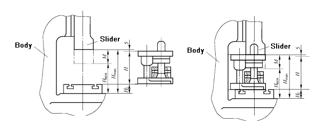
The closing height of the press refers to the distance from the bottom surface of the slider to the upper surface of the table when the slider is in the lower limit position. The closing height of the press has a maximum closing height Hmax and a minimum closing height Hmin.

The closing height H of the mold refers to the distance between the lower plane of the lower mold base and the upper plane of the upper mold base when the mold is at the lower pole of the working position.
Hmax-5mm≥H≥Hmin+10mm
Relationship between mold and equipment