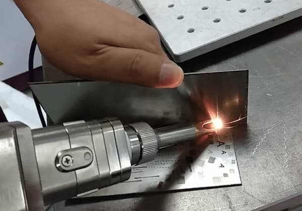
Laser welding equipment utilizes high-energy laser pulses to focus and melt the target metal, thereby welding the workpieces together
The new welding technology has a positive effect, however, if not handled correctly, it can result in hot or cold cracks.
What causes welding cracks in a laser welding machine?
Metallurgical factors
The unbalanced rapid heating and cooling during laser welding creates a complex stress state in the joint, which is a mechanical factor that contributes to cracking.
Laser welding is a series of unbalanced processes, leading to an uneven distribution of components and a hardened structure with low resistance to cracking during rapid solidification. This constitutes a metallurgical factor that promotes crack initiation.
Mechanical factors
There are three types of cracks that can occur during the welding process of a laser welding machine: product cracks, liquefaction cracks, and reheat cracks.
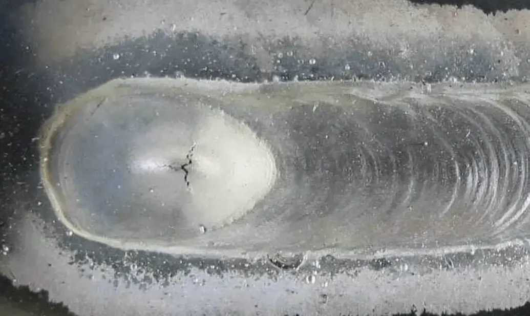
The crystal crack is a result of the non-uniform composition in the macro region of the weld.
The central area of the weld is where liquid phase crystallization occurs last, and where the columnar crystals on both sides of the weld meet.
Unfortunately, a large number of impurities with low melting points also accumulate in this area, resulting in centerline segregation which weakens the bond strength.
Under certain mechanical conditions, cracks can occur at this location.
Therefore, it is important to promptly identify and resolve any cracks that do occur.
So, what can be done to reduce the occurrence of welding cracks in a laser welding machine?
There are two main measures:
Changing parameters of laser welding machine
The primary causes of thermal cracks during pulse laser welding are due to the solidification of the weld after the laser welding process. During this process, the weld passes through a temperature range with low plasticity, which is referred to as the brittle temperature zone.
The crystallization of the weld metal is influenced by tensile stress, which is caused by the difficulty of the welded metal to shrink.
This tensile stress results in elastic-plastic deformation in the weld.
If the weld metal is in the brittle temperature zone and the plastic deformation exceeds the metal’s plasticity, cracks will form.
Reasonably improve the alloy system of the material according to the nature of the crack
The causes of cold cracks during pulse laser welding occur during the cooling process. A martensitic structure forms near the seam and welding stress, as well as microstructural stress, are generated.
The metal with a martensitic structure has high strength but low plasticity and residual stress remains in the welding metal during the cooling process.
In the case of ferritic or austenitic quenched steel, the stress state of the welded joints is characterized by the formation of longitudinal compressive stress near the weld area. This is caused by the martensitic transformation that occurs in this area during welding.
These types of stresses can result in the formation of cold cracks.
Causes of thermal crack:
The occurrence of thermal cracks during laser welding depends on various factors, including the chemical composition of the weld metal and the surrounding area, the conditions and characteristics of the crystallization process, the extent of chemical and physical micro heterogeneity, the size of deformation, and the rate at which deformation grows.
At present, the mechanism of crystal crack formation is described as follows:
During the solidification process of a plate bending machine, the weld of the laser welding machine goes through a temperature range with low plasticity, referred to as the brittle temperature zone.
The crystallization of the weld metal is influenced by tensile stress, which is caused by the difficulty of the welded metal to shrink.
The presence of tensile stress leads to elastic-plastic deformation in the weld.
If the weld metal is in the brittle temperature zone and the plastic deformation exceeds the metal’s plasticity, a crack will form.