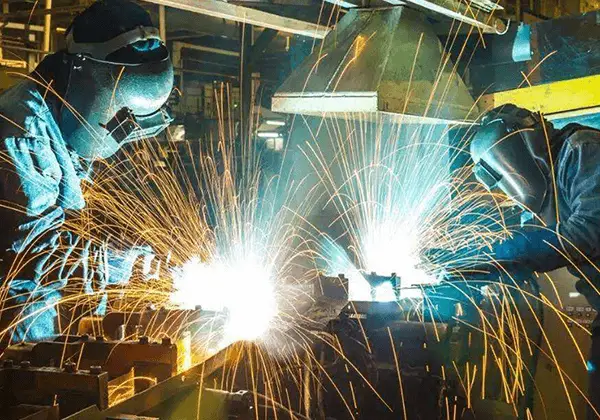
There are several welding techniques for aluminum alloys, each with its own specific uses. Besides the conventional fusion, resistance, and gas welding methods, other advanced techniques such as plasma arc welding, electron beam welding, and vacuum diffusion welding can also effectively weld aluminum alloys.

1. Common Welding Methods for Aluminum Alloy
The common welding methods for aluminum alloys and their respective characteristics and application scope are presented in Table 1.
Table 1 Characteristics and application scope of common welding methods for aluminum alloy
| Welding method | Characteristic | Scope of application |
|---|---|---|
| Gas welding | Low thermal power, large deformation of weldment, low productivity, easy to produce slag, cracks and other defects | It is used for butt welding and repair welding of thin plate in non important occasions |
| Manual arc welding | Poor joint quality | Used for repair welding and general repair of cast aluminum parts |
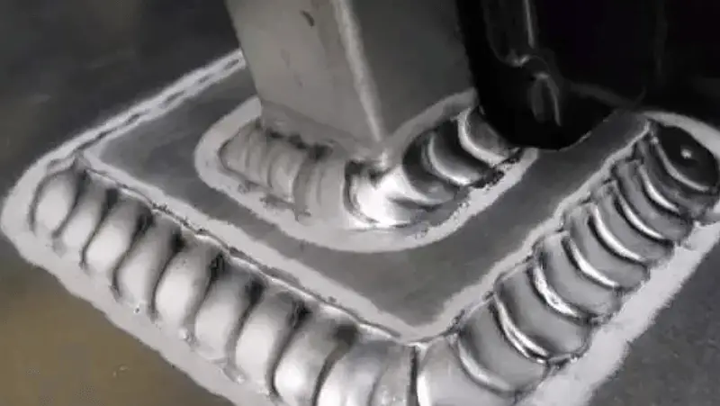
| TIG welding | The weld metal is compact, the joint has high strength and good plasticity, and the high quality joint can be obtained | It is widely used and can be welded with plate thickness of 1 ~ 20mm |
| Pulsed TIG welding | The welding process is stable, the heat input is accurate and adjustable, the deformation of weldment is small, and the joint quality is high | Used for sheet, all position welding, assembly welding and high strength aluminum alloy such as forged aluminum and duralumin with strong heat sensitivity |
| MIG welding | High arc power and fast welding speed | It can be used for welding thick parts with thickness less than 50m |
| MIG pulse argon arc welding | Welding deformation is small, resistance to porosity and crack is good, process parameters are widely adjusted | It is used for sheet or all position welding, and is usually used for workpieces with thickness of 2 ~ 12mm |
| Plasma arc welding | The heat concentration, welding speed, welding deformation and stress is small, the process is more complex | It is used for butt welding where the requirement is higher than that of argon arc welding |
| Vacuum electron beam welding | The results show that the penetration is large, the heat affected zone is small, the welding deformation is small, and the mechanical properties of the joint are good | Used for welding small size weldment |
| Laser welding | Small welding deformation and high productivity | It is used for precision welding parts |
The selection of a welding method for aluminum and aluminum alloys should be based on the grade of the material, the thickness of the component to be welded, the product’s structure, and the desired level of weldability.
Related reading: MIG vs TIG Welding
(1) Gas welding
The thermal power of an oxygen-acetylene welding flame is low, causing heat to be dispersed and resulting in significant weldment deformation and low productivity.
When welding thick aluminum weldments, preheating is necessary.
The weld metal produced by this method has a coarse grain and loose structure, which makes it prone to defects such as alumina inclusion, porosity, and cracking.
This welding method should only be used for repairing unimportant aluminum structural parts and castings with a thickness range of 0.5-10 mm.
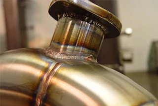
(2) TIG welding
This method, known as TIG welding, is performed under the protection of argon, which results in a more concentrated heat source and stable arc combustion. This results in a denser weld metal with high strength and plasticity, making it widely used in industry.
While TIG welding is an ideal method for welding aluminum alloys, its equipment is complex, making it less suitable for outdoor operations.

(3) MIG welding
The automatic and semi-automatic Gas Metal Arc Welding (GMAW) process has several advantages, including high arc power, concentrated heat, and a small heat-affected zone. Its production efficiency is 2-3 times higher than that of manual GMAW.
GMAW can be used to weld pure aluminum and aluminum alloy plates with a thickness of less than 50mm. For example, preheating is not necessary for aluminum plates with a thickness of 30mm, and only the front and back layers need to be welded for a smooth surface and high-quality weld.
Semi-automatic Tungsten Inert Gas (TIG) welding is ideal for precise welding, short and intermittent welding, and welding on irregular structures.
The semi-automatic argon arc welding torch provides convenient and flexible welding, but the diameter of the welding wire is smaller and the weld is more prone to porosity.
(4) Pulsed argon arc welding
(1) Pulsed Tungsten Inert Gas (TIG) Welding
This method significantly improves the stability of low-current welding processes and allows for easy control of arc power and weld formation by adjusting various parameters. The weldment has minimal deformation and heat-affected zone, making it ideal for welding thin plates, all-position welding, and welding of heat-sensitive materials such as forged aluminum, hard aluminum, and super hard aluminum.
(2) Metal Inert Gas (MIG) Pulse Argon Arc Welding
This method is suitable for all-position welding of aluminum alloy sheets with a thickness of 2-10mm.
(5) Resistance spot welding and seam welding
It can be used to weld aluminum alloy sheets with a thickness of less than 4 mm.
For products with high quality requirements, DC shock wave spot welding and seam welding can be utilized.
Welding requires sophisticated equipment, high welding currents, and high productivity, making it particularly suitable for mass production of parts and components.
(6) Friction stir welding
Friction Stir Welding (FSW) is a type of solid-state joining technology that can be used to weld various alloy plates.
Compared to traditional fusion welding methods, FSW offers several advantages such as the absence of spatter, reduced dust, no need for welding wire or shielding gas, and a lack of pores and cracks in the joint.
Moreover, compared to ordinary friction, FSW is not limited by shaft parts and can produce straight welds.
This welding method also boasts several other benefits, including improved mechanical properties, energy efficiency, reduced pollution, and low preparation requirements prior to welding.
Due to the low melting point of aluminum and aluminum alloys, FSW is particularly well-suited for these materials.

2. Welding Materials for Aluminum
(1) Welding wire
When welding aluminum alloys using gas welding or TIG welding, the use of filler wire is recommended.
Aluminum and aluminum alloy welding wires can be categorized into two types: homogeneous and heterogeneous.
To achieve a strong and reliable welding joint, it is important to choose the appropriate filler material that is suitable for the base metal being used.
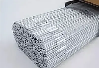
When selecting a welding wire for aluminum alloys, it is important to consider several factors, including the composition requirements, mechanical properties, corrosion resistance, structural rigidity, color, and crack resistance of the finished product.
Using a filler metal with a melting temperature that is lower than that of the base metal can significantly reduce the risk of intergranular cracking in the heat-affected zone.
For non-heat-treated alloys, the strength of the welded joint increases in the following order: 1000 series, 4000 series, and 5000 series.
It is important to note that 5000 series welding wires containing more than 3% magnesium should not be used in structures with service temperatures above 65°C, as these alloys are highly susceptible to stress corrosion cracking in these conditions.
In order to prevent cracking, it is often recommended to use a filler metal with a higher alloy content than the base metal.
Most commonly used welding wires for aluminum alloys are standard grade wires with compositions similar to the base metal. In the absence of a standard grade welding wire, a strip can be cut from the base metal and used as filler.
A popular choice of welding wire is HS311, which is known for its good fluidity, minimal shrinkage during solidification, and excellent crack resistance. To further improve the grain size, crack resistance, and mechanical properties of the weld, small amounts of alloy elements such as Ti, V, Zr, and others are often added as modifiers.
Attention should be paid to the following issues when selecting aluminum alloy welding wire:
(1) Weld Joint Crack Sensitivity
The primary factor that affects crack sensitivity is the compatibility of the base metal and welding wire.
Using a weld metal with a lower melting temperature than the base metal can reduce the crack sensitivity of both the weld metal and the heat-affected zone.
For instance, when welding 6061 alloy with a 0.6% silicon content, using the same alloy as the weld results in a very high crack sensitivity.
However, using ER4043 welding wire with a 5% silicon content provides good crack resistance as its melting temperature is lower than that of 6061 alloy and it has increased plasticity during cooling.
Additionally, it is advised to avoid the combination of Mg and Cu in the weld metal as Al-Mg-Cu has a high crack sensitivity.
(2) Weld Joint Mechanical Properties
Industrial pure aluminum has the lowest strength, while 4000 series aluminum alloys are in the middle and 5000 series aluminum alloys have the highest strength.
Although Al-Si welding wire has high crack resistance, it has poor plasticity.
Therefore, for joints that require plastic deformation processing after welding, it is best to avoid silicon welding wire.

(3) Weld Joint Performance
The choice of filler metal is not only based on the composition of the base metal, but also on the joint geometry, the operational requirements for corrosion resistance, and the appearance requirements of the weldment.
For instance, to ensure that a container has good corrosion resistance or to prevent contamination of stored products, a container that stores hydrogen peroxide requires a high-purity aluminum alloy.
In this case, the purity of the filler metal should be at least equal to that of the base metal.
(2) Welding rod
The model, specifications, and applications of the aluminum alloy welding rod are displayed in Table 2. Table 3 showcases the chemical composition and mechanical properties of the aluminum alloy electrode.
Table 2 Type (brand), specification and application of aluminum and aluminum alloy welding rod
| Types | Grade | Types of skin | Core material | Electrode specification / mm | Purpose | |
|---|---|---|---|---|---|---|
| E1100 | L109 | Base type | Pure aluminum | 3.2,4.5 | 345〜355 | Welding pure aluminum plate and container |
| E4043 | L209 | Base type | Al Si alloy | 3.2,4.5 | 345〜355 | Welding aluminum plate, aluminum silicon casting, general aluminum alloy, forged aluminum, duralumin (except aluminum magnesium alloy) |
| E3003 | L309 | Base type | Aluminum manganese alloy | 3.2,4.5 | 345〜355 | Welding of aluminum manganese alloy, pure aluminum and other aluminum alloys |
Table 3 Chemical composition and mechanical properties of aluminum and aluminum alloy electrodes
| Types | Grade | Skins types | Types of power supply | Chemical composition of solder core /% | Tensile strength of deposited metal / MPa | Tensile strength of welded joint / MPa |
|---|---|---|---|---|---|---|
| E1100 | L109 | Base type | DCEP ( Direct Current Electrode Positive) | Si+Fe≤0.95,Co0.05〜0.20 Mn≤0.05,Be≤0.0008 Zn≤0.10,others≤0.15 AI≥99.0 | ≥64 | ≥80 |
| E4043 | L209 | Base type | DCEP | Si4.5〜6.0,Fe≤0.8 Cu≤0.30,Mn≤0.05 Zn≤0.10,Mg≤0.0008 others≤0.15,Al Rem. | ≥118 | ≥95 |
| E3003 | L309 | Base type | DCEP | Si≤0.6,Fe≤0.7 Cu0.05〜0.20,Mn1.0 〜1.5 Zn≤0.10,others≤0.15 Al Rem. | ≥118 | ≥95 |
Related reading: How to Choose the Right Welding Rod?
(3) Shielding gas
The preferred inert gases for welding aluminum alloys are argon and helium.
The technical requirements for argon are a purity level of 99.9% or higher, an oxygen content of less than 0.005%, a hydrogen content of less than 0.005%, moisture content of less than 0.02 mg/L, and a nitrogen content of less than 0.015%.
An increase in the levels of oxygen and nitrogen degrades cathodic atomization.
If the oxygen content is higher than 0.3%, the burning loss of the tungsten electrode will intensify and if the oxygen content exceeds 0.1%, the weld surface will become dull or blackened.
For TIG welding, pure argon is selected for AC plus HF welding, which is suitable for welding thick plates. For DC positive electrode welding, a mixture of Ar + He or pure Ar is used.
For plates with a thickness of less than 25 mm, pure argon is used.
For plates with a thickness of 25-50 mm, a mixture of Ar + He with 10% to 35% Ar is used.
For plates with a thickness of 50-75 mm, a mixture of Ar + He with 10% to 35% or 50% He should be used.
For plates with a thickness greater than 75 mm, a mixture of Ar + He with 50% to 75% He is recommended.
3. Welding Process of Aluminum Alloy
1. Gas welding of aluminum alloy
The thermal efficiency of oxygen-acetylene gas welding is low and the heat input is not concentrated, making the quality and performance of the joint not high. Additionally, a flux is required when welding aluminum and aluminum alloys, and residue must be removed after welding.
Despite these drawbacks, gas welding equipment is commonly used for welding aluminum alloys with low quality requirements, such as thin sheets and small parts, as well as for repairing aluminum alloys and castings. This is due to its simplicity, lack of need for a power supply, and its convenient and flexible nature.
(1) Joint form of gas welding
Lap joints and T-joints are not ideal for gas welding of aluminum alloys because it is difficult to remove the residual flux and welding slag in the gap. Therefore, it is recommended to use butt joints whenever possible.
To ensure full welding without collapse or burn through, the use of a backing plate with a groove is recommended. The backing plate is typically made of stainless steel or pure copper.
Welding with a backing plate can achieve good reverse forming and improve welding productivity.
(2) Selection of flux for gas welding
When gas welding aluminum alloys, the use of a flux is necessary to ensure a smooth welding process and good weld quality. The flux, also known as gas flux, removes the oxide film and other impurities on the surface of the aluminum alloy during welding.
The primary function of the flux is to remove the oxide film formed on the surface of aluminum during welding, improve the wettability of the base metal, and promote the formation of a dense weld microstructure.
Flux is typically sprinkled directly onto the groove of the workpiece to be welded before welding, or added into the molten pool on the welding wire.
Aluminum alloy fluxes are typically made of chlorides of elements such as potassium, sodium, calcium, and lithium. These compounds are ground, sifted, and mixed in specific proportions to create the flux.
For example, aluminum cryolite (Na3AlF6) can melt alumina at 1000°C, and potassium chloride can transform refractory alumina into fusible aluminum chloride. The flux has a low melting point and good fluidity, which can also improve the fluidity of the molten metal and ensure proper weld formation.
(3) Selection of welding nozzle and flame
Aluminum alloys have a strong tendency to oxidize and absorb air. During gas welding, it is important to use a neutral flame or a weak carbonizing flame (with excess acetylene) to prevent aluminum oxidation. This will keep the aluminum molten pool under a reducing atmosphere and avoid oxidation.
It is strictly prohibited to use an oxidation flame, as it will strongly oxidize the aluminum and hinder the welding process.
However, if there is too much acetylene, the free hydrogen may dissolve into the molten pool, causing porosity in the weld and making it loose.
(4) Tack weld
To prevent changes in size and relative position during welding, pre-spot welding is necessary.
Gas welding has a high coefficient of linear expansion, fast heat conduction speed, and large heating area, so the positioning welds should be denser than those for steel parts.
The filler wire used for positioning welding is the same as that used for product welding. Before positioning welding, a layer of gas flux should be applied in the weld gap.
The flame power during positioning welding should be slightly higher than that during gas welding.
(5) Gas welding operation
When welding steel materials, the heating temperature can be determined by observing the color change of the steel. However, this is not possible when welding aluminum alloys, as there is no obvious color change during heating.
To control the welding temperature, the welding time can be determined based on the following observations:
- When the surface of the heated workpiece changes from bright white to dull silver white, with wrinkled surface oxide film and fluctuating metal at the heating area, the melting temperature is about to be reached and welding can be performed.
- When the end of the flux-dipped welding wire and the heated part can be fused with the parent material, the melting temperature has been reached and welding can be performed.
- When the edge of the base metal falls, the base metal has reached the melting temperature and welding can proceed.
For gas welding sheets, the left welding method can be used, with the welding wire in front of the welding flame. This helps to prevent overheating of the molten pool and grain growth or burn through in the heat-affected zone by reducing heat loss.
For base metals with a thickness greater than 5mm, the right welding method can be used, with the welding wire behind the welding torch. This minimizes heat loss, increases melting depth, and improves heating efficiency.
When gas welding parts less than 3mm thick, the torch inclination angle should be 20-40°. For thick parts, the torch inclination angle should be 40-80°, with an angle between the welding wire and torch of 80-100°.
For gas welding aluminum alloys, it is best to complete the joint in one pass, as depositing a second layer can result in slag inclusion in the weld.

(6) Post weld treatment
The corrosion of aluminum joints caused by residual flux and slag on the weld surface of gas welding is a potential cause of future damage to the joint.
Within 1-6 hours after gas welding, it is necessary to clean the residual flux and slag to prevent corrosion of the weldment.
The cleaning process after welding involves the following steps:
- After welding, immerse the weldment in a hot water bath at 40-50°C. It is best to use flowing hot water and brush the weld and residual flux and slag near the weld with a bristle brush until clean.
- Immerse the weldment in a nitric acid solution. When the room temperature is above 25°C, the solution concentration should be 15-25% and the soaking time should be 10-15 minutes. When the room temperature is 10-15°C, the solution concentration should be 20-25% and the soaking time should be 15 minutes.
- Immerse the weldment in hot water (40-50°C) for 5-10 minutes.
- Rinse the weldment with cold water for 5 minutes.
- The weldment can be left to air dry or dried in a drying oven or with hot air.
2. TIG welding of aluminum alloy
Also known as Tungsten Inert Gas (TIG) Welding, it involves the use of tungsten as an electrode to generate an arc between the tungsten and the workpiece. The heat generated from the arc melts the metal to be welded, which is then joined by the filler wire to form a solid welding joint.
Argon Arc Welding of aluminum makes use of the “cathode atomization” properties of Argon to remove the oxide film from the surface.
The TIG welding process protects the tungsten electrode and the welding area by shielding it with an inert gas, such as Argon, that is emitted from the nozzle. This helps to prevent any reaction between the welding area and the surrounding air.

The TIG welding process is ideal for welding thin plates with a thickness of less than 3mm. It results in less deformation of the workpiece compared to gas welding and manual arc welding.
The AC TIG welding method is particularly useful for welding aluminum alloys, as the cathode can remove the oxide film and prevent corrosion. This results in a bright and smooth surface, with a joint form that is unrestricted. The Argon flow also cools the joint quickly, improving its microstructure and properties, making it suitable for all-position welding.
However, the TIG welding process requires more stringent cleaning before welding due to the absence of flux. AC TIG welding and AC pulse TIG welding are the preferred methods for welding aluminum alloys, followed by DC reverse TIG welding.
In general, AC welding is most commonly used for aluminum alloys as it provides the best combination of current carrying capacity, arc control, and arc cleaning. When DC positive connection (electrode connected to negative electrode) is used, the heat generated on the surface of the workpiece results in deep penetration, and a larger welding current can be used for a certain size of electrode.
This method does not require preheating even for thick sections and causes minimal deformation of the base metal. However, the DC reverse connection (electrode to positive electrode) TIG welding method is rarely used for aluminum welding. Despite this, it offers advantages such as shallow melting depth, easy control of the arc, and good purification effects for continuous welding or repair welding of thin-wall heat exchangers and similar components with a pipe thickness of less than 2.4mm.
(1) Tungsten electrode
The melting point of tungsten is 3410°C.
Tungsten has strong electron emission capability at high temperatures.
By adding trace amounts of rare earth elements such as thorium, cerium, and zirconium, the efficiency of electron emission is significantly decreased and the current-carrying capacity is significantly improved.
In TIG welding of aluminum alloys, a tungsten electrode is primarily utilized to conduct current, initiate an arc, and maintain normal combustion of the arc.
Commonly used tungsten electrode materials include pure tungsten, thorium-tungsten, and cerium-tungsten.
(2) Welding process parameters
To achieve excellent weld formation and quality, the welding process parameters must be selected based on the technical requirements of the weldment.
The primary process parameters for manual TIG welding of aluminum alloys include the type of current, polarity, current size, flow rate of the shielding gas, extension length of the tungsten electrode, and distance between the nozzle and workpiece.
The process parameters for automatic TIG welding also include arc voltage (arc length), welding speed, and wire feed speed.
Depending on the material and thickness to be welded, the process parameters will include the diameter and shape of the tungsten electrode, diameter of the welding wire, type of protective gas, flow rate of the gas, diameter of the nozzle, welding current, arc voltage, welding speed, and these parameters may be adjusted based on the actual welding results until they meet the desired requirements.

The following are the key considerations for selecting TIG welding parameters for aluminum alloy:
- Nozzle Diameter and Shielding Gas Flow: The nozzle diameter for TIG welding of aluminum alloy is typically 5-22 mm, while the flow rate of the protective gas is usually 5-15 l/min.
- Tungsten Electrode Length and Nozzle-Workpiece Distance: For butt welds, the extension length of the tungsten electrode is typically 5-6 mm, while for fillet welds, it is 7-8 mm. The distance between the nozzle and the workpiece is usually around 10 mm.
- Welding Current and Voltage: Welding current and voltage are related to factors such as plate thickness, joint type, welding position, and the welder’s skill level. In manual TIG welding, when using AC power and welding a thickness of less than 6 mm, the maximum welding current can be calculated using the formula I = (60 ~ 65) d, where D is the electrode diameter. The arc voltage is mainly determined by the arc length, which should be approximately equal to the diameter of the tungsten electrode.
- Welding Speed: To minimize deformation during TIG welding of aluminum alloy, a faster welding speed should be used. In manual TIG welding, the welder adjusts the speed as needed based on the size and shape of the weld pool and the fusion conditions on both sides. The general welding speed is 8-12 m/h, while in automatic TIG welding, the speed remains constant once the process parameters have been set.
- Wire Diameter: The diameter of the welding wire is generally proportional to the plate thickness and welding current.

Common defects and causes of aluminum welding
Causes of Stomata Closure
- Impurities in the argon gas supply or leaks in the argon pipeline
- Improper cleaning of the welding wire or base metal groove prior to welding, or contamination after cleaning
- Incorrect welding current or speed
- Poor protection of the molten pool, unstable arc, prolonged arc length, or overextension of the tungsten electrode.

Preventive Measures:
- Ensure the purity of the argon gas supply by thoroughly cleaning the pipeline and welding wire, and prevent re-contamination by welding promptly after cleaning.
- Upgrade the gas supply pipeline, choose the appropriate gas flow rate, and adjust the tungsten electrode extension length as needed.
- Properly select the welding process parameters.
- Consider using a preheating process and installing windproof devices at the welding site to prevent wind interference.
Causes of Weld Cracks
- Incorrect selection of welding wire alloy composition
- Insufficient magnesium content in the weld (less than 3%) or excessive impurities such as iron and silicon
- High melting temperature of the welding wire leading to liquefaction cracks in the heat-affected zone
- Poor joint design, excessive welding concentration, or excessively high temperature in the heating zone causing excessive restraint stress
- High levels of turbulence, prolonged exposure time, or tissue overheating
- Unfilled craters resulting in cracks.

Preventive Measures:
- Ensure that the composition of the welding wire matches that of the base metal.
- Use an arc striking plate or a current attenuation device to fill the arc pit.
- Properly design the welding structure, arrange the welding seams in a reasonable manner, avoid stress concentrations, and choose the appropriate welding sequence.
- Adjust the welding current or increase the welding speed as needed.
Causes of Incomplete Weld Penetration
- Fast welding speed, long arc length, small welding gap, angle or current, or large blunt edge
- Presence of burrs on the edge of the groove or dirt on the bottom edge of the workpiece
- Incorrect inclination angle between the welding torch and welding wire
Preventive Measures:
- Properly select the gap, blunt edge, groove angle, and welding process parameters.
- Thoroughly clean the oxide film, flux, slag, and oil.
- Improve welding technique.
Causes of Tungsten Inclusion in Weld
- Contact arcing
- Improper shape of the tungsten electrode tip or unreasonable welding current leading to electrode detachment
- Misuse of oxidizing gas causing the filler to touch the hot tungsten electrode tip
Preventive Measures:
- Use high-frequency, high-voltage pulse arc ignition.
- Choose the appropriate shape for the tungsten electrode tip based on the selected current.
- Reduce the welding current, increase the diameter of the tungsten electrode, or shorten its length.
- Replace the inert gas.
- Improve welding technique and avoid contact between the filler wire and tungsten electrode.
Causes of Undercut
- Large welding current, high arc voltage, uneven torch swing, insufficient wire filling, or fast welding speed
Preventive Measures:
- Reduce the welding current and arc voltage, maintain uniform torch swing, increase wire feeding speed, or reduce welding speed as appropriate.
4. Conventional Repair Welding Process of Castings
The defects in aluminum alloy castings can generally be repaired through argon arc welding, with better results using AC TIG welding.
When using repair welding to fix casting defects, it is important to clean the welding wire and parts before welding, select appropriate welding wire materials, and use short arc and small angle welding wire. In practice, there have been many successful experiences with different types of defects, such as using a low welding current whenever possible.
The welding wire should have a higher alloy composition than the base metal to supplement any burnt alloy during repair welding and maintain consistency in the weld composition.
For castings with crack defects, crack stop holes should be made at both ends before repair welding. The part should be preheated and welded using a left welding method to observe the melting of the weld. The wire should be filled to form a fully wetted molten pool.
When the defect is large, a thin layer of surfactant (ATIG surfactant) can be applied to the welding position to increase efficiency during traditional TIG welding. The surfactant causes the welding arc to shrink or the metal flow in the weld pool to change, resulting in increased weld penetration.
In AC TIG welding of aluminum alloy, a layer of SiO2 active agent can be applied to the weld surface to change penetration, reduce preheating, and ease the welding process.
5. Characteristics of Aluminum and Aluminum Alloy Welding
(1) Aluminum is highly prone to oxidation in the air and during welding, forming aluminum oxide (Al2O3) which has a high melting point and is very stable, making it difficult to remove. This hinders the melting and fusion of the base material. The heavy oxide film does not easily surface, leading to slag inclusions, incomplete fusion, and insufficient penetration.
The surface oxide film of aluminum and the large amount of adsorbed moisture can cause porosity in the weld. Prior to welding, strict surface cleaning should be carried out using chemical or mechanical methods to remove this oxide film. Protection should be enhanced during the welding process to prevent oxidation. When using tungsten inert gas welding, an alternating current source should be selected to remove the oxide film through “cathodic cleaning”.
When gas welding, a flux should be used to remove the oxide film. In thick plate welding, the welding heat can be increased. For instance, helium arc heat is high, so helium or argon-helium mixed gas protection can be used, or a large specification gas shielded arc welding can be employed. In the case of direct current positive connection, “cathodic cleaning” is not necessary.
(2) The thermal conductivity and specific heat capacity of aluminum and aluminum alloys are more than twice that of carbon steel and low-alloy steel. The thermal conductivity of aluminum is dozens of times that of austenitic stainless steel.
During the welding process, a large amount of heat can be quickly conducted into the base metal, so when welding aluminum and aluminum alloys, in addition to the energy consumed in melting the metal pool, more heat is wasted in other parts of the metal. This waste of energy is more significant than in steel welding.
To obtain high-quality welded joints, power sources with concentrated energy and high power should be used as much as possible. Sometimes, preheating and other process measures can also be adopted.
(3) The linear expansion coefficient of aluminum and its alloys is approximately twice that of carbon steel and low-alloy steel. Aluminum experiences significant volume shrinkage upon solidification, leading to considerable deformation and stress in the weld, necessitating measures to prevent welding deformation. Aluminum weld pools are prone to shrinkage holes, porosity, hot cracking, and high internal stress during solidification.
In production, adjusting the welding wire composition and welding process can prevent the occurrence of hot cracks. Aluminum silicon alloy welding wire can be used for welding aluminum alloys, other than aluminum magnesium alloys, where corrosion resistance is permissible. In aluminum silicon alloys, the tendency for hot cracking is higher when silicon content is 0.5%.
As the silicon content increases, the alloy crystallization temperature range decreases, fluidity significantly improves, shrinkage rate decreases, and the tendency for hot cracking correspondingly reduces. Based on production experience, hot cracking does not occur when silicon content is 5% to 6%. Therefore, using SAlSi rods (with silicon content between 4.5% and 6%) for welding can result in better crack resistance.
(4) Aluminum has strong reflectivity to light and heat. There is no noticeable color change during solid-liquid transition, making it difficult to judge during welding operations. High-temperature aluminum has low strength, making it difficult to support the weld pool and easy to burn through.
(5) Liquid aluminum and its alloys can dissolve a large amount of hydrogen, while solid-state aluminum hardly dissolves any. During the solidification and rapid cooling of the welding pool, hydrogen doesn’t have enough time to escape, easily leading to the formation of hydrogen pores. Moisture in the arc column atmosphere, welding materials, and moisture adsorbed by the surface oxide film of the parent material are all critical sources of hydrogen in the weld seam. Therefore, the hydrogen sources must be strictly controlled to prevent pore formation.
(6) Alloy elements tend to evaporate and burn, causing a decrease in weld seam performance.
(7) If the base metal of the parent material is deformed or undergoes solution aging strengthening, the heat from welding can reduce the strength of the heat-affected zone.
6. Conclusion
TIG and MIG arc welding, which are convenient and cost-effective, can be used for welding and repairing aluminum alloys.
When high-energy beam welding and friction stir welding are used in aluminum alloy welding, the issues of alloy element burning, joint softening, and welding deformation can be effectively addressed. Friction stir welding, in particular, is a solid-state connection that has the added benefits of being environmentally friendly.
When conventional repair welding methods are used to repair defects in aluminum alloy castings, it’s important to pay attention to cleaning prior to welding, selecting a suitable welding wire filler, and following the correct welding process specifications. AC TIG repair welding is typically preferred in order to avoid welding defects.
In order to enhance the repair welding quality of aluminum alloy castings, special repair welding methods can be used in combination with the actual situation when the casting defects are unique and conditions permit.