What Is Press Brake Bending?
Press brake bending involves the elastic deformation of metal sheeting under the pressure of the upper die or lower die of a press brake machine, followed by plastic deformation.
At the start of plastic bending, the sheet is free to bend. With the pressure of the upper or lower die applied to the plate, it gradually conforms to the inner surface of the V-groove of the lower die, with the radius of curvature and bending force arm decreasing.
This continues until the upper and lower dies are in full contact at the end of the stroke, forming a V-shape, known as bending.
In general, press brake bending is a process technology that modifies the plate or angle of the plate by exerting pressure on it.
Bending is an incredibly widespread application, visible wherever sheet metal is used, and it could be said to touch all aspects of life. The purpose of a press brake is to fold flat sheets into a variety of three-dimensional parts required for practical applications.
How is this achieved? By placing the sheet metal horizontally on the lower die, positioning it using a back gauge, and pressing the metal into the lower die’s V groove with the upper die to achieve the desired bending angle, the flat sheet is transformed into a three-dimensional workpiece, as shown in Figure below.
There are many aspects of bending that warrant attention. For bent products, it’s important to consider dimensional accuracy, bend radius, angular accuracy, straightness, and indentation.
The straightness of bent products depends on the rigidity of the machine frame (frame design, choice of steel, etc.), while indentations can be minimized or eliminated by increasing the shoulder radius of the lower die, using anti-indentation film, or utilizing an indentation-free lower die.
For press brakes themselves, accuracy of the Y-axis and X-axis, stability, safety measures (like anti-hand trapping protection), and ease of operation (CNC systems, a follow-support T-axis, hydraulic clamping for the upper and lower dies, automatic tool changing, and automated bending) all need to be considered.
Types of Press Brakes
Press brakes are essential tools used in industrial fabrication processes to accurately and efficiently bend and form metal sheets. There are primarily two categories of press brakes: mechanical press brakes and those utilizing hydraulic transmission.
Mechanical Press Brakes: These machines employ a mechanical drive system, usually powered by a flywheel, to generate force. The force is transferred to the tooling through a crank mechanism or an eccentric gear, depending on the machine design. Mechanical press brakes operate at high speeds and provide excellent precision, making them ideal for simple, repetitive bending tasks on thin to medium thickness materials. However, their downside is that they typically require more frequent maintenance and are less energy efficient compared to hydraulic press brakes.
Hydraulic Press Brakes: On the other hand, hydraulic transmission press brakes use fluid power to generate bending force. These machines are equipped with hydraulic cylinders, and the force applied to the tooling is controlled by varying the pressure of the hydraulic fluid. Hydraulic press brakes offer several advantages over their mechanical counterparts:
- Greater versatility: Hydraulic press brakes can effectively handle a wider range of material types and thicknesses.
- Higher accuracy: The hydraulic system allows for better control over force application, resulting in more precise bending operations.
- Lower maintenance: Hydraulic components generally demand less maintenance compared to mechanical systems.
While both mechanical press brakes and hydraulic press brakes have their unique benefits and applications, hydraulic machines have become increasingly popular due to their versatility, accuracy, and ease of maintenance. Regardless of the type, selecting the most suitable press brake for any fabrication project will depend on factors such as material requirements, production volume, and desired performance capabilities.
Working Principle of the Press Brake
The upper and lower dies are mounted on the upper and lower worktables of the press brake machine, respectively. The relative movement of the worktables is driven by hydraulic transmission, and their shape, in combination with the upper and lower dies, enables the bending formation of the plate.
Bending Principles
Bending is essentially a cold deformation process that bends sheet metal into a specific shape. It is a pressure processing method performed at room temperature, capable of bending metallic materials, non-metallic materials, and composite materials.
In this processing method, the workpiece is machined by relying on the bending mold and hydraulic equipment. The dimensional accuracy of the bent parts is ensured by the upper and lower molds and bending equipment.
The forming process is as follows: At a certain size of the sheet, the upper mold applies a bending force, a reactionary force forms a bending moment at the support point of the lower mold, forcing the sheet to deform. The final bending angle of the sheet is determined by the depth to which the upper mold enters the opening of the lower mold.
The main working parts of a CNC press brake consist of a back gauge, an upper mold, and a lower mold.
The back gauge is a working part that controls the location of the bending line, while the upper and lower molds are used to control the bending angle and inner radius of the workpiece. Whether the workpiece is qualified or not is mainly determined by these three parts.
Fundamental Principles of Bending with a Press Brake
1) External angles should be bent prior to internal angles.
2) Special shapes (referring to non-90° shapes) must be bent before standard shapes.
3) The previous bending step should not influence or interfere with the subsequent steps.
4) Appropriate positioning references must be considered for future steps when bending in the initial stages.
Press Brake Bending Speed
During bending, the ram of a press brake can move downwards at different speeds depending on the working phase to bend properly without injuring the operator.
There are four different phases:
PHASE 1 – RAPID SPEED, down to the sheet metal.
This is a fixed speed that cannot be controlled by the program. The upper chambers of the cylinders receive a high flow of low-pressure oil directly from the tank, so that the ram falls freely, taking advantage of its own weight.

PHASE 2 – WORKING SPEED, which can be set up in the numerical control.
The maximum permitted working speed is 10mm/s in compliance with current safety regulations. When, during the rapid speed descent, the ram approaches the change of speed (about 20mm from the sheet metal). It starts slowing down; this is achieved by adjusting the oil pressure in the lower chambers of the cylinders.
Rapid speed switches to working speed and the upper chambers of the cylinders receive high pressure oil, which provides the necessary force to deform the sheet metal. The oil pressure is set by means of regulating devices depending on the working needs and the maximum strength of the tools used. Working speed has to be set so that the operator can move the sheet metal without damaging the surface.
PHASE 3 – LOW SPEED (DWELL)
When the ram reaches the right position along the Y axis to achieve the required angle, it waits for a few seconds. This time can be set up in the numerical control and the longer it is, the more yielding the sheet metal becomes with a subsequent reduction of its springback.

PHASE 4 – RETURN SPEED
Once the bending is complete, the ram of the press brake returns upwards due to the pressurizing of the lower cylinders and the depressurizing of the upper cylinders. If the bent product is big or heavy, the return speed should be reduced to prevent it from falling toward the operator before he has had time to get hold of it.
The press brake operator also has to set up the ram Y stroke. To reduce bending time, the return speed should be kept to a minimum to enable easy product handling and removal.
Common Bending Methods
Free bending, three-point bending, and correction bending are some examples. The distinction between these three methods can be seen in the diagram below.
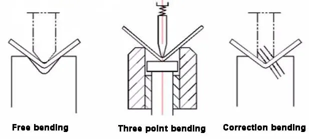
Free Bending
Free bending, also known as air bending, is less complex than other methods. The bending angle is controlled by the depth of the upper die into the V-groove of the lower die.
The accuracy of the bent parts depends on various factors, such as Y1, Y2, and the V-axis upper and lower molds and plates.
However, it is widely used due to its versatility and broad processing range. It is applied to structures with a simple structure, large volume, or not too large output.
Three-Point Bending
Three-point bending, also referred to as die bending (bottoming), has a bending angle that is determined by the wedge height in the lower die.
The upper die only provides enough bending force and eliminates non-parallelism between the dies through the hydraulic pad on the ram.
This method can produce parts with high precision, meaning small angle and straightness errors. It is used for structures with complex structures, small volume, and mass processing.
Correction Bending
Correction bending is formed in the cavity composed of upper and lower dies, allowing for an ideal section shape to be obtained. However, it requires a large bending force and repeated mold repairs, and has poor mold versatility.
This bending method is often used when there are special requirements or special section shapes that cannot be achieved by free bending.
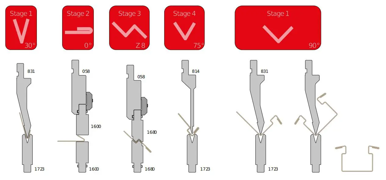
Stage Bending
Stage bending consists of fitting a press brake with different tools at the same time to speed up the bending process.
Stage bending is necessary when a profile has to be produced by using different tool sets; operators can move the sheet metal from one tool set to another along the Z axis of the press brake to make the different bends.
It is important that the operator:
- installs sets of punches and dies with exactly the same working height; it means that the total working height of all tool sets (punch height + die height)must be the same.
- In some workshops shims are placed under the dies to compensate for the small difference between two stations. In this instance, there is a risk of reducing the bracket clamping surface which then reduces the stability of the bottom tool;
- Sets the numeric control of the press brake indicating the position of each bend along the Z axis, in order for the back gauges to be in the right position for each bend.
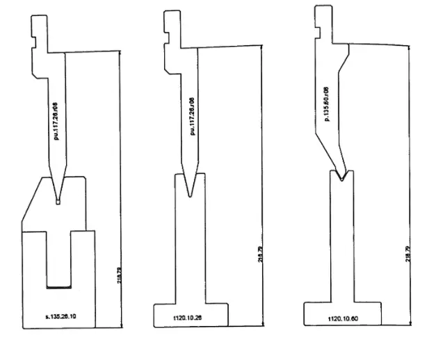
Large Radius Bend
Large-radius bends can be obtained by using radius tool holders, which can hold radius tools of different dimensions to get the required bending radius.
These radius tools are very useful for small and medium-sized press brakes, which have tables that are too small to mount the big dies necessary to obtain large radius bends.
During large-radius bending sheet metal yields less than during other types of bending, so springback is greater and difficult to calculate.
So a bend test needs to be carried out in order to determine the precise value of the springback, which is dependent on the material and its thickness, and the radius to be obtained.
Furthermore, bear in mind that springback influences the internal bending radius therefore the radius tool to be used must be smaller than the required internal bending radius.
The chart below estimates average springback and the punch tip needed to obtain different internal bending radi depending on the different sheet metal thicknesses:
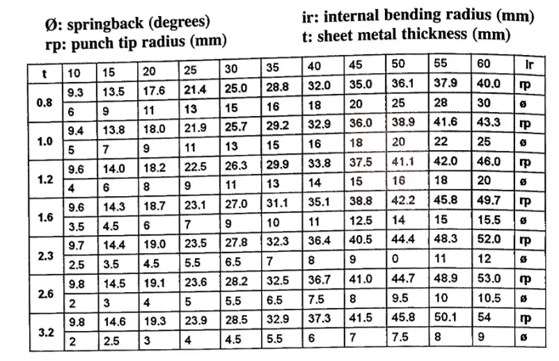
After determining the radius, another difficulty is to decide on the width of the vee die that will achieve the correct bend. In fact it is important to find the correct ratio between the two values.
The following formulas give an idea of the most suitable die to use:
- if the springback is < 5°, V=2.2(rp+t)
- if the springback is >5°, V=2.5(rp+t)
- V:die width in mm
- rp: punch tip radius in mm
- t: sheet metal thickness in mm
During large-radius bending, sheet metal may leave the area of contact with the radius tool and create an air bubble in the internal bending radius. This is known as premature bending. The result is therefore not very precise.
If you need a very precise internal radius, it is better to use dies with plastic inserts, which push the sheet metal against the radius tool thus avoiding premature bending .
If sectioned radius tools are needed, traditional holders with screw holes for attaching radius tools are not appropriate. In this case, operators must choose sectioned radius tools with a pass through screw that can also accommodate short radius tool segments.
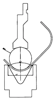
Another problem operators have to face during large-radius bends is that of understanding the drawing and of defining the distance between back gauges(x-axis) and the bending axis (y-axis).
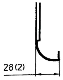
Press brake operators often obtain this dimension by carrying out tests with waste sheet metal until they get the required profile. We recommend that designers indicate in the drawings the dimension between the center of the curve and the point of contact of the sheet metal with the back gauges.
For example, in the drawing on the right the external 28mm dimension is useless to the press brake operator, who actually needs the dimension from the center of the curve to the point of contact of the sheet metal with the back gauges (side already bent), which is 25.2mm.
Bump Bending
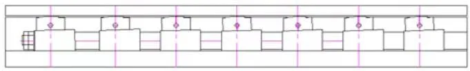
If the internal radius required is very big and cannot be obtained in one hit, operators may have to obtain it through bump forming. Bump forming consists of bending with several press brake hits to obtain a bend similar to roll bending.
Large-radius bends made by bump forming are aesthetically quite poor, as the radius is composed of a number of short straight sides which are clearly visible.
To use bump forming, a number of factors must be established. First of all the operator must calculate the number of press brake hits required
and then, in order to know the distance and angle between each bend, he must:
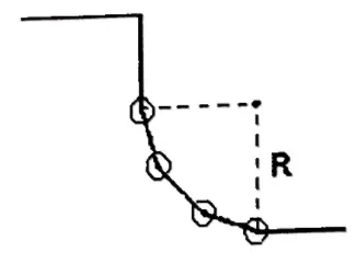
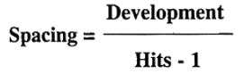
1. Calculate the development of the sheet metal:
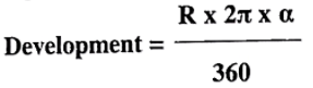
- R = internal radius required
- α = bending angle
2. Once the number of hits is defined, determine the spacing, i.e. the x dimension of each bend
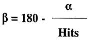
3. Once the number of hits is defined, calculate the angle of each bend
If an operator sets the numeric control of his press brake using these parameters, he will obtain the required radius and angle.
During this type of bending, an operator must check that the sheet metal
presses against the back gauges; if this is not possible, he must draw bending lines directly onto the sheet metal and bends along them without using backgauges.
How to Choose Press Brake Bending Axis?
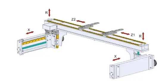
Y1 and Y2 Axis: Controls the movement of the ram up and down
V Axis: Controls the deflection compensation of the press brake
X, R, Z1, Z2, and X’ Axis: These are the control axis of the rear positioning system, responsible for controlling the positioning position of the rear stop (refer to the definition of each axis in the illustration)
T1 and T2 Axis: Servo material support (sheet follower). During the bending process, the processed plate follows the support, and the sheet followers provide support for the material.
The following axes are necessary for each press brake machine: Y1, Y2, and V. Users can select the rear stop and servo follow-up material support axes based on the needs of the processed parts.
It’s important to note that the X’ axis cannot be selected separately and must be used in conjunction with the Z1 and Z2 axes to have any practical significance.
V axis is the deflection compensation axis, and there are two implementation methods.
One is position control, which compensates for the elastic deflection deformation of the machine during bending by giving an equal amount of reverse deformation at its corresponding points based on the deflection deformation curve of the worktable during bending.
The other method is pressure control, which adjusts the pressure of multiple deflection compensation cylinders to generate a reaction force against the bending force at multiple points on the vertical plate of the workbench to prevent deflection deformation.
It’s generally agreed that position control results in higher bending accuracy and is used in 500T+ press brake machines. A schematic diagram of the worktable convex principle can be seen in the following figure.
The accuracy of the Y1, Y2, and V axes is crucial for the angle and straightness of the bent parts. It is important to note that for thin plates (<3mm), the accuracy of the bent parts is directly determined by the quality of the plate itself, such as the size of the thickness error, material uniformity, and rolling texture direction.
Bending Principle of Sheet Metal
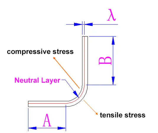
After V-shaped bending, the inner surface of the bending part of the workpiece experiences compression deformation, while the outer surface experiences tensile deformation.
The greatest deformation occurs at the surface of the material, and it decreases as the plate thickness deepens.
There is a neutral line, called the X-X line, that is neither compressed nor stretched.
To determine the position of the neutral layer, consider the following:
If the IR (inside radius) of the workpiece is 5 times greater than the plate thickness, the neutral layer is positioned in the center of the plate thickness.
If the IR of the workpiece is 5 times less than the plate thickness, the neutral layer position shifts towards the interior as the IR decreases, with the thickness of the bending position turning into t.
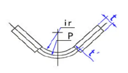
The relation between the radius of the neutral layer (represented by P) and IR can be described as follows:
- R≥5t, P-IR=0.5t
- R<5t, P-IR=(0.25-0.4)t
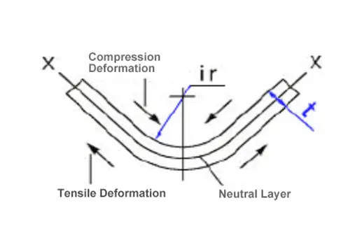
The neutral layer has the characteristic of being neither stretched nor compressed, so its length is used as the expanded length of the bent piece.
K-Factor and Neutral Axis
Press brake bending involves leveraging force to shape sheet metal into desired geometries. Two vital concepts in press brake bending are K-factor and the neutral axis. Understanding these elements is crucial for achieving precise and repeatable bending operations.
K-factor is a value representing the location of the neutral axis within the sheet metal during the bending process. The neutral axis experiences neither compression nor elongation while bending the sheet metal. With a range between 0 and 0.5, the K-factor varies according to the material and the bending process. Typically, the K-factor value falls around 0.33—indicating that the neutral axis is approximately one-third of the way into the material.
An accurate K-factor is essential in calculating bend deductions or bend allowances, ensuring the final dimensions of the bent part meet precise specifications. Several factors affect the K-factor, including the material type, thickness, grain direction, and the bending process itself. It is crucial to account for these variables to achieve accurate, consistent results in press brake bending operations.
The neutral axis is an imaginary line within the sheet metal where the material’s fibers experience no strain during the bending process. Positioned parallel to the bend axis, it separates the material into two zones—the inner section experiencing compression and the outer section experiencing tension. By understanding the neutral axis, operators can ensure better control over the resulting dimensions and material properties after bending.
In summary, K-factor and the neutral axis play vital roles in press brake bending operations. By accurately determining the K-factor and understanding the neutral axis, operators can achieve precise, consistent bends in sheet metal parts. It is crucial to consider material type, thickness, grain direction, and the bending process when applying these concepts to ensure optimal bending results.
Radii, Bend Deduction, and Springback
Press brake bending involves precise knowledge of key factors such as radii, bend deduction, and springback. Understanding these concepts will help in achieving accurate and consistent bends.
Radii refers to the various measurements of the bend radius, an essential factor in determining the outcome of a bend. The bend radius is the distance from the center of the bend to the inside of the material being bent. The inside bend radius is the distance from the innermost point of the bend to the initial position of the material. It is crucial to determine the appropriate radii to ensure a smooth bend and avoid stress or cracks in the material.
Bend deduction is another fundamental concept in press brake bending. The bend deduction refers to the difference in length between a straight piece of material and the bent piece. To calculate the bend deduction, one needs to consider the inside bend radius and the material thickness. Accurate bend deduction calculations are necessary for achieving consistent bends with desired bend angles.
Springback is the natural tendency of a material to return to its original shape after being bent. When the press brake applies force to bend a material, the elastic properties of the material cause it to spring back and reduce the bend angle. To counteract springback, the bend angle must be slightly over-bent to compensate for this effect. Different materials exhibit varying degrees of springback, making it crucial to consider this factor in the bending process.
Understanding and properly employing these concepts of radii, bend deduction, and springback will lead to successful press brake bending operations, resulting in accurate and consistent bends.
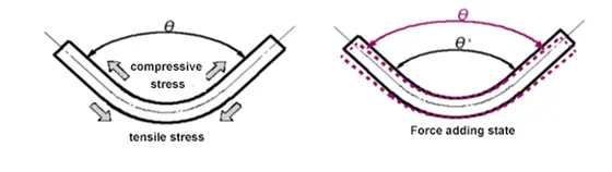
Reasons for Springback in Sheet Metal Bending
Bending is the deformation of a plate caused by both tensile and compressive stress on its front and back.
After being bent to the desired angle, the material will tend to return to its original shape once the pressure is released, resulting in a phenomenon known as bending springback.
This springback is usually expressed in terms of the angle it causes and is influenced by various factors such as the material, plate thickness, pressure, and bending radius.
Accurately calculating the amount of bending springback is challenging.
The force applied during bending and the counterforce it creates are different, and once the pressing force is removed, the angle will decrease due to the restoring rebound.
1) When using the same punch with the same thickness of material, the resilience value for SPCC is lower than AL and AL is lower than SUS.
2) When using the same punch with the same material, a thinner plate has more resilience.
3) When using the same material, the one with a larger IR has more resilience.
4) The greater the pressing force, the less resilience.
Most Commonly Used Bending Methods

| Bending Method | V-width | IR | Angle Accuracy | Features |
|---|---|---|---|---|
| Air Bending | 12T—15T | 2t~2.5t | >±45’ | Can achieve a wider range of bend angle. |
| Bottoming | 6T—12T | 1t~2t | ±15’—30’ | The higher bending precision is obtained with the smaller press force. |
| Coining | 5T(4T—6T) | 0t~0.5t | ±10’ | It can achieve high bending precision, but the bending force is very large. |
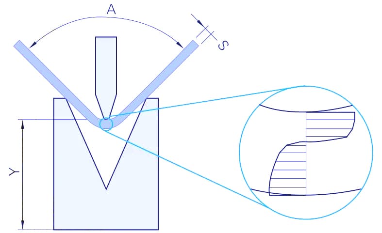
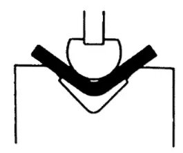
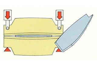
Air bending
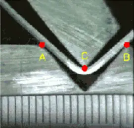
Air bending refers to a bending process where only a portion of the material comes into contact with the tooling.
As depicted in the image, the tooling only touches points A, B, and C on the metal during bending (the punch tip and die shoulders), while the rest of the material remains untouched.
As a result, the actual angle of the tooling becomes inconsequential. The bend angle is instead determined by the depth to which the punch descends into the die; the deeper the punch descends, the sharper the bend angle.
This means that fabricators can achieve a wide range of bend angles with just one set of tooling since the bend angle is controlled by the depth of the stroke rather than the tooling itself.
However, it is important to note that there will be some degree of spring back in air bending, so the desired bend angle can be achieved by bending the metal at a slightly sharper angle.
Features of air bending:
- Wide bending angle with one set of tooling. The angle can’t be smaller than the punch tip angle. If using a 30° punch, 180°-30° bending angle can be obtained.
- The bending need less press force.
- The bending angle is not in high accuracy.
- The material has more spring back.
See also:
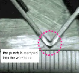
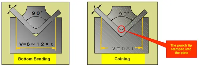
Bottoming

Bottoming” refers to a bending method in which the punch is pressed down to the bottom of the die, causing the material to make contact with both the punch tip and the sidewalls of the V-shaped opening.
This method allows for the production of parts with good bending precision while using less pressure, and is widely used in the industry.
V-opening width
The V-opening width of the die can refer to below table:
| T | 0.5-2.6 | 3-8 | 9-10 | ≥12 |
|---|---|---|---|---|
| V | 6T | 8T | 10T | 12T |
IR of workpiece
The interior radius of the workpiece is commonly denoted as IR.
In the bottom bending process, the IR is approximately 1/6 of the V-opening of the die (IR = v/6).
However, IR can vary for different materials such as SUS and Al, which have distinct IR values.
Tooling accuracy of bottom bending
The angle after bottom bending will be affected by the spring back, so the bending spring back will be considered when choosing bottom bending.
The usual solution to obtain the target angle is by overbending.
- Material, shape and thickness with small spring back – 90° tooling
- Material, shape and thickness with big spring back – 88° tooling
- Material, shape and thickness with bigger spring back – 84° tooling
When adopting bottom bending, the principle of using the same angle for both punches and dies should be abided by.
Coining
The term “coining” is derived from the coin-making process, which is known for its high accuracy.
In the coining process, a sufficient tonnage of the press brake is used to shape the sheet metal to the precise angle of the punch and die. The sheet metal is not only bent, but it is also compressed between the punch and die.
Coining is not only accurate, but it also results in a very small interior radius (IR) of the workpiece. The tonnage required for coining is 5-8 times higher than that required for bottom bending.
V-Opening Width
The V-opening width required for coining is smaller than that required for bottom bending and is typically 5 times the thickness of the sheet metal. This is done to reduce the IR of the workpiece and minimize the stamping of the workpiece’s IR position by the punch tip. By reducing the size of the V-opening, a higher surface pressure can be achieved.
Pressure Limit
Due to the high pressure involved in bending, the thickness of SPCC should not exceed 2mm and the thickness of SUS should not exceed 1.5mm. For example, 2mm SPCC material requires 1100KN of pressure for bending, which exceeds the 1000KN allowable pressure of some tooling. Note that different tooling has different allowable pressures, so not all tooling can be used to bend 2mm SPCC material.
Coining Problems
Due to the large bending force involved in coining, the tonnage of the press brake must be increased, which can lead to serious wear and tear on the tooling. Thus, only tooling with high allowable pressure can be used for coining.
Top Punch Selection
1. The selection of the top punch is determined by the workpiece shape.
In simpler terms, there should be no collision between the punch and the workpiece during the bending process.
To ensure that the punch and the workpiece do not interfere with each other, determining the proper bending sequence is crucial.
When selecting the top punch shape, a 1:1 figure or cross-section illustration of the top punch can be used.
2. The selection of punch tip R
The interior radius (IR) of the workpiece is determined by the V-opening of the lower die (IR = V/6), and the selection of the punch tip radius (R) is influenced by several factors.
The IR of the workpiece can be calculated using the formula IR = V/6, and the punch tip radius can be slightly smaller than the IR. However, in recent years, a 0.6R punch tip has been recommended for bending thin sheet metal because:
- Able to center the punch and die correctly
- The abrasion of the punch tip
3. The selection of punch tip angle
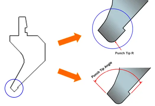
For the coining process, a 90° punch is used.
However, if the spring back of the workpiece is minimal when bending soft steel plate less than 2mm, a 90° punch can also be utilized.
For materials with a significant amount of spring back (such as SUS, Al or medium plate), the 88° punch, then the 84° punch, and finally the 82° punch can be selected based on the material’s level of spring back.
It is important to note that the angle of the die should match the angle of the punch tip.
Common Punch Tip Radii (R):
- 0.2R
- 0.6R
- 0.8R
- 1.5R
- 3.0R
Standard Punch Tip Angles include: 90°, 88°, 86°, 60°, 45°, 30°, etc.
For 90° bending, the commonly used punch tip angle is 88°.
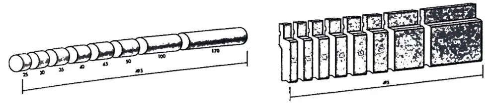
4. The segmentation of punch and die
- A-type segmentation: 100(left horn),10,15,20,40,50,200,300,100(right horn) = 835mm
- B-type segmentation: 100(left horn),10,15,20,40,50,165,300,100(right horn) = 800mm
Selection Principle of 88° Die and 90° Die
The tensile strength of the material
- High tensile strength – choose 88° die
- Low tensile strength – choose 90° die
The bending spring back amount
- Large amount of spring back – choose 88° die
- Small amount of spring back – choose 90° die
Coining method
- Choose 90° die
V-Opening Width Selection
- If using coining, please refer to the following table:
| T | 0.5-2.6 | 3-8 | 9-10 | ≥12 |
|---|---|---|---|---|
| V | 6T | 8T | 10T | 12T |
Confirm the minimum bending width (b) of the product and ensure that the selected V-opening meets this requirement (b=0.7V).
Note:
The smaller the V-opening, the higher the pressure required for bending will be.
If ir is not specified in the drawings, use the standard R value (R=thickness).
If ir is specified, select the V-opening strictly based on the specified ir (ir=V/6).
The selected V-opening may need to be larger or smaller than the target V-opening width depending on the conditions.
After determining the V-opening width, perform a bending force calculation.
Confirm the following for the calculated bending force:
- Whether it can meet the tonnage requirements of the press brake for bending fabrication?
- Whether to meet the tooling’s allowable tonnage?
Elongation of the Material
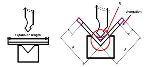
In the bending process, due to the compression on the inside and stretching on the outside of the material, there is a partial extension of the material, referred to as the elongation rate.
The formula for determining the elongation rate is A + B – expansion length.
The elongation rate of the material is not constant and is affected by various factors, including:
- Properties of materials (texture, plate thickness)
- Properties of toolings (V-opening width, punch tip R)
- Processing properties (bending angle)
The elongation rate of the material is now calculated by computers, with each manufacturer’s method being protected as patented technology and therefore not disclosed.
However, during actual processing, there may be deviations in the calculation of the elongation rate, so the most accurate measurement must be obtained through actual testing.
5 Properties Affect Bend Fabrication
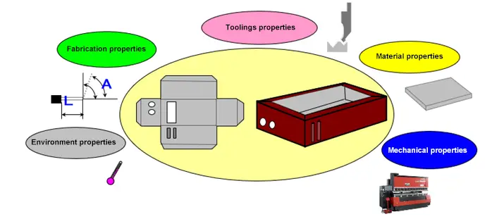
- Mechanical properties: what machine tools are used
- Material properties: what materials are used
- Toolings properties: what toolings are used
- Fabrication properties: what size and angles
- Environment properties: under what circumstances
V-Shape Bending Force Calculation
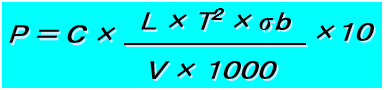
- P: bending force (KN/M)
- V: lower die V-opening width (mm)
- L: bending length (mm)
- T: plate thickness (mm)
- σb: tensile strength of the material (N/mm2)
- C: correction coefficient
C correction coefficient list:
| V | 5T | 6T | 8T | 10T | 12T | 16T |
|---|---|---|---|---|---|---|
| C | 1.45 | 1.4 | 1.33 | 1.28 | 1.24 | 1.2 |
﹡The above calculation formula of bending force is obtained through experiments.
You can also check this article to learn all the 3 ways to calculate the required bending force.
Allowable Tonnage of Toolings
Each tooling has a corresponding maximum allowable tonnage value. If the pressure applied during processing exceeds the tooling’s allowable value, it can result in deformation, bending, or even breakage of the tooling.
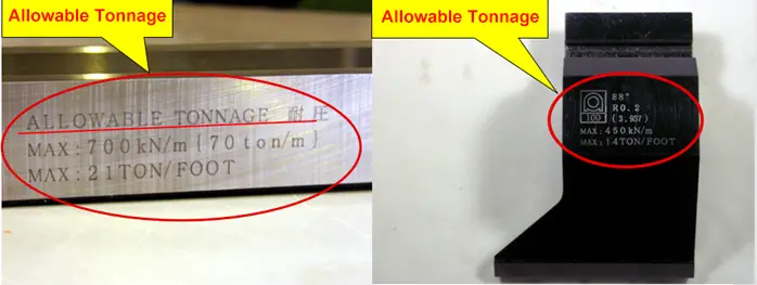
The allowable tonnage of the tooling is measured in kiloNewtons per meter and is calculated based on the length of the bend parts.
For example, if the product length is 200mm and the marking on the tooling is 1000KN/M, then the maximum bending force is calculated as follows:
1000KN/M x 0.2M = 200KN/M (20 ton)
Therefore, the maximum bending force should not exceed 20 tons.
Allowable tonnage calculation of punch

Let’s take the HRC47 material as an example:
The calculated maximum allowable tonnage (KN/M) can be determined using the formula: 9.42 x H^2/L x 10.
For example, if H = 15 and L = 30, the maximum allowable tonnage can be calculated as:
9.42 x (225/30) x 10 = 9.42 x 7.5 x 10 = 706.5 KN/M = 70 TON/M.
The allowable tonnage of punch will decrease under the following conditions
① Open avoidance slot, hole punch or some other additional works
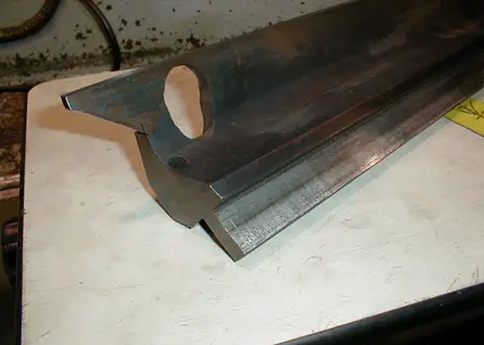
Open hole and slot at the horn
② When heating and hardness decrease

When using the grinding wheel cutting machine to make the horn, the hardness of the punch is decreased due to heat.
③ There’s a little bit of cracking
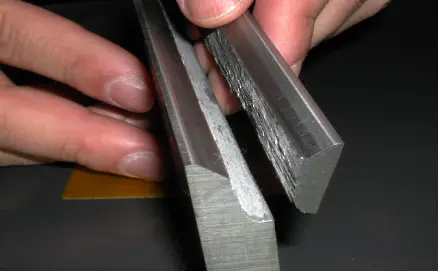
Continue to be used even there are tiny cracks
Selection of the Punch Height
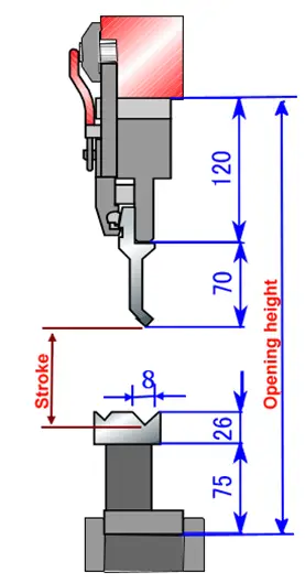
The stroke is calculated as follows:
Stroke = opening height – intermediate plate height – punch height – die base height – (die height – 0.5V+t)
For example:
opening height: 370mm
Max stroke: 100mm
Stroke (above fig.) = 370-120-70-75-(26-0.5*8+t) = (83-t) mm
Attention should be paid when selecting the tooling’s height:
0.5V< stroke < max stroke
Theoretical Calculation of Bending Expansion(90°)
During bending, the outer layer is subjected to tensile stress, while the inner layer is subjected to compressive stress. There is a transition layer known as the neutral layer that is neither subjected to tensile nor compressive stress.
This neutral layer remains the same length before and after the bending and serves as the benchmark for calculating the length of the bent part.
Common factors affecting bending coefficient:
- thickness
- material
- die width
- die tip R
- punch tip R
- material’s rolling
- others
Material’s Properties
1. The impact of plate thickness on the stroke
- If the thickness of the plate increases, the stroke of the bending angle will be decreased. (The thicker the plate, the smaller the V/t)
- The influence of plate thickness change on stroke change, SUS<SPCC<AL
- The impact of plate thickness on stroke increased:
(average plate thickness difference)< (nominal thickness) < (plate thickness changes)
2. The influence of material coefficient changes on the stroke
- The greater the V-opening width and thickness of the plate, the greater the influence of the material coefficient on the change of stroke.
(The larger the bending angle, the more susceptible to the change of coefficient)
- The influence of material coefficient change on the change of stroke, generally speaking.
AL < SPCC < SUS gradually increasing.
- The change reasons of the material coefficient are as follows:
Not the same coil < Material differences within the same manufacturer < Different manufacturers < Material handling is different, gradually increasing based on the condition.
How to Adjust the Parallelism of Bending Workpiece?
Regardless of whether you are a press brake operator or the head of the production department, it is important to understand the significance of parallelism in bending workpieces. I will outline 4 steps for adjusting the parallelism of bending workpieces for you.
1) Return the press brake ram to the starting position and reduce the pressure gauge value to the lowest value that just moves the ram.
2) Place two blocks of equal height on the table, ideally under the left and right cylinders.
3) Change the hydraulic sheet bending machine to the “jog adjustment” mode, remove the upper and lower molds and any other attachments, raise the mechanical block to its highest position, and disconnect the coupling on the mechanical block drive shaft gear.
4) Carefully place the ram onto the two blocks (the bottom face of the ram mold should touch the blocks).
Related Security Strategy
Press brake is a type of press machine.
When only producing one product, it is easy to maintain safety. However, when producing multiple products, even in small quantities, it becomes more difficult to control safety.
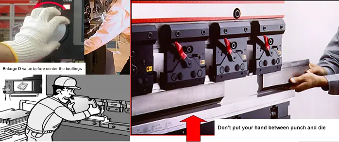
There are also safety measures to be taken during the bending process and when installing the die.
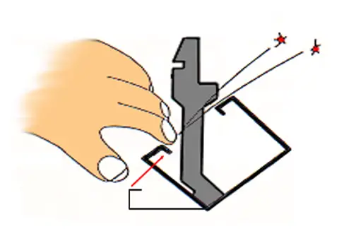
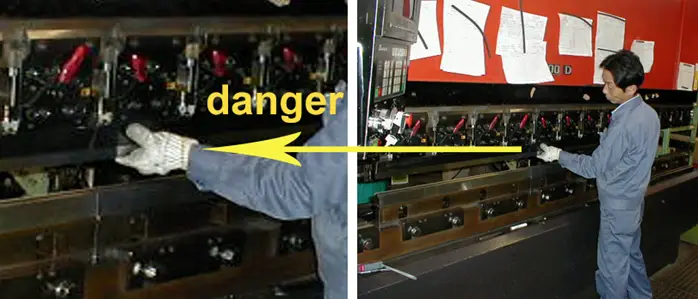
The same safety issues that arise in other tasks are also present in the bending process. For example, fingers can get caught in the punch and die or become sandwiched between the punch and the workpiece.
To prevent accidents, relying solely on light safety devices or fence-type safety devices is not enough. It is crucial to establish correct operating methods and raise operators’ safety awareness.
Safe operation
Confirm the toolings’ allowable tonnage

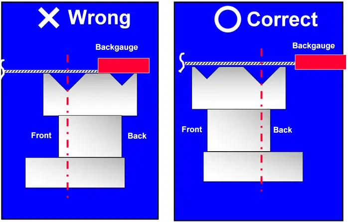
Confirm that the toolings’ center is consistent before the punch and die closure
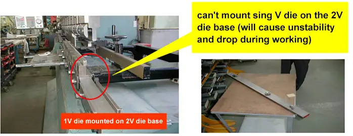
Proper use of 2V die
Select the correct punch
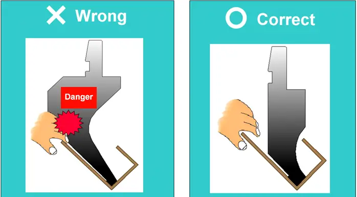
When taking apart the toolings, try to insert the punch into the lower die to prevent the punch from falling and hurting the finger.
Do not hang items on the emergency stop button
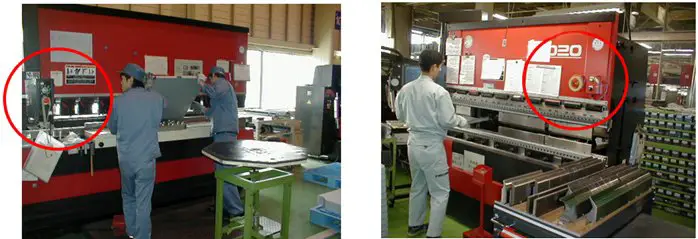
Incorrect tooling installation


Sir,
Thanks for sharing the information.
Could you please help me with formula for the movement of Punch (Down in MM) to achieve a particular angle.
Ex, if I know the thickness of Sheet, Height & Width of V-Die than How much should press punch(in mm) to get the required angle.
Please help!
You can use bending depth calculator here: http://www.machinemfg.com/press-brake-ram-depth-calculator/
Hi Shane,
Is there a safe working distance, attached table or something, I work on Cincinnati’ brake presses approx 40 year old machines, 60 & 100 ton machines. What determines the distance? Or is there one
Thank you
You can refer to the press brake safety guide from Amada:https://www.amada.co.jp/include_asean/products/bankin/pdf/saftyguide_bend_e.pdf