You can scroll directly to the bottom of the page to download the PDF version of the operation manual for the following press brake control systems: Estun E21, E200P, E200+, CybTouch 8, CybTouch 12, Esa S630, Delem DA41, DA52S, DA53T, DA58T, DA66T, DA69T.
Introduction!
We strongly recommend that all users and operators read this press brake operation manual thoroughly before using the press brake machine.
This manual is intended for specialized and qualified personnel and comes with diagrams and all the necessary documentation to lift, move, and place the machine, as well as instructions for safe use and maintenance.
Please note that all information contained in this manual is accurate at the time of printing. However, our company reserves the right to modify and improve specifications without prior notice.
To ensure proper performance, it is important to install the press brake as instructed and to conduct regular inspections and maintenance services. Any incorrect or irresponsible usage can result in irreparable damage to the machine and compromise the safety of the operator.
We are not responsible for any improper services, modifications, or connections made by unauthorized personnel.
Further Reading:
- Electro-Hydraulic Servo Press Brake Operation Manual
- Press Brake: The Ultimate Guide
- Press Brake Bending Basics: The Definitive Guide to Sheet Metal Bending
Press Brake Functions and Range of Work
1.1 This press brake is high-efficiency and high-precision in bending metal sheet.
The opening size of the V-groove on lower dies is typically 8 times greater than the thickness of the sheet, and it should be adjusted for sheets of varying thickness.
Different types of upper and lower dies can be used to bend a variety of workpieces (refer to Fig. 1).
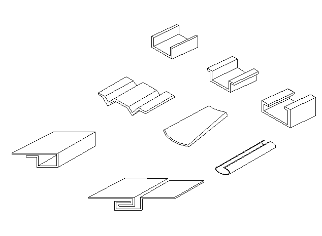
Fig.1
1.2 The press brake is structured in steel plate fabrication with sufficient strength and rigidity.
The hydraulic drive of the machine prevents serious overload operation accidents due to changes in sheet thickness or incorrect selection of the lower die cavity. This machine also offers stable performance, ease of operation, and reliable safety.
The connection to the upper die is equipped with a compensation device, which compensates for deflection of the worktable and slider during bending, ensuring high precision.
The mechanical block is equipped with an oil cylinder to ensure accurate fixing when the slider reaches the bottom dead point and maintain consistency in bulk production.
1.3 It is equipped with hydraulic and electric control, allowing for the slider’s travel to be freely adjusted and making it convenient for trial and adjustment with an inch operating criterion.
1.4 This press brake is technologically advanced and boasts dependable performance, making it one of the ideal shaping devices.
It is widely used in the industries of aviation, automobile, shipbuilding, and machinery, due to its high production efficiency.
1.5 Operation condition:
- Temperature: 5~38℃(Working temperature)
- Environment moisture: Relative moisture 20~80%RH。
- Keep far away from powerful vibration and electromagnetic interference.
- No pernicious and corrosiveness gas, and no dust.
Installation of press brake
Lifting
It is imperative to ensure that when lifting the press brake for transportation or positioning, it must be done with a crane that has sufficient lifting capacity to avoid the risk of the press brake falling.
Two steel rope slings and shackles should be used, utilizing the appropriate holes located at the top of the machine.
The steel rope must be of adequate size to lift the weight of the press brake and of a sufficient length, as its weight-carrying capacity decreases as the angle between the ropes widens (refer to Fig. 2).
Fig.2
Transport
When transporting the press brake, keep in mind that the majority of its weight is concentrated in the front. Ensure that the top ram is fully lowered for any movements or transportation. When loading the press brake onto a truck, position the rear of the machine as close as possible to the side of the vehicle. Secure the press brake to the truck using steel ropes.
Installation
The foundation of press brake
To ensure proper operation of the press brake machine and prevent disturbances caused by vibrations, it is important to verify that the surface it will be placed on is firm and stable.
If necessary, a concrete foundation that is suitable for the specific ground conditions should be prepared.
The detailed foundation drawing is provided as follows:
Make sure that there is adequate space around the machine once it is positioned. This is necessary to accommodate maintenance work and special tasks.
Additionally, sufficient space on either the left or right side of the press brake, equal to the length of the machine, must be available to facilitate tool changing operations.
All exposed surfaces of the machine are coated with rust guard, which can be easily removed with kerosene or solvent.
Leveling
To ensure correct operation of the press brake, it is necessary to properly level the machine. To check horizontal leveling, place a spirit level on the machine table.
For vertical leveling, place the spirit level on the machine table again. Any necessary adjustments can be made by adjusting the leveling bolts located in the feet of the press brake.
The electrical diagram of the press brake
Here are the drawings:
3.1 The following steps must be carried out by specialized personnel and must be taken care of by the owner.
- Check the nameplate of the machine and ensure that the wiring of the press brake is in good condition.
- Connect the press brake to the available power source in your facility.
- If the required power does not meet the requirements of the machine, please contact your electrical supplier.
- Ensure that the power incoming to the press brake machine is fused, so the machine can be fully disconnected for repair if necessary.
- Connect the power incoming to the press brake machine to the RST clamps in the control cabinet.
- The electrical drawings can be checked using the attached documents, as different controllers have different drawings.
Here are the drawings:
Detail description is as follows:
To operate the press brake machine, follow these steps:
- Connect the three-phase power lines to the inlet terminals in the electric box. Then, plug in the feet switch socket located under the box, and close the power switch QF and the door of the electric box. The lighting of lamp HL1 indicates that the machine is powered on.
- Start the oil pump motor button HL2 on the operation panel for a short time and observe the direction of the motor. If the direction is incorrect, change the phase of the inlet lines but never change the internal lines inside the electric box. Then, start the oil pump motor again.
- In jog mode, after several minutes of normal operation, turn SA2 to the jog mode, step on the foot switch “up”. The ram will go up and when you loosen the foot switch, the slider will stop. To raise the ram further, continue to step on the foot switch until it reaches the limit switch SQ1 and stops. To lower the ram, step “down”. The ram will drop quickly and then, due to the effect of limit switch SQ2, the ram will go down slowly to add pressure. When you loosen the foot switch, the ram will stop.
- In single travel mode, turn SA2 to “single time”, then step on the “down” of the foot switch. The ram will go down first quickly, then slowly with pressure keeping, and finally, the ram will automatically go up to the upper limit switch SQ1. To adjust the working time of time relay KT1, make sure it meets the bending pressure requirements on the workpiece. Also, adjust the pressure-keeping time of time relay KT2.
- In continuity mode, turn SA2 to “continuity” and step on the foot switch for repeating the single travel mode. You can adjust the waiting time of circulation using time relay KT1.
Note: The above steps should be carried out by specialized personnel. To ensure safety, press brake machines with CE certification do not have a continuity mode.
The hydraulic system of press brake
Clean the hydraulic oil
To guarantee the quality of the hydraulic system, it is important to maintain the cleanliness of the hydraulic oil. Cleaning the oil tank is crucial.
When changing the hydraulic oil, it is necessary to remove the cover of the tank.
Wipe the bottom of the tank with a clean towel (do not use cotton), and then wash it with cleaning gasoline.
Due to the limited reach of the arm, the corners of the tank may be difficult to clean. Wrap a towel around a stick or bamboo to wipe these areas.
Loosen the leaking plug or brake valve to drain the dirty oil.
Dry the sides and bottom of the tank with a clean towel until they are completely clean.
If necessary, use a tool like a rolling pin to remove any dirt that may have accumulated at the welding seams or in hard-to-reach areas, and then replace the cover.
Choose the hydraulic oil
The mark value of hydraulic oil corresponds to its average viscosity at a temperature of 40°C.
If the hydraulic system experiences higher working pressure and temperature, and slower working speeds, a higher grade hydraulic oil should be chosen.
It is recommended to use antiwear hydraulic oil ISO VG46#, which has an average viscosity of 46mm2/s at a temperature of 40°C.
If the machine will operate at temperatures below 5°C for an extended period, ISO VG32# hydraulic oil can be used.
It is not advisable to operate the machine at very low temperatures (below -5°C), but if it does occur, allow the machine to idle for a while. An oil heater may be added to the circuit if necessary.
Under normal working conditions, the oil temperature should not exceed 70°C. If necessary, an oil cooler can be installed for special conditions.
Fill the oil
The oil used must be clean. Tighten the nut of the air filter and fill it through the filter. If you are using a filling equipment with a filter, you can open the cover of the oil tank and fill it directly.
Observe the oil gauge, and when the ram stops at the Top Dead Spot, the hydraulic oil should fill about 80% to 90% of the inner space.
Make the machine work by idling first and then at the maximum stroke to remove any air bubbles in the hydraulic circuit.
Hydraulic Diagram
Here are the drawings:
Standard control equipment
| 5.1 | Start button | To start the main motor running and Control circuit. |
|---|---|---|
| 5.2 | Stop button | To stop the main motor running and Control circuit. |
| 5.3 | Auto/Manual Mode Selector Switch | Select the working mode |
| In the Auto mode | -The ram will rise automatically when Preset pressure is reached and the dwell time is up. | |
| In the Manual mode | -Lowering and rising of the ram is by pressing the foot pedal. | |
| 5.4 | Foot pedal | Push and hold to command lowering the ram to reach bending point, release when the ram is moving up in AUTO mode. |
| Press to command lowering the ram and press to command raising the ram in Manual mode. |
Starting the press brake machine
Prior to starting the machine, make sure to perform the following checks:
- Clean and grease the guideways.
- Inspect the hydraulic system for any leaks.
- Check the oil level on the level gauge at the side of the tank with the top ram in the fully raised position. Top up the oil if necessary.
- Check the direction of rotation of the motor by observing the direction of the cooling fan. The fan should rotate clockwise, or in the direction of the arrow. If this is not the case, switch two wires in the supply line, but be sure to make the motor run by inching while doing so.
Turn the machine on
- Turn on the main switch.
- Switch the selector to auto.
- Turn on the main motor by pressing the green button.
Turn the machine off
The press brake must always be turned off when left unused for a few hours. When turning off, do the following:
- Select manual mode.
- Descend the ram by pressing the down pedal to make the top tool close to the V-die as possible.
- Press the stop button.
- Turn off the main switch.
Upper and lower tool setting
(Check out the drawings of press brake toolings)
Before beginning any bending, make sure that the upper tool and the selected V-opening are aligned to ensure a good outcome. Also, ensure that the V-die base and table surfaces are clean before proceeding with the steps.
- Lower the system pressure by turning the pressure-regulating knob counterclockwise.
- Set the mechanical depth stop to the lowest position, either manually or electrically.
- Select the MANUAL MODE and press the down pedal to lower the ram until the top tool is as close to the V-die as possible.
- Align the upper and lower tool by adjusting the V-die tightening bolts.
- After the alignment is correct, tighten all the V-die tightening bolts securely.
- Raise the ram by pressing the UP pedal.
We advise the following:
- Regularly check the fixing bolts of the tool clamp.
- Store the tool on a rack near the press brake to prevent damage to the top tool.
- Remember that each tool has a maximum capacity force.
Tools Change Procedure
÷TOP TOOL
When the top tool needs to be changed, do the following:
- Turn the mode selector to manual.
- Lower the ram as near to the V-die as possible.
- Turn the machine off.
- Loosen all the fixing bolts of the tool clamp.
- Remove the tool from the side of the machine.
- Mount the new top tool by sliding it in from the same side.
- Tighten all the fixing bolts of the tool clamp.
- Turn the machine on and check that the mode selector is on manual.
Lower the ram to seat the top tool in the V-die while reducing the system pressure by turning the pressure-regulating knob counterclockwise to prevent damage to the tool.
÷LOWER TOOL
To change a different V-die on your multi-V-die setup, follow these steps:
- Unscrew all the tightening bolts to free the V-die.
- Change the mode selector to manual.
- Turn on the machine.
- Lower the ram as close to the V-die as possible.
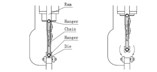
- Hook the V-die onto the ram at both ends using the appropriate chains.
- Raise the ram by stepping on the UP pedal to a height where the V-die can turn.
- Turn the desired V-die to face up.
- Lower the ram by stepping on the DOWN pedal so that the die rests on the machine table and the chains can be unhooked.
- Center the V-die with respect to the top tool.
- Lock the V-die in place by tightening the bolts.
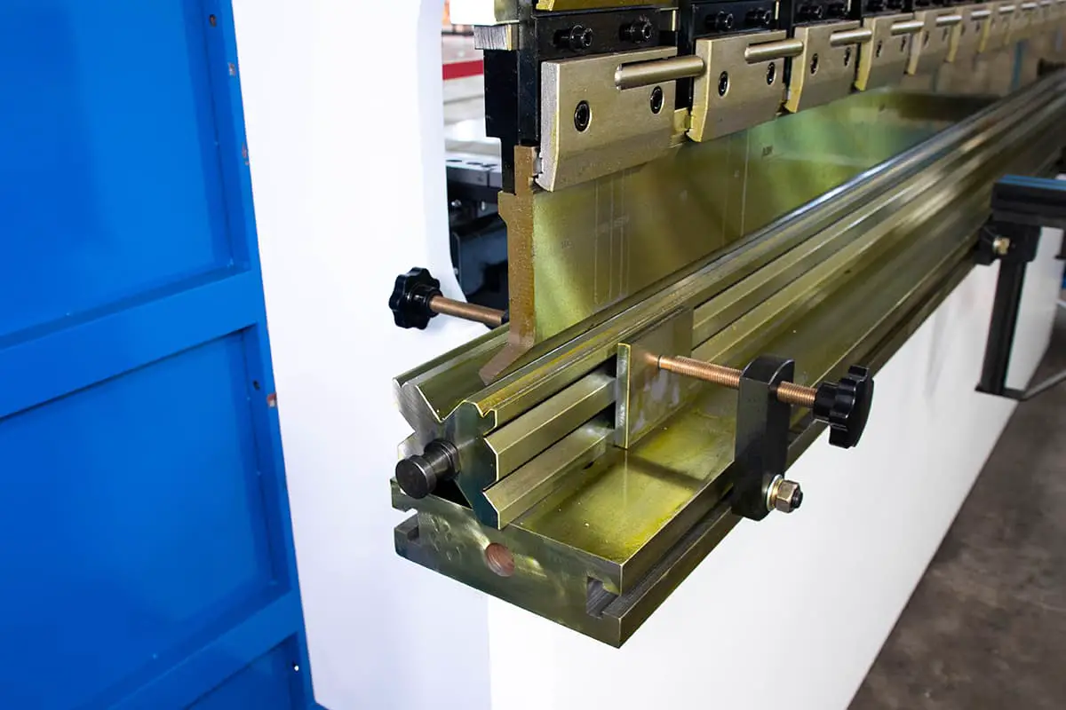
÷FRONT SUPPORT ARM
The press brake comes standard with two front support arms. These support arms are used to hold the plate in place during the bending process. They can be adjusted vertically and along the length of the press brake.
The support arms usually need to be adjusted when using a different size bottom tool or bending a larger or smaller size plate.
DANGEROUS!
If the punch and die are not placed correctly, do not start the machine at any time. Also, do not insert your hands or any part of your body into the space between the punch and die as it is extremely dangerous.
Mechanical depths stop setting
Do not attempt to adjust the mechanical depth stop setting when the ram is in the down position, as this can cause unnecessary damage to the machine.
- The depth setting determines the bending angle.
- The mechanical depth stop could be set either manually or electrically.
Pressure Setting
Normally the bending chart is fixed on the side of the machine, a copy is enclosed. The bending force is the function of :
- The plate thickness
- The width of the die opening. ( 8 x plate thickness )
The required bending force can be calculated from Table 1 formulate.
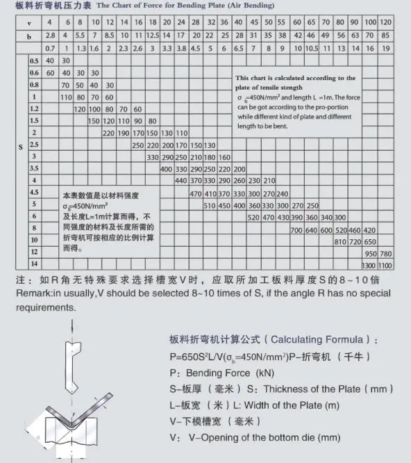
Note: This formula and the values in the table are based on carbon-steel plates with a tensile strength of Qb=450KN.
For stainless steel plates, multiply the P value from the table by 2.
For aluminum plates, multiply the P value from the table by 0.7.
You can also calculate the press brake bending force using our specially designed tonnage calculator for press brakes.
Parallelism control and setting
The parallelism of the ram is controlled by a solid anti-torsion bar that is linked to both side oil cylinders.
The top ram is calibrated parallel to the V-die at the factory, but if re-calibration is necessary, please follow these steps:
- Locate the torsion bar linkage connected to the top ram on the rear (left side) of the machine.
- Loosen the screw (M8/M10) on the torsion bar.
- Use the appropriate spanners to turn the outer flat piece by 15° to 30° in either a clockwise or anti-clockwise direction, which will rotate the eccentric pin inside.
- Tighten the screw (M8/M10) and check the parallelism of the top ram through a test bend.
- Repeat the procedure until the desired accuracy is achieved.
Press Brake Troubleshooting
Press Brake Machine cannot start
- Check incoming power supply.
- Check that Emergency Stop is release.
- Check for broken fuses.
- Check transformer output.
Ram could not be lower
- Check foot pedal cable for the possible broken wire.
- Check that limit switch.
- Check that motor rotation incorrect.
- Check that micro-switch inside foot pedal is working.
Bending angle not even on entire bend length
- Worn off upper tool or lower tool.
- Machine table surface and the underside of the V-die is dirty.
Top and bottom tools not properly aligned.
| Failure | Reasons | Trouble removal |
|---|---|---|
| The system doesn’t work without pressure | 1. Negative rotation of the motor | Change the rotation direction of the motor |
| 2. Main overflow valve blocked | Clean main overflow valve | |
| 3. Electromagnetic valve does not work | Check electric and electromagnetic coils | |
| Ram Slider cannot rise | Valves jammed | Clean electromagnetic valves |
| Slider declines automatically | Valves jammed | Clean electromagnetic valves |
| Normal rising and dropping but there’s no force in bending | Valves jammed | Clean electromagnetic valve |
| Leaking in components, pipe fittings and oil cylinder | Sealing pieces are aging. | Change sealing rings |
Maintenance of press brake
Anyone who operates and maintains this press brake must thoroughly read and understand this manual. Only by strictly following the instructions can optimal results be achieved.
A designated person should be assigned to the machine and the operators must have a working knowledge of the machine’s operation and safety in production.
The bending force applied to the workpiece must not exceed the nominal force. To extend the lifespan of the molds, it’s important not to damage them due to improper bending width, especially when bending narrow sheets. In these cases, the working pressure should be reduced appropriately. For every 630mm length, the bending load should not exceed 400KN.
The sheets being bent should be centered on the machine and should not be loaded unevenly, as this can compromise the accuracy of both the workpieces and the machine. If a workpiece must be bent on one side only, the load should not exceed one quarter of the nominal force, and the bending should be performed on both sides.
The hydraulic oil in the tank must be changed after the first month of use and then changed again within the year. The oil should be kept at a temperature between 15-60℃ (if the temperature is too high, a cooler should be installed).
This press brake machine requires periodic lubrication, which should be performed according to the working conditions and at all the designated lubrication points.
The user must have maintenance accessories on hand at all times.
After any heavy repairs, the machine’s precision must meet the factory standards.
Hydraulic oil
Check the oil level in the tank regularly.
Change the oil for the first time after 500 working hours, and then every 2000 working hours.
Use oil that meets the characteristics of the specified oil type.
The mark value of hydraulic oil is equal to the average viscosity when the temperature is 40°C.
If the working pressure and temperature of the hydraulic system are higher, and the working speed is slower, choose a higher mark hydraulic oil.
It is also recommended not to use the machine at very low temperatures (below -5°C), but if this occurs, let the machine run idle for a while. A oil heater can be installed in the circuit if necessary.
Under normal working conditions, the oil temperature must not exceed 70°C. Under special conditions, an oil cooler may be required.
It is recommended to use antiwear hydraulic oil ISO VG46# (with an average viscosity of 46mm2/s at 40°C). If the machine operates below 5°C for an extended period, you can choose hydraulic oil ISO VG32#.
Refill or replace only with the same grade of oil as follows:
- FIAT-HTF 46, ENERGOL HLP 46, ESSO NUTO H46, SHELL-TELLUS S46, TOTAL-AZOLLA 46
Oil Filter
- Regularly clean the oil filter by rinsing and brushing in a solvent.
- The oil filter should be changed when cleaning is not possible or damage.
- Use the same grade of oil filter when replacement is necessary.
Lubrication
Check the lubrication points regularly, and lubricate them with high-quality grease on a weekly basis. For parts that are exposed to wear and do not have lubrication points, they should be lubricated twice a week. (For more information, refer to the lubrication diagram.)
Electrical terminal
Regularly inspect all connections in the main panel and electrical switches, and tighten screws as necessary. Replace any faulty fuses and signal lights.
Mechanical parts
It is recommended to check at least once a month the following:
- Torsion bar bearing is properly secure
- Slides are not worn off
- Cylinders rod are properly secure
- The top ram is properly secure
Safety Ensuring and press brake machine main construction
Note:
This section applies to the press brake machine with specific requirements and is for reference only for other machines.
To ensure the safety of personnel and equipment, safety equipment has been designed. The operator must not alter, remove, or disable the safety equipment.
Light Beam/Laser Beam
The machine is equipped with a light beam or laser (as per customer request). If the operator interferes with the light curtain, the safety module will activate.
The ram will not be able to move downwards, preventing the operator from being injured.
Safety Grid
The machine has a safety grid at the side and back.
This grid keeps the operator away from hazardous areas and is connected to the electrical system by a safety switch. When the safety grid is opened, the electrical system is activated, and the machine cannot operate.
Emergency Stop
There is an emergency stop button located at the handle control station and hanging control station.
In case of an error in operation or any other accident, pushing the emergency stop button will cause the machine to stop all actions.
Hydraulic System
The falling of the ram is extremely dangerous. To prevent this, the system is equipped with a safety lifting valve.
The valve cores of the exchange valve and safety lifting valve have a monitoring signal.
If the valve core is abnormal, the monitoring signal will stop the electrical system to avoid injury from the falling of the ram.
If the valve cores of the exchange valve and safety lifting valve cannot be reset, inspect the valve.
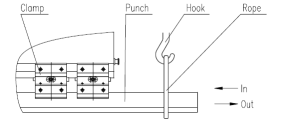
Troubleshooting
Normal operation is safe.
In case of any unusual accidents, or during maintenance or repair of the machine, lock the safety grid, push the emergency stop button located inside the uprights, and seek help.
If your hands or any other body parts are clamped by the punch or sheet, push the emergency button, inspect the situation, then restart the machine.
Switch the operating mode to the “inch” position.
Then, push the handle return button, and the ram will return, pulling out the clamped parts.
Overall drawings of press brake
Here are the drawings:
| Part No. | Name | Quantity |
| 1 | Control panel | 1 |
| 2 | Bearing block | 2 |
| 3 | Torsion bar | 1 |
| 4 | Pendulum pole | 2 |
| 5 | Cylinder base block | 2 |
| 6 | Connect pole | 4 |
| 7 | Oil cylinder | 2 |
| 8 | Guide rail | 2 |
| 9 | Cylinder cover | 1 |
| 10 | Single Control Valve | 1 |
| 11 | Pipe connector | 1 set |
| 12 | Pipe | 1 set |
| 13 | Oil tank | 1 |
| 14 | Manometer box | 1 |
| 15 | Coupling | 1 |
| 16 | Gear Pump | 1 |
| 17 | Main motor | 1 |
| 18 | Level Gauge | 1 |
| 19 | Filter 4-50 | 1 |
| 20 | Filter 250 | 1 |
| 21 | Close valve | 1 |
| 22 | FWMBM | 1set |
| 23 | Saddle of travel switch | 1 |
| 24 | Travel switch | 2 |
| 25 | Pole of travel switch | 1 |
| 26 | Connecting plates | 16 sets |
| 27 | Lower die | 1 |
| 28 | Upper punch | 1 set |
| 29 | Press plate | 52 |
| 30 | Star handle | 4 |
| 31 | Motor of back gauge | 1 |
| 32 | Ball screw | 2 |
| 33 | Guide rail | 2 |
| 34 | Stop beam | 1 |
| 35 | Stop finger | 2 sets |
| 36 | Foundation screw | 4 |
| 37 | Controller system | 1 set |
| 38 | Electric system | 1 set |
| 39 | Valve system | 1 set |
Download the PDF File of the Installation & Operation Manual:
- ESA S630 Installation & Operation Manual
- Estun E21 Installation & Operation Manual
- Estun E200+ Installation & Operation Manual
- Estun E200P Installation & Operation Manual
- CybTouch 8 Installation & Operation Manual
- CybTouch 12 Installation & Operation Manual
- Delem DA41 Installation & Operation Manual
- Delem DA52S Installation & Operation Manual
- Delem DA53T Installation & Operation Manual
- Delem DA56 Installation & Operation Manual
- Delem DA58T Installation & Operation Manual
- Delem DA66T Installation & Operation Manual
- Delem DA69T Installation & Operation Manual


I have a model – MPF 10 – 175 serial – CHPB 9 – 70133 – T im change the oil it said to change filter through a access hole all I see is were the pump is, is that the hole there talking about
The whole oil change process is mainly completed through the oil tank, which has nothing to do with the oil pump. Firstly, drain the hydraulic oil through the oil outlet, then clean the oil tank with gasoline or diluent, and finally inject new oil (above the filter screen) through the oil inlet.
Hellow Good evening, can I help me