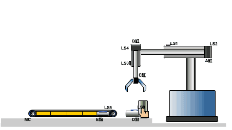
As is widely recognized, the progress of industrial production and the advancement of science and technology are closely tied to the use of Programmable Logic Controllers (PLCs) for automation.
PLC can be broadly understood as:
Centralized Control Cabinet for Relay Extensions.
In practical industrial applications, the use of a Programmable Logic Controller (PLC) significantly reduces control costs while enhancing centralized management and automation of equipment.
To gain a thorough understanding of PLC, it is essential to first establish a solid foundation in the technology.

1.From the composition of PLC, in addition to CPU, memory and communication interface, what other interfaces are directly related to the industrial site? And explain its main functions.
1) Input interface:
Receive the signal of the controlled equipment, and drive the internal circuit to turn on or off through the optocoupler and input circuit.
2) Output interface:
The execution result of the program is output through the optocoupler and output components (relay, thyristor and transistor) of the output interface to control the on or off of the external load.
2. Which parts does the basic unit of PLC consist of? What role does each play?
1)CPU:
The core component of PLC, which commands PLC to carry out various work.
Such as receiving user programs and data, diagnosis, executing programs, etc;
2) Memory:
Storage system and user programs and data;
3) I / O interface:
The connecting part between PLC and the controlled object in the industrial production site is used to receive the signal of the controlled equipment and output the execution result of the program;
4) Communication interface:
Exchange information with monitor, printer and other equipment through communication interface;
5) Power supply.

3.What are the types of PLC switch output interfaces? What are the characteristics of each?
Thyristor output type:
Generally, it can only carry AC load, with fast response speed and high action frequency;
Transistor output type:
Generally, it can only carry DC load, with fast response speed and high action frequency;
Relay output type:
Generally, it can carry AC and DC loads, but its response time is long and its action frequency is low.
4. According to the structure type, what types can PLC be divided into? What are the characteristics of each?
1) Integral:
CPU, power supply and I / O components are all concentrated in one chassis, which has compact structure and low price. Generally, small PLC adopts this structure;
2) Modular:
Each part of the PLC is divided into several separate modules, and different modules can be selected according to the needs to form a system. It has the characteristics of flexible configuration, convenient expansion and maintenance. Generally, this structure is adopted for medium and large PLC.
Modular PLC is composed of frame or base plate and various modules, which are installed on the socket of frame or base plate.
3) Stack type:
Combined with the characteristics of integral and modular, the CPU, power supply and I / O interface of stacked PLC are also independent modules, but they are connected by cables, which makes the system not only flexible configuration but also small volume.
5. What is the scanning cycle of PLC? What is its main influence?
The scanning process of PLC includes five stages: internal processing, communication service, input processing, program execution and output processing.
The time required for scanning in these five stages is called scanning cycle.
The scanning cycle is related to the running speed of CPU, PLC hardware configuration and the length of user program.
6. How does the PLC execute the user program? What are the stages of user program execution?
PLC executes the user program by means of cyclic scanning.
The execution process of the user program includes input sampling stage, program execution stage and output refresh stage.

Schematic diagram of button switch structure
1. Button cap
2. Return spring
3. Moving contact
4. Normally closed static contact
5. Normally open static contact
7. What are the advantages of PLC control system compared with relay control system?
1) Control method:
PLC adopts program mode to realize control, which is easy to change or increase control requirements, and the contact of PLC is unlimited;
2) Working mode:
PLC adopts serial working mode to improve the anti-interference ability of the system;
3) Control speed:
The contact of PLC is actually a trigger, and the execution time of instructions is on the microsecond level;
4) Timing and counting:
PLC uses semiconductor integrated circuit as timer, clock pulse is provided by crystal oscillator, with high delay precision and wide range.
PLC has counting function that relay system does not have;
5) Reliability and Maintainability:
PLC adopts microelectronic technology with high reliability, and its self inspection function can be found out in time.
8. Why does PLC produce output response lag? How to improve I / O response speed?
PLC adopts a circular scanning mode with centralized sampling and centralized output. This means that the state of the input can only be read during the input sampling stage of each scanning cycle, and the program execution result can only be sent out during the output refresh stage.
Additionally, the input and output delay of the PLC, along with the length of the user program, can cause a lag in output response.
To enhance the I/O response, there are several options available, including direct input sampling, output refresh, interrupt input and output, and intelligent I/O interface.
9. What are the internal soft relays of Siemens series PLC?
Input relay, output relay, auxiliary relay, status register, timer, counter and data register.
10. How to select PLC?
1) Model selection:
The structural form, installation mode, functional requirements, response speed, reliability requirements, model unification and other aspects shall be considered;
2) Capacity selection:
I / O points and user storage capacity should be considered;
3) I / O module selection:
Including the selection of switching value and analog I / O module, as well as the selection of special function module;
4) Selection of power module, programmer and other equipment.
11. Briefly describes the characteristics of PLC centralized sampling and centralized output working mode, and what are the advantages and disadvantages of this working mode?
Centralized sampling:
In a scanning cycle, the sampling of the input state is only carried out in the input sampling stage. When entering the program execution stage, the input end will be blocked.
Centralized output:
During a scanning cycle, the output related state in the output image register is only transferred to the output latch during the output refresh stage to update the output interface. The output state is always preserved in the output image register during other stages.
While this operational mode can enhance the system’s reliability and anti-interference ability, it may also result in a delay in the PLC input/output response.
12. What kind of working mode does PLC adopt? What are the characteristics?
PLC adopts the working mode of centralized sampling, centralized output and cyclic scanning.
Characteristic:
Centralized sampling refers to the process where, during a scanning cycle, the PLC samples the input state only in the input sampling stage. Once it enters the program execution stage, the input end becomes blocked.
Centralized output, on the other hand, involves the PLC transferring the output-related state in the output image register to the output latch only in the output refresh stage. This refreshes the output interface, and the output state is saved in the output image register during other stages.
Cyclic scanning refers to the process where the PLC needs to perform multiple operations in a scanning cycle. This is achieved through the method of time-sharing scanning, where the operations are executed one by one in order and repeated again and again.
13. What are the main parts of the electromagnetic contactor? Briefly describe the working principle of electromagnetic contactor.
An electromagnetic contactor typically consists of several components, including an electromagnetic mechanism, contacts, an arc extinguishing device, a release spring mechanism, support, and base.
The contactor works according to the electromagnetic principle:
When an electromagnetic coil is energized, the current passing through it generates a magnetic field. This magnetic field causes the stationary iron core to generate electromagnetic attraction, which pulls the armature towards it. As a result, the contact action is driven, and the normally closed contact is opened while the normally open contact is closed.
These two actions are interdependent.
When the coil is no longer energized, the electromagnetic force ceases to exist, and the release spring causes the armature to drop back into place, thereby restoring the contacts. This means that the normally open contact becomes open again while the normally closed contact is closed.
14. Brief definition of programmable logic controller (PLC).
A programmable logic controller (PLC) is an electronic device designed for digital operations in an industrial environment. It utilizes programmable memory to store instructions for executing logical, sequential, timing, counting, and arithmetic operations. This allows it to control various types of machinery or production processes through digital or analog input and output.
When designing a PLC and its related peripheral equipment, it is essential to follow the principle that it should be easy to integrate with the industrial control system and expand its functions to form a unified system.
15. Brief answer the difference of working principle between PLC system and relay contactor system.
There are different components, varying numbers of contacts, and distinct methods of control.


