Recently, batch quenching cracks occurred in a part of the unit during heat treatment, and the scrap rate reached 20%.
The material of the parts is 27SiMn, and the adopted heat treatment process is 480 ℃ preheating (30min) + (900 ± 10) ℃ × 15min salt bath heating and circulating water cooling + 500 ℃ tempering.
In this post, the physical and chemical analysis of the quenching crack causes of the parts is carried out, and the solutions are put forward, and good results are obtained in the subsequent production.
1. Physical and chemical analysis
(1) Macroscopic observation
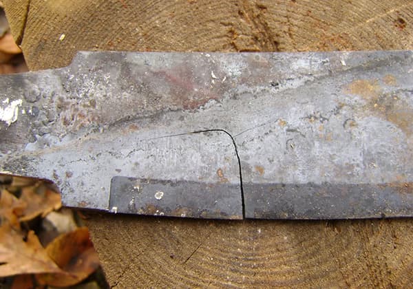
As shown in Fig. 1, through the observation of the scrapped parts after heat treatment, it is found that all quenching cracks of the parts appear in or near the inner holes of the parts.
In the macroscopic state, the cracks advance along the inner holes of the parts in a zigzag small serration shape, with a length of several millimeters to ten millimeters, and a depth of 2-5mm along the axial direction.
Generally, each part has several cracks.
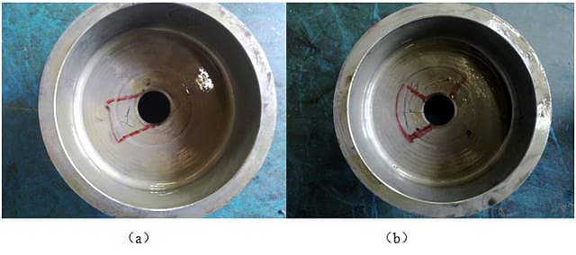
Fig. 1 macro photo of quenching crack of parts
(2) Chemical composition test
The cracked parts are sampled for chemical composition test.
The test results are shown in Table 1.
The chemical composition complies with GB / T 3077-1999 chemical composition and mechanical properties of alloy structural steel.
Table 1 chemical composition of 27SiMn Steel Parts (mass fraction) (%)
| Chemical element | C | Si | Mn | P | S |
| GB/T 3077 | 0.24~0.32 | 1.10~1.40 | 1.10~1.40 | ≤0.35 | ≤0.35 |
| Test results | 0.32 | 1.24 | 1.25 | 0.019 | 0.005 |
(3) Metallographic analysis
Metallographic observation shall be conducted by sampling at the crack part of the part.
As shown in Fig. 2, under the metallographic microscope, it can be clearly observed that the crack meanders along the grain boundary;
Decarburization and oxidation are not found on both sides of the crack, which should be caused by quenching;
Cracks crack along grain boundary, which should be intergranular fracture;
There are a large number of white reticulated structures at the tail end and both sides of the crack.
The microhardness test shows that the white reticulated structures are reticulated ferrite structures.
The inside of the grain is tempered sorbite structure and a small amount of pinnate upper bainite structure.
Metallographic observation is carried out on the core of the quenched parts.
As shown in Fig. 3, the matrix structure of the parts is tempered sorbite structure + white mesh structure and a small amount of upper bainite structure.
The microhardness of the white reticular structure was tested, and the microhardness value was about 300hv, which can be judged as reticular ferrite structure.
2. Discussion
In the quenched state of steel materials, there are generally two forms of ferrite structure:
The first form is quenched at sub temperature or normal temperature but the holding time is very short.
The ferrite structure is retained in the subsequent quenching and cooling because it is not completely transformed into austenite or has no time to transform, and its shape is in block or half crescent shape at the grain boundary or inside the grain;
The second form is quenching at normal temperature, but due to the slow cooling rate at high temperature during cooling, the ferrite structure will preferentially precipitate in the form of network at the grain boundary.
The different forms of ferrite structure in the matrix structure have a great impact on the properties of materials.
The first form is that the ferrite structure is not fully austenitized and is distributed in the grain boundary or grain inside the matrix structure in a block or semi crescent shape.
Generally speaking, it has a good effect on relieving quenching stress, reducing quenching cracks and improving low-temperature brittleness.
The reason is that the structural stress and transformation stress generated during martensitic transformation will be greatly relieved due to the good shape of ferrite structure.
In addition, the ferrite structure is distributed on the grain boundary in block or crescent shape, and more trace elements such as s and P can be dissolved, which has obvious effect on eliminating reversible temper brittleness and improving the cold brittleness of steel.
In the second form, due to the slow cooling speed at high temperature during the quenching process, the ferrite structure takes the lead in the form of network and precipitates along the grain boundary.
This structure has a great impact on the mechanical properties of the steel, which will greatly reduce the impact toughness of the material and improve the probability of quenching cracks.
The reason is that the ferrite structure is distributed at the grain boundary in a network shape.
Due to the low strength of the ferrite structure, more trace elements can be dissolved, which greatly weakens the strength of the grain boundary and reduces the impact toughness.
Once the structural stress and phase transformation stress of the material are too large during quenching, the crack will preferentially nucleate at the grain boundary where the network ferrite is located and crack along the grain boundary, resulting in quality accidents.
In this post, the crack parts of the quenched parts all appear at the inner hole.
It can be clearly observed from the metallographic structure of the quenched parts that there are a large number of network ferrite structures, and the cracks are meandering along the grain boundary, which indicates that there are problems in the quenching and cooling process of the parts.
From the above physical and chemical tests, it can be seen that the alloy elements of 27SiMn Steel, especially the carbon content, are higher than the upper limit, so the hardenability is better;
In general, the critical diameter of 27SiMn Steel can reach 38mm in 20 ℃ static water, and the effective thickness of the parts is 13mm.
Therefore, under normal conditions, the parts can be fully quenched in water.
The normal metallographic structure after heat treatment should be tempered sorbite structure.
However, from the metallographic structure observation in Fig. 2 and Fig. 3, it is abnormal that there are a large number of network ferrite structure and a small amount of upper bainite structure in the structure.
The quenching medium of parts is circulating tap water.
The cooling performance of water is very sensitive to temperature.
When the water temperature is higher than 40 ℃, the cooling performance will be greatly reduced, and its cooling capacity in the high-temperature region (500-700 ℃) will be sharply reduced, while the low-temperature cooling capacity in the low-temperature martensitic transformation region (200-350 ℃) will be less reduced.
This can be seen from Fig. 4.
This will easily lead to the following consequences:
The slow cooling of the parts in the high-temperature zone leads to the transformation of austenite structure into ferrite structure and distributed on the grain boundary in a network, weakening the grain boundary;
However, in the low temperature region, the cooling rate is too fast, the austenite transforms into martensite, and the structural stress is too large.
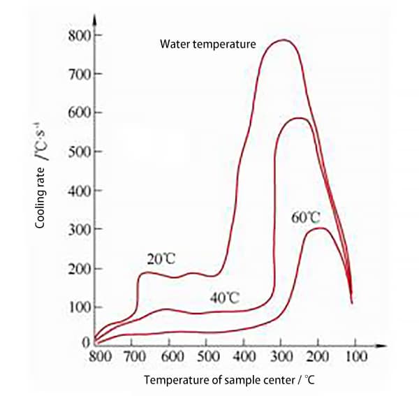
Fig. 4 Schematic diagram of cooling speed curve of water at different temperatures (still water)
Through field investigation and visit, the author found that the temperature control system of the salt bath furnace was normal and the thermocouple detection accuracy was qualified.
However, it was found that there were three problems in the heat treatment process of parts:
First, the joint door of the quenching water tank is damaged, and the circulating water of the quenching water tank cannot be replaced smoothly;
Second, the flowing cooling water (high water temperature) of the main electrode of the salt bath furnace flows directly into the quenching water tank, resulting in high water temperature of the quenching water tank;
Third, when the parts are actually quenched, the quenching interval of each furnace is short, and the volume of the water tank is small, and the update speed of the tap water in the water tank is not timely.
The above three factors cause the water temperature of parts to be too high during quenching. According to the investigation, it is inferred that the water temperature can be 50 ~ 60 ℃.
From this, it can be judged that the cooling performance of water in the high-temperature area of the parts is greatly reduced due to the high water temperature.
After the parts are quenched, the ferrite structure is distributed on the grain boundary in a net shape, resulting in a sharp decrease in the strength of the grain boundary.
However, the low-temperature cooling performance does not change much, resulting in too fast cooling speed, too large tensile stress and cracks along the grain boundary during the martensite transformation in the low-temperature area.
In addition, the shape of the parts and the quenching method also play a certain role in the cracking of the materials.
The shape of the parts is complex. It is heated in a salt bath furnace. The quenching fixture passes through the inner hole.
The parts are clamped in a vertical row, as shown in Fig. 5.
There are a large number of parts in each fixture, and the fixture is long.
When the traveling crane is used for quenching, due to the speed limit of the traveling crane, the water inflow of the fixture is slow when the parts are quenched, resulting in different cooling speeds between parts and different parts of a single part;
At the same time, because the quenching fixture passes through the inner hole of the part, the water flow in the inner hole is not smooth (the diameter of the inner hole of the part is 16mm), and the cooling speed of the inner hole is slow;
In addition, as shown in Fig. 5, when the parts enter the water, the position 1 is cooled first, while the position 2 is filled with air at its recess, so that the cooling of the inner hole at this position and its position 3 is slower.

Fig. 5 part clamp and quenching method
The slow cooling of the inner hole will make it easier to precipitate the net ferrite structure, weaken the grain boundary, and make the residual thermal stress value generated by cooling in the high-temperature area relatively small, while the structural stress generated by cooling in the low-temperature martensitic transformation area is large.
The superposition of the two will cause a large tensile stress state on the surface of the inner hole.
When the tensile stress value exceeds its tensile strength, cracks will be caused at the inner hole.
3. Conclusion and improvement measures
(1) The shape and quenching method of the parts lead to the slow cooling speed of the inner hole and the large tensile stress at the inner hole.
(2) During the quenching process of the parts, due to the damage of the quench water tank gate and other reasons, the water flow is not smooth, the water temperature rises, and the cooling performance of the water is greatly reduced.
The ferrite structure is distributed on the grain boundary in a net shape, resulting in a sharp decrease in the strength of the grain boundary.
Under the residual tensile stress, the crack breaks along the grain boundary.
In order to verify the above judgment, the author repaired the water tank door, controlled the quenching water temperature within 30 ℃ in the next batch trial production of parts (the same batch of materials), and increased the stirring force.
As a result, the quenching crack rate of parts was greatly reduced, less than 1 ‰, which verified the correctness of the above judgment.