This is one complete operation manual for the swing beam shearing machine, which is also very popular hydraulic shearing machine.
You can check out the Hydraulic Guillotine Shears Operation Manual in another post.
Standard features of the hydraulic shearing machine
The hydraulic shearing machine is designed for cutting metal-steel plates, with a capacity based on a plate strength of 450N/mm2.
Please adjust the plate thickness if cutting other materials with different strengths.
The machine features a sheet plate welded structure, which provides for easy operation and reliable performance.
Cutting is powered by hydraulic pressure, and the return is controlled by a nitrogen gas cylinder, which helps to protect the machine from overload.
The machine can be equipped with a digital display system or numerical control system, as requested by the customer.
A blade gap indicator is also provided for convenient and prompt adjustments.
The machine is equipped with an alignment device with lighting, and the cutting stroke can be adjusted to improve the efficiency of cutting narrow plates.
Additionally, front support arms and a back gauge are provided. The back gauge is mechanically transferable and its position can be displayed numerically or controlled by an NC controller through encoders, with micro-adjustment by a hand-wheel. The front supporting arms are equipped with rulers.
A rolling material support ball is provided on the worktable to minimize fishtailing with sheet bars and reduce friction resistance.
A safety fence has been installed to ensure safe operation.
The frame of the hydraulic shearing machine
Machine frame
Steel-welded plate with high rigidity features two cylinders fixed on the left and right vertical pole.
A vice cut-board is installed on the worktable for convenient adjustment of the lower cut-board, ensuring that the gap between the upper and lower cut-boards is aligned. A feed ball is also installed on the worktable for convenient and fast operation.
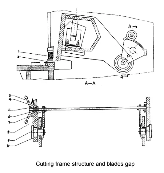
Cutting frame
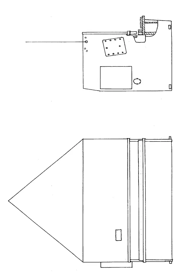
The high-rigidity welded plate is supported at the eccentric socket (9) and driven by the left and right cylinders and the stroke cylinder to complete the cutting process through pendulum repetition. (Refer to Figure 1). The vertical surface of the up-cut support is curved to maintain the alignment of the gap between the up-cut and low-cut.
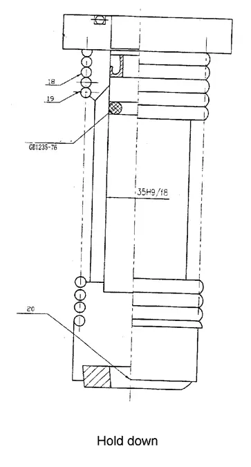
Pressure device (Hold down)
It consists of pressure feed cylinders installed on the support board in front of the machine frame. The oil flow in the pressure feed cylinder creates pressure that pushes down against the pull force of the stress spring (18), securing the press plate tightly. After cutting is complete, the cylinders are reset by the pull force of the stress spring. The pressure increases with the thickness of the plate. (See Fig. 3)
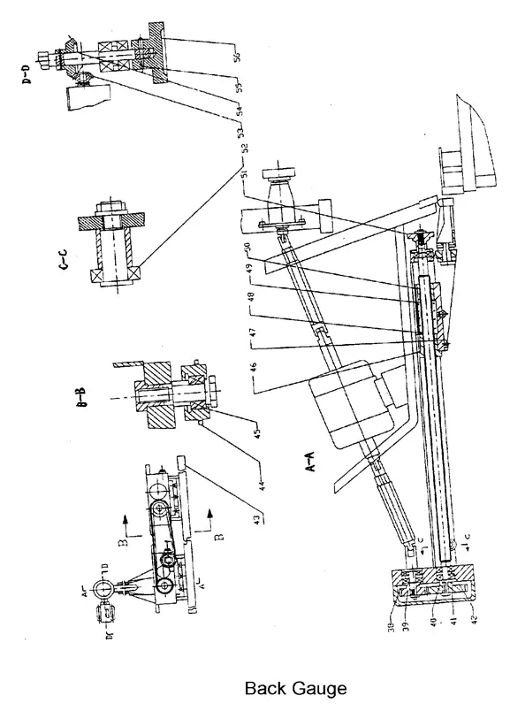
Front gauge and back gauge
Front gauge:
The worktable is equipped with a valve display on the ruler, allowing the mobile bar to be adjusted to the desired valve. Cutting thin steel plates can be conveniently done on the front gauge. The back gauge (refer to picture 5) is fixed on the up-cut board and moves up and down with it.
The back gauge is adjusted by a 0.55Kw motor, which reduces the torque through a gear and drives the control rod. By pressing the “+” or “-” button, the gauge can be adjusted forward or backward. In case the desired valve cannot be achieved through mechanical adjustment, the hand-wheel (50) can be turned to achieve the required valve, making the adjustment of the back gauge both convenient and reliable.
The standard range of the back gauge is 20-750mm. If the length of the cutting plate is longer than the maximum distance of the back gauge, the back gauge (43) can be removed to its minimum position and the board can be lifted up using the inclined surface of the support frame (47), allowing for cutting of any length of plate. (Refer to Fig. 4)
Installation of hydraulic shearing machine
Packing / Shipment of hydraulic shearing machine
All machines leaving the factory are packaged with a squaring arm and foot panel tied to the hand guard. The working tools and an operating manual are packaged into one box.
All exposed surfaces of the machine are coated with a rust inhibitor, which can be easily removed with kerosene or a solvent.
Lifting the hydraulic shearing machine
Use only approved and safe wire ropes to lift this machine from the two lifting points located at both sides of the machine. (See Figure 5)
Foundation
All our shears are designed to be installed on a foundation. Please refer to the attached foundation drawing for details.
Installation
This hydraulic shearing machine must be properly leveled for optimal cutting performance. This can be achieved by using a high-quality leveling gauge on the plate hold-down area.
Before leveling, ensure that you have five base plates (measuring at least 150 x 150 x 9mm) placed beneath the machine’s feet to prevent the leveling screws from digging into the concrete floor.
Once the machine is leveled, secure its position by filling the space under and around its feet with a cement grout mixture.
Electrical Installation
Make sure that the local power supply is compatible with this hydraulic shearing machine before turning on any electrical power.
Connect the power cable to the bottom left side of the electrical panel. Some machines may require a neutral wire.
The electrical diagram of the hydraulic shearing machine
Here are the drawings:
4.1 The following steps must be carried out by specialized personnel and are the responsibility of the owner.
- Verify the nameplate of the hydraulic shearing machine and ensure that its wiring matches the available power in your facility.
- If the required power does not meet the machine’s specifications, please contact your electrical supplier for assistance.
- Ensure that the power supply to the machine is fused, so that it can be fully disconnected for repair.
- Please refer to the attached electric drawings, as different controllers may have different diagrams.
4.2 All the operating buttons are fixed on the front control panel, with the exception of the foot switch SF. The symbols for each function are displayed above the buttons.
The steps for operating the digital display system are as follows:
- Open the electric box door and turn on the power switches QF1 and QF2 to power on the machine. Close the electric box.
- Press the key button SA1 to switch on the control circuit. The light HL1 will illuminate to indicate that the machine is powered on.
- Press buttons SB4 or SB5 to move the back gauge forward or backward.
- The position of the back gauge is displayed on the SICK mechanical displayer. The limit switches SQ3 and SQ4 are installed at the maximum and minimum travel of the back gauge, with a standard travel range of 20mm to 750mm.
- Press the lighting button SB3 to start the pump motor, which can be heard working.
- Use the button SA3 to select the cutting mode, either manual or auto.
- The illumination light is indicated by SA4. Turn it to 1 to start counting, and turn it to 0 to stop counting.
Hydraulic System
Clean the hydraulic oil
The cleanliness of the hydraulic oil in the hydraulic system is of utmost importance. Cleaning the oil tank is crucial.
When replacing the hydraulic oil, it is necessary to remove the cover of the oil tank. Clean the bottom of the tank using a towel (do not use cotton yarn), and then wash with cleaning gasoline or kerosene.
Due to the limitations of the tank cover, the arm may not reach the end of the tank. In such cases, wrap the towel around a bamboo or stick to wipe each corner.
To remove any dirty oil, loosen the leaking plug or brake valve.
Use a cleaning towel to thoroughly dry the sides and bottom of the tank until it is clean.
If necessary, roll a cloth at the welding seam or difficult-to-clean areas to remove any dirt, then put the cover back on.
Choose the hydraulic oil
The viscosity rating of hydraulic oil corresponds to its average viscosity at 40°C. If the hydraulic system operates at higher pressure and temperature and at a slower speed, a higher viscosity rating should be chosen.
It is recommended to use anti-wear hydraulic oil with an ISO VG46# rating (an average viscosity of 46 mm2/s at 40°C). If the machine will be operating at temperatures below 5°C for an extended period, it is recommended to use hydraulic oil with an ISO VG32# rating.
The use of the machine at very low temperatures (below -5°C) is not recommended, but if it is necessary, the machine should be allowed to idle for a while. An oil heater can be installed in the circuit if needed.
Under normal operating conditions, the oil temperature should not exceed 70°C. If necessary, an oil cooler can be installed.
Fill the oil
The oil used must be clean. Tighten the nut of the air filter and fill it through the air filter.
If you are using filling equipment with a filter, you can open the cover of the oil tank and fill it directly.
Observe the oil gauge, when the ram stops at the Top Dead Spot, the hydraulic oil should fill 80-90% of the interspaces.
Start the machine and let it idle first, then operate it at the maximum stroke to expel any air bubbles in the hydraulic circuit.
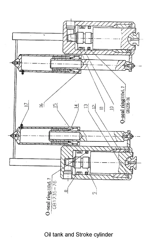
The working rule of the hydraulic system is as follows:
The cutting frame goes down:
When the magnetic discharge valve 3 is energized, pump 2 draws out the hydraulic oil, which flows through magnetic discharge valve 3 and into the hold-downs and the upper area of the main oil cylinder. The hold-downs piston goes down to press the metal plate against the force of the spring, and the oil pressure begins to rise.
When the pressure reaches the nitrogen gas pressure in the stroke cylinder, the cutting frame moves down to cut.
The cutting frame returns up:
When the cutting frame reaches the bottom dead spot, the magnetic iron YV1 of magnetic discharge valve 3 loses power due to a limit switch, and the cutting frame moves up due to the pressure from the nitrogen gas cylinder.
At the same time, the oil in the upper area of the main cylinder flows back into the oil tank through the magnetic discharge valve.
The hold-downs piston also moves up due to the force of the spring, and the oil returns to the oil tank through magnetic discharge valve 3.
When the cutting frame reaches the top dead spot, one cutting cycle is complete.
6. Standard control equipment
| Start button | To start the main motor running and Control circuit. |
|---|---|
| Stop button | To stop the main motor running and Control circuit. |
| Auto/Man mode selector switch | Select the working mode |
| In the Auto mode | -One step on the foot switch, the cutting frame will cut continues. |
| -Can command cut by foot pedal only. | |
| In the Manual mode | -One step the foot switch, the cutting frame will only do once cutting. |
| -Adjust the cutting stroke by return the rotating button on the panel. | |
| Foot pedal | Push to command cutting blade down and release to have top blade carrier rise in AUTO mode. |
| Illumination Light | Working light to shine at cutting blade area, operating at single phase power supply at 220V, 50Hz. |
Adjustment and operation of the hydraulic shearing machine
Adjust the gap between blades of the hydraulic shearing machine
The blade gap is crucial to both the quality of the cutting and the lifespan of the blades. Please adjust according to the gap adjustment table below.
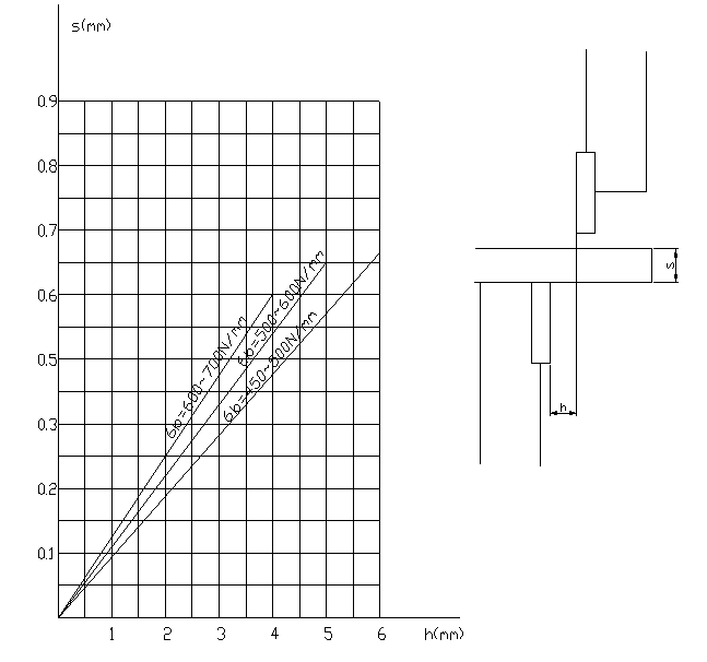
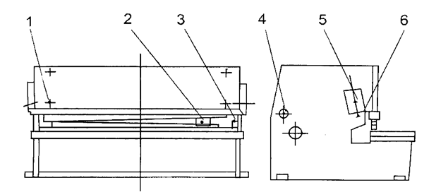
To adjust the gap (refer to Picture 2), you need to loosen the tight screw (4), then turn the handwheel (3) to the desired value, which should be calculated based on the thickness of the plate, and finally tighten the screw (4).
There is a ball valve (located on the right side of the machine, outside of the cylinder) that is used to measure the clearance gap between the upper and lower blades.
For more details: in manual mode, when the cutting frame reaches the bottom dead spot, quickly close the oil circuit, causing the cutting frame to remain at the bottom dead spot. Then, slowly turn on the ball valve, causing the cutting frame to move up step by step along the entire stroke. This will allow you to measure the clearance value of the gap between the blades.
Operation of hydraulic shearing machine
7.2.1 Preparation of Machine
(1) Remove the squaring arm and foot pedal from the hand guard area. Secure the squaring arm to the left-hand side of the machine table using bolts and the two side holes. The arm should be close to the electrical panel.
(2) Clean the components of any dirty oil, being careful to ensure that the ball valve is in the open position.
(3) Lubricate all necessary areas.
(4) Fill the oil tank with 200L of HL46 hydraulic oil for each machine under the 12mm model.
(5) Connect the earth line, turn on the power, and check the operation of all electrical components.
7.2.2 Starting the Machine
(1) Press the ‘START’ button and release.
(2) The ‘motor on’ indicator light should turn on.
(3) Change the mode selector from ‘MAN’ to ‘AUTO.’
(4) Step on the foot switch, causing the cutting frame to descend and make a cut.
(5) If the cutting frame does not descend, it is likely that the motor is running in the wrong direction. Turn off the power and reverse either of the two phase wires to restart the motor.
(6) The top blade carrier will rise and stop when it reaches the limit switch.
7.2.3 Motorized Back Gauge
(1) The motorized back gauge display should be accurately set in the factory and should correspond to the distance from the back gauge bar to the cutting edge.
(2) Press the ‘+’ button to bring the back gauge bar to the rear. The reading will increase and stop when it reaches the maximum travel limit switch L/S 3.
(3) Press the ‘-‘ button to bring the back gauge bar to the front. The reading will decrease and stop when it reaches the minimum travel limit switch L/S 4.
(4) The parallelism of the back gauge should be set in the factory, but can be calibrated as needed.
(5) Move the back gauge bar to the rear to remove the anti-rust coating before cutting.
Note:
(1) The pressure table should be on during cutting, and the pressure should be checked if it appears to be incorrect. The overflow valve may need to be adjusted.
(2) If any unusual noise or overheating of the oil tank occurs during operation, the machine should be stopped immediately. The temperature of the oil tank should not exceed 60°C.
Troubleshooting of hydraulic shearing machine
Machine Cannot Start
- Check incoming power supply.
- Check that Emergency Stop is release.
- Check the transformer output.
Machine Cannot Cut
- Check that the limit switch is engaged.
- Check that motor is rotated in a correct rotation.
- Check that foot paddle cable is not broken.
- Check that micro-switch inside foot paddle is working.
Ram Chattering on Down Stroke
- Counterbalance setting pressure is a little too high
- Just release the set screw a little to lower the setting
Machine Operates By Its Self
- Be sure that the Micro-switch inside foot paddle is not damaged.
- Foot paddle cable may be shorted to each other.
The fault and resolve of the hydraulic system
| Fault | Cause | Resolve |
|---|---|---|
| The hydraulic system no pressure and cutting frame no action | 1. The plug of magnetic exchange valve is a bad connection. | 1. Inspect the plug. |
| 2. The valve core is jammed by waste or becoming rude. All throttle valve hole of coincidence valve cannot flow. | 2. Disassemble the valve and clean. | |
| 1.Cutting frame returns slowly or cannot go up at the up-dead spot | The pressure of nitrogen gas is not enough. | Supply nitrogen gas for adding pressure |
| 2. The action of cutting frame and hold downs is inharmonious |
Maintenance of hydraulic shearing machine
Lubrication and Hydraulic Oil
This machine uses hydraulic oil of grade 46, and it should only be refilled or replaced with the same grade oil, such as:
- FIAT-HTF 46
- ENERGOL HLP 46
- ESSO NUTO H46
- SHELL-TELLUS S68
- TOTAL-AZOLLA 46
Lubrication program
The hydraulic oil in this machine should be changed after the first 1500 working hours and drained completely from the oil tank to remove any impurities that may have entered during assembly. The oil filter should also be changed and replaced with the same grade oil filter. Subsequently, oil changes should be performed every 5000 working hours.
Additionally, all grease nipple points should be lubricated every two weeks, which are located on the back gauge assembly.
| No. | name | flow | Internal time(h) | Type & brand |
|---|---|---|---|---|
| 1 | A top point and a bottom point on each return cylinder. | Small | 16 | Ca-lubrication Oil ZG-3 GB491-65 Mechanical oil N46GB443-84B |
| 2 | A point on the left and a point on the right of the rear stop sliding nut | Medium | 8 | |
| 3 | Two fulcrums for the oscillation of the upper knife frame, one on the left and other on the right | Small | 24 | |
| 4 | One on the left and the other on the right of the clearance shaft sleeve | Small | 48 | |
| 5 | Each spot on the piston rod of left and right cylinders | Medium | 8 | 4# carbon-lithium Q/SY1000-65 |
| 6 | Each one on the padding block of the left and right cylinder | Medium | 8 |
Note:
- Mix 50% Calcium-based lubrication oil with 50% mechanical oil for use.
- Mix 30% Carbon-Lithium lubrication oil with 70% mechanical oil.
- Replace the oil tank once every six months.
Changing of Shear Blade
Both the top and bottom shear blades are identical and interchangeable. To make the cutting frame go down to the lower dead spot, use the ball valve and turn off the machine.
First, remove the bottom blade, then the top blade. Loosen all the small set screws on the top blade carrier.
Clean the blades and blade housing/seat. Fix the top blade back first, then the bottom blade. If necessary, tighten the small set screws on the top blade carrier to close the blade clearance. Remember to check for minimum clearance and adjust the small set screws to close the blades as required.
CAUTION: Always engage qualified and experienced personnel to perform this job, as damage to the shear blades/machine or personal injury may result.
Grinding of Shear Blade
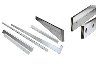
The Shear blade is rectangular in shape, and the upper blade has two cutting edges while the lower blade has four cutting edges. You only need to regrind the blade after all two or four edges have been used.
When regrinding, remember to only grind the thickness, not the height of the blade. The loss of grind-off thickness of the shear blades may result in the need to close in the top blade carrier by adjusting the screw in the tensioning bolt (next to the quick blade clearance lever).
Upper and lower blades
(Tooling drawings See the attached drawings)
Safety preventing and hydraulic shearing machine main construction
Note!
This section is only applicable to machines with special requirements and should not be referenced for other machines.
To ensure the safety of both people and equipment, we have designed safety equipment. The operator must not modify, remove, or disconnect the safety equipment.
10.1 Light Beam/Laser Beam
There is a light beam or laser (depending on the customer’s request). If the operator blocks the light curtain, the safety module will activate, and the ram will not be able to move downward to prevent operator injury.
10.2 Safety Grid
There is a safety grid located at the side and back of the machine to keep the operator away from hazardous areas. The safety grid is connected to the electrical system through a safety switch. If the safety grid is opened, the electrical system will start, and the machine will not be able to operate.
10.3 Emergency Stop
There is an emergency stop button located on the handle control station and hanging control station. In case of an error operation or accident, pushing the emergency stop button will cause the machine to stop all actions.
10.4 Hydraulic System
To prevent the dangerous falling of the ram, the system has a safety lifting valve. The valve cores of the exchange valve and safety lifting valve have a checking signal. If the valve core is abnormal, the checking signal will stop the electrical system to prevent falling injury. If the valve cores of the exchange valve and safety lifting valve cannot be reset, the valve should be checked.
10.5 Troubleshooting
Normal operation is safe. If any strange accidents occur, or when maintaining or repairing the machine, lock the safety grid, push the emergency stop button inside the uprights, and seek help. If your hands or any other body parts become clamped by the punch or sheet, push the emergency button, check the condition, then restart the machine. Switch the operating mode to the “inch” position, then push the handle return button, and the ram will return, allowing you to pull out the clamped parts.


Hello sir we have JIANGSU beam hydraulic machine but i would love to get your manual how do i pay so i can get it to teach my technician because they look the same. The manufature is not responding
Emmanuel
You don’t need to pay for it, you can read it at our site anytime you need.
Okey thanks
Hi sir, we are working on Hindustan shearing machine.
It’s drive shows error code 910 means high load.
And another error code shows 710 means high load. What can we do for it to fix this problem ?
Hi my machine Nitrogen leaked and found out seal depreciate. What is the standar bar to refill the nitrohen cylinder
This is depend on your machine’s capacity, generally 6-8Mpa for 4/4000 shears.
boa tarde, sou tecnico de manutencao industrial, temos uma maquina QC11-20×3200 hidraulic machine, gostaria de obter o manual para uma possivel manutencao
You can refer to this manual for QC11 series hydraulic guillotine shear:
http://www.machinemfg.com/hydraulic-guillotine-shears-operation-manual/
Hi, i have 6×2500 machine, when blade cut down but not goes up back, what poroblem are occurred? Plz guide me
Regards
Javed awan
Usually caused by lack of nitrogen, try adding nitrogen
I have a QC11Y-6×3200 HYDRAULIC SHEARING MACHINE. THE ACCUMULATOR NITROGEN LEAKED and the diaphragm was damaged. This parts are not available locally. How can I order a complete accumulator with nitrogen. Also we need the adaptor to fill nitrogen to the accumulator locaaly
Our sales will contact you.
DEAR SIR WE HAD QC12Y-6X2500 MODEL SHARING MACHINE . IN THIS MACHINE OIL LEAKS FROM ONE SIDE HYDRAULIC CYLINDER .AND I DON’T HAVE MANUAL FOR MACHINE PLEASE SUGGEST HOW TO ARREST LEAKS.AND SEND OIL SEAL DETAILS
The cylinders used by different manufacturers are different. I suggest you go to the manufacturer of the plate shear. Only they can provide the most accurate seal ring information.
we encounter a blast and a total damage on gas and oil system when our gas supplier wrongly filled our nitrogen cylinder with oxygen. we had QC12Y-8X2500 shearing machine. what is the cause of it and will the machine be fixed for further operation?
replace the nitrogen cylinder with a new one.
My machine is reading backwards,thus if you put in higher value then the stopper is moving back instead of going forward and vise versa.so can you please assist me please
Does your controller still works well, and what’s the brand and model?
will you please send the variable rake angle shearing machine circuit? i am maintenance person
You can refer to this post: http://www.machinemfg.com/hydraulic-guillotine-shears-operation-manual/