Laser welding is highly advantageous due to its fast speed, minimal deformation, aesthetically pleasing welds, and high strength. It is widely used in fields such as aviation, automobiles, and medicine.
Specifically, laser fusion welding is a non-contact welding process that creates a variety of welding seam shapes with excellent seam consistency. It has enormous potential in sheet metal manufacturing.
This article focuses on the application of sheet metal design in laser welding of housing structures with flanged 45° beveled joints.
Sheet metal design in the structure of laser welding box
The box body is made of 1.5mm thick 304 stainless steel and has dimensions of 200mm × 200mm × 115mm. The box is bent at angles of 90°, 90°, and 80° from bottom to top.
The structure of the box is illustrated in Figure 1.
Table 1 displays the laser welding parameters.
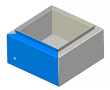
Figure 1 Schematic diagram of the box structure
| Welding process | Laser thermal conduction welding |
|---|---|
| Power (W) | 3000 |
| Speed (m / min) | 1.8 |
| Defocus (mm) | 10 |
Table 1 Laser welding parameters
In the traditional process of welding stainless steel box structures, it is common to perform grinding and polishing treatments after welding in order to achieve a more aesthetically pleasing end product. However, these subsequent procedures can be cumbersome and time-consuming, and may also result in welding deformation and penetration.
Laser welding, on the other hand, offers significant advantages in sheet metal welding, such as fast welding speeds, minimal deformation, and visually appealing welding seams. As such, finding ways to apply the benefits of laser welding, including its narrow welding heat affected zone and high precision, to box structure welding has become a pressing issue to address.
Design of overlap of laser welding box structure
In welded stainless steel box structures, the fillet weld of the box constitutes a significant portion of the overall welding process.
To achieve a round laser welding seam, we have optimized the amount of overlap in traditional welding techniques, as depicted in Figures 2 and 3. In these figures, t represents the plate thickness, a is the amount of overlap, b is the position of the laser center on the plate’s cross-section, and α denotes the laser tilt angle.
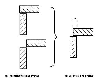
Figure 2 Improvement of fillet welding seam overlap

Figure 3 Laser welding overlap
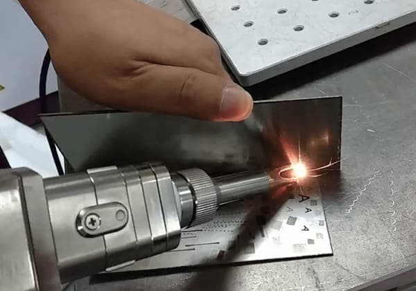
The optimized amount of overlap is welded using laser thermal conduction welding. The defocusing distance is precisely set to 10.00mm, and the focusing accuracy is maintained at 0.01mm through the use of an automatic focusing system.
With the aid of a high-magnification CCD camera, the b value can be accurately positioned, resulting in a round laser weld without the need for filler wire, as depicted in Figure 4b.
This optimization method for the amount of overlap is most suitable for plates with a thickness of 3 mm or less, wherein the values for a, b, and α are determined by the value of t.
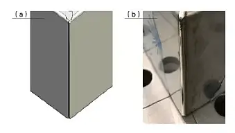
Figure 4 Schematic diagram of the optimization of the amount of overlap and the actual laser welding effect
Design of the corner release groove of the laser welding box structure
In welded stainless steel box structures, optimizing the corner relief groove is crucial as it directly impacts the effectiveness of the bottom structure of the box.
In traditional welding processes, rectangular or rounded corner relief grooves are commonly utilized. However, such corner relief grooves can easily result in weld-through or insufficient welding when using laser welding techniques.
The schematic diagram of the corner relief groove is illustrated in Figure 5.
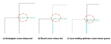
Figure 5 Schematic diagram of corner release slot
By utilizing the laser welding corner relief groove process block, the structure of the product can be optimized.
With laser welding, a complete and rounded welding effect can be achieved, requiring almost no secondary treatment and greatly reducing subsequent processing time, as demonstrated in Figures 6 and 7.

Fig. 6 Schematic diagram of laser welding design of corner release groove
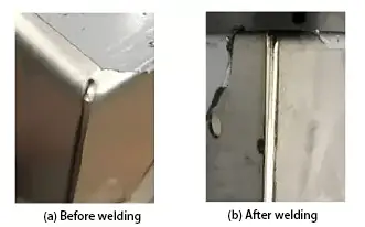
Figure 7 Actual laser welding effect of the corner release slot
Design of 45 ° bevel interface for laser welding box structure flanging
In the box structure made of welded stainless steel, the flange’s 45° bevel interface has difficulty closing tightly due to the amount of bending deformation, as illustrated at A in Figure 8. This issue poses a significant challenge for laser welding.
Hence, the interface design directly impacts the welding quality of the box structure. Additionally, a considerable gap will exist at B, making direct laser welding difficult to manage.
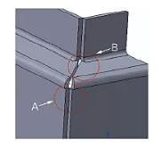
Figure 8 Schematic diagram before optimization
To address this issue, we have optimized the cabinet structure. In the design process, a portion of the metal from the step surface was removed, and two smaller step surfaces were extended, as depicted in Figure 9a.
During unfolding, the previously cut portion is compensated by using the end surface as a reference, as shown in Figure 9b and 9c.
At B in Figure 8, two stepped surfaces are alternatively extended to increase the amount of metal compensation, which makes up for the gap created in that area. This solution is illustrated in Figure 9d.

Figure 9 Schematic diagram of the sheet metal design of the 45 ° beveled flange interface
Figure 10 demonstrates the result of the laser welding process.
As shown in Figure 10a, the interface is tightly sealed, meeting the requirements of the laser welding process. The welding seam’s surface is smooth and aesthetically pleasing, with a natural transition and no sink or welding defects visible.
Moreover, as shown in Figure 8, the gap at B is also well-filled, demonstrating the effectiveness of the optimization solution implemented.
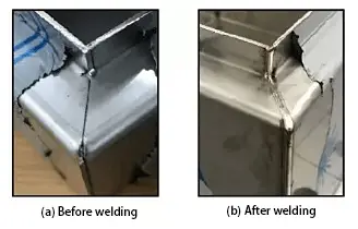
Figure 10 Laser welding effect of flange 45 ° bevel interface
Conclusions
As the welding process continues to evolve, traditional sheet metal design schemes will gradually become outdated. Similarly, as laser welding gains wider adoption in the sheet metal industry, there will be a need for new laser welding sheet metal design solutions. It is imperative to develop and introduce innovative designs that are better suited for the capabilities and limitations of the laser welding process.
Nice post!