Compared with traditional blanking+subsequent processing, the straight tube laser cutting efficiency has obvious advantages in production efficiency and labor cost.
It can realize the one-time processing of parts from raw materials to finished products.
The high integration of processing procedures can greatly reduce the problems of high labor, logistics and storage costs in traditional multi-process processing.
Moreover, the full automation of the processing process can greatly improve the consistency of parts for subsequent automatic welding convenience in assembly, etc.

Previously, due to the late start of domestic-related enterprises, most of the equipment was imported.
In recent years, with the improvement of the technical level, the straight tube laser equipment has been widely localized.
With the continuous development of domestic related fields in recent years, the functions of various domestic equipment have been improved continuously, and the price has decreased year by year, which has significantly increased the popularity of straight tube laser equipment.
Process discussion
Although the straight tube laser cutting has various advantages compared with the traditional processing method, due to the different processing methods, the processing process and some details of the finished parts are slightly different from the traditional mechanical processing, which requires targeted identification.
In combination with our actual operation mode and on-site improvement cases, the following three aspects will be discussed: end path compensation, improvement of open section profile cutting path loss, and different kerf compensation methods of air cutting and oxygen cutting.
Related reading: Things You Should Know About Laser Cut Kerf
End path compensation
This part mainly explains from two aspects:
First, the rectangular pipe or square pipe end bevel is cut and assembled with the plane; The second is the butt joint of the intersecting line of circular pipes.
⑴ Pipe end bevel and plane assembly.
The end bevel is a common part state, which has a high probability in daily production. The rectangular tube is taken as an example for analysis and explanation.
Fig. 1 and Fig. 2 respectively show the theoretical state and actual state of the rear end head of the metal cutting process.
It can be seen that the actual state under the rear end head of the traditional metal cutting process is consistent with the theoretical state, and the whole section is a straight line from the top view, so there will be no discrepancy between the real object and the drawing, nor will there be quality disputes.
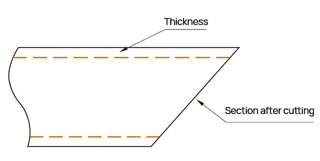
Fig. 1 Theoretical state of metal cutting

Fig. 2 Actual Status of Metal Cutting
Laser blanking is different from traditional blanking.
Laser blanking is that the laser cutting head cuts along a certain path to obtain the required end shape.
When cutting, the base material is melted along the cutting path through high-energy beams to complete the separation of materials, which leads to the illegal direction between the next path and the previous path.
After cutting a section of the path, the actual section will protrude a section of material thickness or lack a section of material thickness, that is, “excess material” or “missing material”, as shown in Fig. 3 and Fig. 4.

Fig. 3 Schematic diagram of laser processing end

Fig. 4 Status after actual cutting
The state shown in Fig. 4 (b) has little impact on the actual use, unless there are special requirements for strength and additional strengthening is required, which will not normally affect the subsequent use.
However, the state shown in Fig. 4 (a) will cause differences between the actual and theoretical mating surfaces due to “excess material”, and the “excess material” part will interfere with the matching parts, resulting in dimensional deviation, as shown in Fig. 5 and Fig. 6.

Fig. 5 Schematic Diagram of Matching Deviation Caused by “Too Much Material”

Fig. 6 Actual state of the fitting deviation caused by “excess material”
In the figure, the blue line is the actual fitting line, and the black line is the theoretically required fitting line.
It can be seen from the schematic diagram that there is an included angle X between the actual fitting line and the theoretically required fitting line due to “excess material”, which will have two effects on the subsequent sequence: due to interference, parts cannot be put into the fixture normally;
The position deviation of the matched parts affects the accuracy of the whole assembly.
It can be seen from the above analysis and comparison that, for the parts processed by the end bevel, the compensation of the cutter path should be considered in the path layout before laser cutting.
The “excess material” phenomenon should be avoided by adjusting the cutting path, which has an important impact on the processing quality of such parts. The specific path modification is shown in Fig. 7.

Fig. 7 Comparison before and after path compensation
In the figure, the sky blue line is the path before compensation, which will cause “excess material” phenomenon.
The green line is the path after compensation. After adding path compensation, the section state after cutting can be significantly improved, as shown in Fig. 8.

Fig. 8 Part Status after Compensation
The fitting diagram after adding path compensation is shown in Figure 9, and the actual fitting state is shown in Fig. 10.
It can be seen from the figure that the absolute positions of the actual two parts will not change, and the quality of the assembly can be effectively guaranteed.
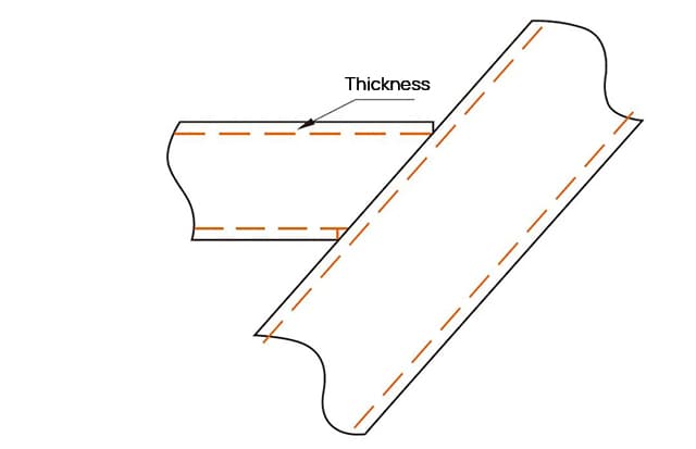
Fig. 9 Schematic Diagram of Matching after Compensated Cutting

Fig. 10 Actual matching state after compensated cutting
(2) Butt joint of circular pipe intersection line.
Coincidentally, due to the influence of the laser cutting processing method, if the path is not adjusted during the butt joint of the intersecting lines of circular tubes, the material thickness will also be “excess material”, resulting in interference in the coordination.
Taking the overlapping of two φ25mm and φ30mm pipes as an example, φ30mm pipe is a lapped pipe fitting.
See Fig. 11 for the schematic diagram of theoretical overlapping and Figure 12 for the theoretical shape of the end of φ25mm pipe fitting.
It can be seen that the end of φ25mm pipe fitting is a sharp angle, that is, there is a certain radian on the material thickness.
However, during the laser cutting of straight pipes, the material thickness direction is straight after cutting, perpendicular to the axis direction of the pipe fitting, and there is also an “excess material” phenomenon.
It is bound to cause interference of the mating surface, as shown in Fig. 13.

Fig. 11 Schematic Diagram of Theoretical Lapping

Fig. 12 Theoretical shape of Φ25mm pipe fitting
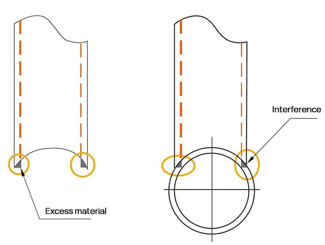
Fig. 13 Effect picture before compensation
In view of this, when cutting pipe fittings of this shape, the problem of end compensation should also be considered.
Like rectangular pipes, modify the cutting path, add path compensation, and optimize the path, as shown in Fig. 14.

Fig. 14 Coordination Effect after Compensation
It can be seen from Fig. 14 that the green line in the red circle is the path after compensation is added, and the sky blue line is the path before compensation is added.
It can be seen that after compensation is added, the cutting position of the long end of the pipe shape changes, but the “excess material” phenomenon has disappeared.
In the actual cutting, although the defects such as slag hanging will still have a certain impact due to this compensation, these effects are very small.
It will not greatly affect the subsequent use and the size of the assembly.
Cause Analysis and Solution of Path Loss of Open Section Profile
At present, straight tube laser can not only cut closed profiles, but also cut open section profiles such as channel steel and angle steel.
Different from rectangular tubes and square tubes, the external surface of open section profiles is mostly angular and there is no R angle.
Because the section is not closed, the cutting path is not closed. In our early production, path loss often occurs.
This phenomenon only exists in the processing of open section profiles.
Taking angle steel as an example, the cutting path is lost as shown in Fig. 15.

Fig. 15 Missing cutting path of angle steel
In view of this phenomenon, we tried to solve it from the perspective of software path generation.
After a long time of verification, the software automatically generates paths that are good and bad, without regularity.
Therefore, when this phenomenon occurs, we can only stop using the software’s automatic path generation function and plan cutting paths manually.
Although the problem has been solved, manual path editing is slow, time-consuming, and extremely inconvenient to use.
In view of the above phenomenon, the product was partially optimized.
The fillets were filleted at the red circle position in Fig. 16.
The corners would not appear when the fillets were tangent, and the fillets were tangent to two adjacent edges, so that the system defaulted them as one edge.

Fig. 16 Round corner of R5mm at corners
After the part is filleted, the straight tube laser program generation system is used to generate the path, and the path loss phenomenon disappears, as shown in Fig. 17.
To verify whether this phenomenon is a case, change and verify such parts one by one.
Fillet the corners of parts with path loss, and then use the system to generate the required path. After one year of verification, path loss has not occurred again.

Fig. 17 Newly generated path
Through this verification, it can be concluded that for open section profiles such as angle steel, its section is not closed, which has a certain impact on the actual path generation.
It is uncertain whether it is the bug of the program itself or the defect of the underlying logic.
At present, this phenomenon cannot be completely avoided on the Pentium and Trumpf straight tube laser equipment used by our company, but it can be avoided through the operation of local fillets.
At present, it is a relatively reasonable and effective solution.
Different kerf compensation methods for air cutting and oxygen cutting
With the development of the domestic laser industry, the low-cost air cutting technology has gradually matured and the market application has gradually increased.
Taking our company as an example, we have always used oxygen cutting before, but the newly purchased straight tube laser cutting equipment has been switched to air cutting in recent two years.
Compared with oxygen and nitrogen cutting, the most intuitive difference is that the processing cost is greatly reduced.
Because the air itself is around us, the use of air cutting only needs to consider the electricity cost incurred when the equipment itself is used, and no additional auxiliary gas costs need to be calculated.
Although air cutting will lead to burrs and slag on the cutting surface, for profiles, such defects mostly exist on the inner surface of profiles, which has relatively little impact on the external surface.
In addition, our pipe fittings are mostly used for various structural parts, which has relatively less strict requirements on the appearance of the kerf, so the impact on our actual production is relatively small.
After the early commissioning and a period of production of our equipment, we found that compared with oxygen cutting, the kerf compensation must be considered when generating the path.
The wall thickness of our common pipes is 2~5mm. The original fast laser cutting machine uses oxygen cutting, and the size of the cutting nozzle is mostly 0.5~1.5mm.
The problem of kerf compensation is not considered in daily production.
However, after the new equipment using air cutting is put into use, it is found that the size of the cutting nozzle reaches 3mm, and the problem of large fitting clearance of parts is often reported later.
After comparing the real objects cut by the two cutting methods, it is finally found that the problem lies in the kerf compensation.
In the theoretical state of part cutting, we all default that the kerf width is infinitely small;
In the actual cutting process, the laser beam has a certain diameter, which leads to three ways in the actual cutting process.
Assume that the theoretical contour length is L, the width is W, and the laser beam diameter is D.
(1) Mode I: the center path of the laser beam diameter coincides with the theoretical contour line, as shown in Fig. 18.
The actual size of the contour after cutting in this way: Wactual=Wtheoretical – D, Lactual=Ltheoretical – D.
The actual size is one cutting nozzle diameter smaller than the theoretical size.

Fig. 18 Mode – Cutting
(2) Mode 2: The outside of the laser beam diameter coincides with the theoretical contour line, as shown in Fig. 19.
In this way, the actual size of the contour after cutting: W actual=W theoretical – 2D, L actual=L theoretical – 2D, and the actual size is smaller than the theoretical size by two cutting nozzle diameters.

Fig. 19 Cutting in Mode II
(3) Mode 3: the inner side of the laser beam diameter coincides with the theoretical contour line, as shown in Fig. 20.
The actual contour line of this cutting method coincides with the theoretical contour line.
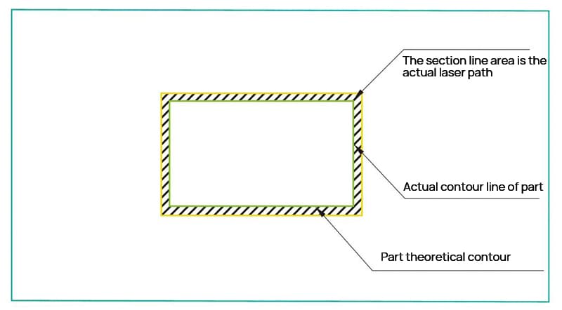
Fig. 20 Cutting in Mode III
When cutting in the above three ways, the part cut off in the middle is the required part.
If the part cut off in the middle is scrap, the reverse is required.
It can be seen from the above three states that the actual laser cutting is affected by the beam and the diameter of the cutting nozzle, and the actual cutting path actually has a certain impact on the overall dimensions of the parts: when using oxygen cutting, due to the combustion supporting effect of oxygen, the cutting nozzle diameter does not need to be too large to achieve the required energy intensity, and no matter what the cutting method has little impact on the actual contour;
However, when air cutting is used, the oxygen content in the gas decreases and the combustion supporting effect decreases, leading to an increase in energy.
This is reflected in the production that the diameter of the cutting nozzle is too large.
The diameter of the cutting nozzle used by our company for on-site air cutting all reaches 3mm, and the diameter of the cutting nozzle is too large, leading to the reduction of tolerance deviation and the increase of dimensional accuracy changes.
Therefore, when using air cutting, the slotting compensation must be considered when generating the path to ensure the required part accuracy.
Related reading: The Application of Air as Auxiliary Gas in Laser Cutting
Conclusion
With the development of the domestic laser industry, straight tube laser equipment has now become a relatively mature equipment.
Most of the parts can be processed domestically, and the market share has gradually increased.
The above analysis is only a small part of the problems that our company found in the use of straight tube laser equipment that affects the production accuracy of parts.
We need to pay attention to the problems in the actual path generation, hoping to bring some help or inspiration to our colleagues in the industry.