Basic knowledge of metal stamping process
1.1 Metal stamping process characteristics and applications
Stamping definition
What is stamping?
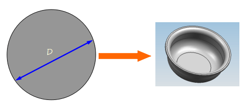
The definition of stamping: at normal temperature, a metal (or non-metal) sheet is pressed on a stamping press machine by a stamping die to cause separation or plastic deformation, thereby obtaining parts having a certain shape, size and performance.
From the concept of stamping:
(1) Stamping is carried out at room temperature, that is, it does not require heating, so it is called cold stamping.
(2) The objects of stamping processing are all sheets, so it is also called sheet metal stamping.
(3) Stamping is done by equipment and molds. It needs three elements: punch (equipment), mold, and raw materials.
(4) Stamping is one of the basic forms of plastic deformation.
Metal stamping characteristics and applications
(1) High productivity, simple operation, and easy mechanization and automation.
(2) High dimensional accuracy and good interchangeability.
(3) The material utilization rate is high, generally up to 70%~85%, and some up to 95%.
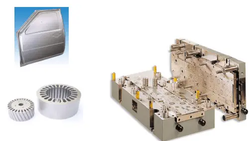
(4) Shape-complex parts that are difficult to machine or cannot be machined by other machining methods, such as thin-shell deep-drawing parts, are available.
(5) Parts with light weight, good rigidity and high strength can be obtained.
(6) No heating is required, energy can be saved, and the surface quality is good.
(7) When the mass is produced, the product cost is low.
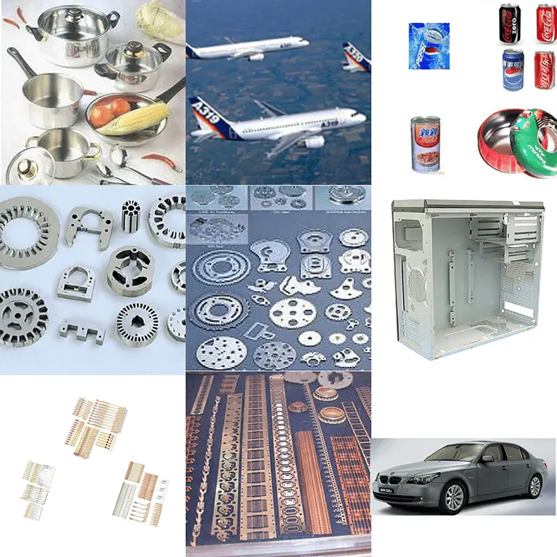
It can be seen that stamping can combine high quality, high efficiency, low energy consumption and low cost, which is incomparable with other processing methods.
Therefore, the application of stamping is very extensive. For example, in the automobile and tractor industries, stamping parts account for 60%~70%, instruments and meters account for 60~70%, and including other various stainless steel tableware in daily life.
From fine electronic components, instrument pointers to heavy-duty car covers and girders, as well as aircraft skins, stamping is required.
Disadvantages of stamping
The mold manufacturing cycle is long and the cost is high. Because it uses traditional processing methods and means and traditional mold materials
However, with the advent of advanced mold processing technology and non-traditional mold materials, this shortcoming can be gradually overcome.
Such as:
- Making molds from low melting point alloy materials
- Manufacturing molds using rapid prototyping
- Economic mold
In short, the mold industry is a country’s basic industry, the level of mold design and mold manufacturing has become a measure of the level of product manufacturing in a country.
Developed countries attach great importance to the development of molds.
Japan believes that “mold is the driving force for entering a wealthy society”;
Germany: “the emperor in the metal processing industry”;
Romania: “the mold is Golden Touch”; the mold is considered to be a stone in the international arena industry.
However, the molds here also include molds, forging dies, die-casting dies, rubber molds, food molds, building materials molds, etc., but currently the cold dies and plastic molds are the most widely used, each accounting for about 40%.
1.2 Stamping process classification
- Classified by deformation properties
- Separation process
- Forming process
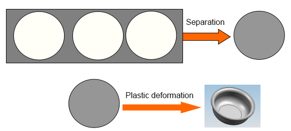
(1)Separation process
During stamping, the material to be processed is deformed by external force.
When the shear stress of the material in the deformation zone reaches the shear strength of the material, the material is sheared and separated to form a part of a certain shape and size.
The separation process mainly includes cutting, punching, blanking, notching, slicing etc.
The separation process is indicated as below:
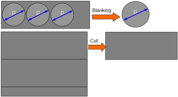
Separation occurs but does not change the shape of the space.
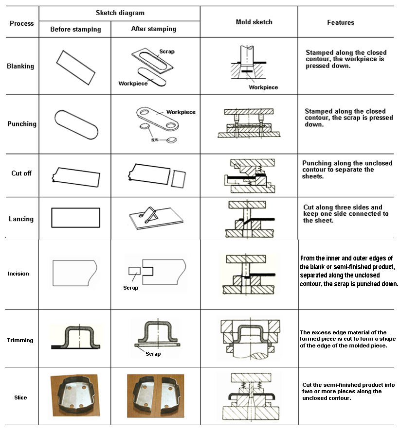
Table 1-1 Separation process
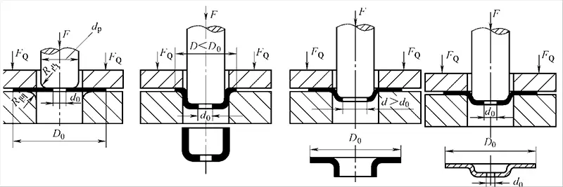
(2)Metal forming process
During stamping, the material under the action of the external force, the equivalent stress of the material in the deformation zone reaches the yield limit σs of the material, but does not reach the strength limit σb, so that the material only plastically deforms, thus obtaining parts of certain shape and size.
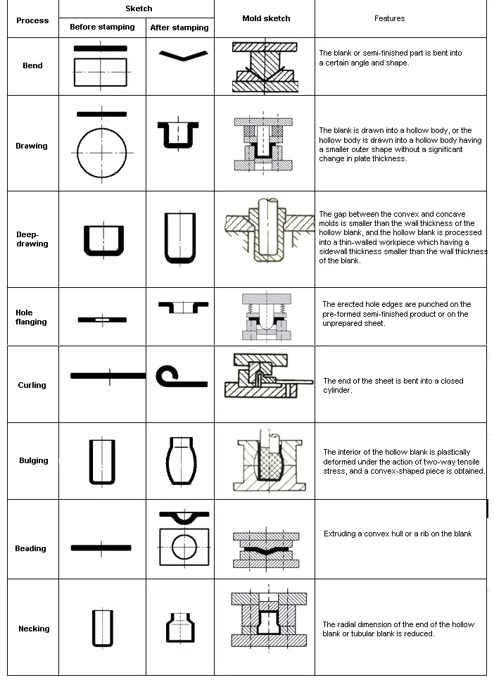
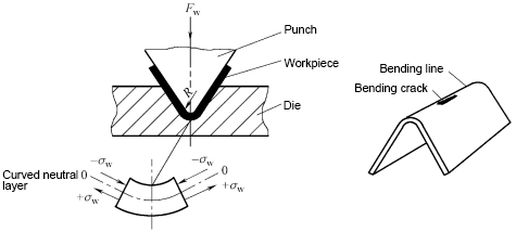
The forming process mainly includes bending, deep drawing, turning, shrinking, bulging, etc.
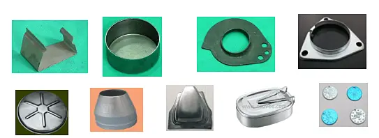
The forming process is shown as follows:
Only change the shape of the blank, no separation occurs.
Table 1-2 Forming process
- According to the nature of the deformation zone
- Elongation type forming: The maximum principal stress of the deformation zone is tensile stress, and the failure mode is tensile cracking, which is characterized by thickness thinning.
- Compression type forming: The maximum principal stress of the deformation zone is compressive stress, which is characterized by thickening of the thickness and the form of failure is wrinkling.

- According to the basic deformation method
- Blanking
- Bending
- Deep drawing
- Forming
- According to the combination of processes
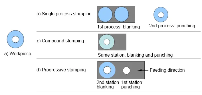
- Single process stamping
- Compound stamping
- Progressive stamping
1.3 Stamping material
Basic requirements for stamping on sheets
- Meet performance requirements
- Meet the requirements of the stamping process
Satisfying the performance requirements is the first, and meets the stamping process requirements as much as possible while meeting the performance requirements.
1.3.1 Process requirements for stamping materials
1.Stamping forming performance
Stamping forming performance refers to the ability of the sheet to adapt to the stamping process.
Two kinds of instability:
- Tensile instability – local necking or fracture under tensile stress;
- Compression instability – instability wrinkles under compressive stress.
The former is like the necking phenomenon in the low carbon steel tensile test, and the latter is the instability phenomenon of the pressure bar.
Thus, there is a forming limit, which is divided into an overall forming limit and a local forming limit. The higher the forming limit, the better the press forming performance.
How to measure the stamping forming performance of the sheet?
(1) Crack resistance refers to the ability of a sheet to resist damage during deformation.
(2) Pasteability refers to the ability of the sheet to conform to the shape of the mold during the press forming process.
(3) Shapeability refers to the ability of a part to retain its shape in the mold after demolding.
The stamping forming properties of the sheet can be measured by the mechanical properties of the sheet. Mechanical properties can be obtained through experiments.
Sheet metal forming performance test method:
- Direct test: The actual stamping process is directly simulated using special equipment.
- Indirect test: The general performance of the material is obtained by means of stretching, shearing, hardness testing, metallographic testing, etc. using general equipment.
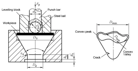
(1) Direct test method
Like cone cup test(GB/T 15825.6-2008)
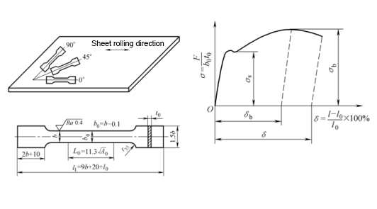
(2) Indirect test method
Such as tensile test of low carbon steel, etc.
Mechanical indicators affecting press forming properties
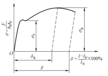
(1) Total elongation δ and uniform elongation δb
δ is good → Allows for large plastic deformation
(2) Yield ratio σs /σb
σs/σb is small → good crack resistance, shape fixing, and good moldability
(3) Modulus of elasticity E
Large elastic modulus E → good shape
(4) Hardening index n
n is large → not easy to crack
(5) Plastic strain ratio γ
γ = εb /εt is big → Good resistance to cracking
(6) Plastic strain specific anisotropy coefficient
Δγ =(γ0 +γ90 – 2γ45 )/2 is big → The more different the anisotropy
- Chemical composition requirements: The different content of some elements in the steel will result in different plasticity and brittleness of the material.
- Requirements for metallographic structure: Different metallographic structures can lead to different mechanical properties such as strength and plasticity.
- Requirements for surface quality: Requires a smooth surface, no oxide scale, cracks, scratches and other defects.
- Requirements for material thickness tolerance: A certain thickness corresponds to a certain mold gap, and the material thickness tolerance should conform to the national standard.
1.3.2 Common stamping materials and cutting methods
A.Common stamping materials
- Metal sheet: ferrous metal; non-ferrous metal
- Non-metallic sheet: rubber board, rubber sheet, plastic board, etc.
Related reading: Ferrous vs Non-ferrous Metals
Metal sheet specifications: steel strip, steel plate, slit steel strip, etc.
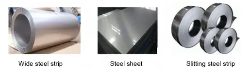
Size range of steel plates and strips (GB/T708-2006)
1) The nominal thickness of steel plate and steel strip (including slitting steel strip) is between 0.3mm and 4.0mm, and the steel plate and steel with nominal thickness below 1mm have any size in multiples of 0.05mm; the nominal thickness is above 1mm. Steel plates and steel are available in any size in multiples of 0.1 mm.
2) The nominal width of steel plates and steel strips is between 600mm and 2050mm, and there are any sizes in multiples of 10mm.
3) The nominal length of the steel plate is between 1000mm and 6000mm, and any size in multiples of 50.
4) According to the requirements of the purchaser, steel plates and strips of other sizes can be supplied through negotiation between the supplier and the buyer.
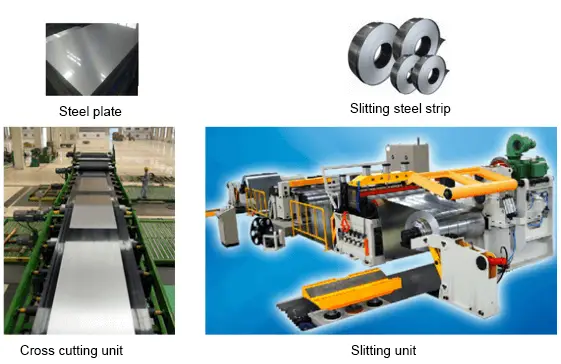
- Stamping material blanking method
(1) Shearing machine cutting
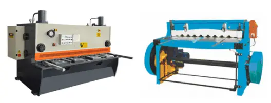
(2) Disc shearing

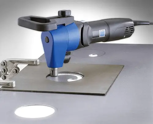
(3) Other cutting methods
- Laser cutter
- Plasma cutting machine
- High pressure water cutting machine
- Wire EDM machine
- Electric punching, etc.
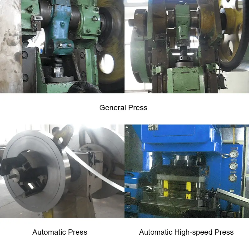
1.4 Stamping equipment
Selection principle of stamping equipment:
- The nature of the stamping process: separation or molding process
- The press force: open, closed
- Mold structure
- Mold closing height, contour size
- Production batch
- Cost of production
- Product quality
- Combine the existing equipment conditions of the workshop
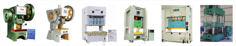
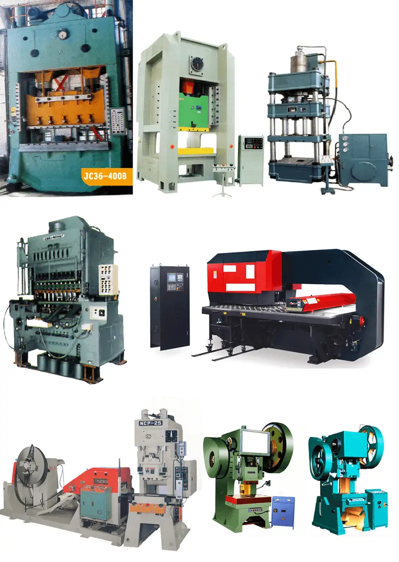
Stamping equipment type:
- According to the different driving force of the slider, there are mechanical presses, hydraulic presses and air presses;
- According to the structure of the bed, there are open and closed presses;
- According to the number of sliders, there are single action (one slider), double action (two sliders) presses, etc.;
- According to the number of connecting rods, there are single points (one connecting rod) press, two points (two connecting rods) press, four points (four connecting rods) press, etc.
- ……
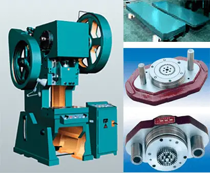
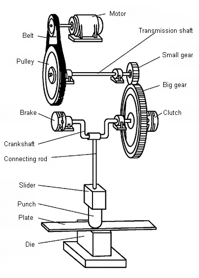
Working principle and main components of crank press
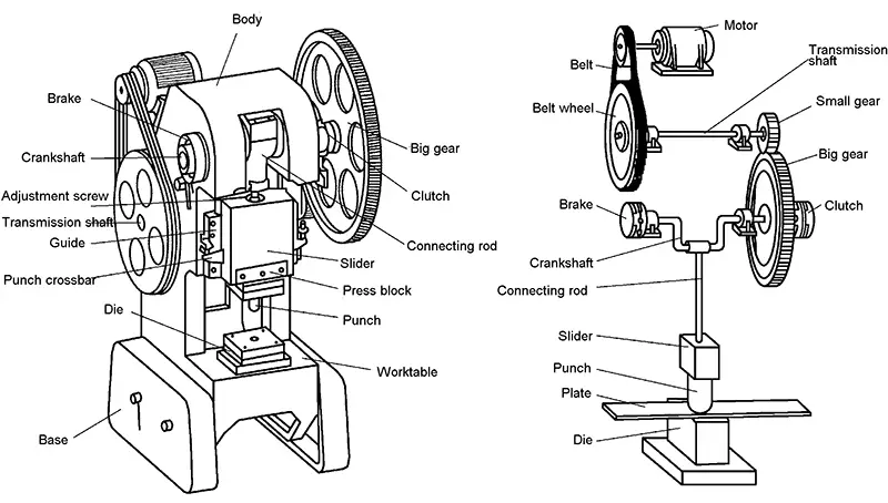
(1) Working mechanism
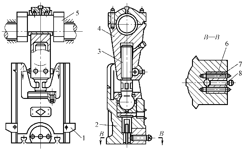
Crank and link mechanism: The crank link mechanism is composed of a crankshaft, a connecting rod and a slider. The length of the connecting rod can be adjusted to suit different sizes of molds.
Motor, belt, flywheel, gear, etc.
(3) Operating system
Air distribution system, clutches, brakes, electrical control boxes, etc.
(4) Supporting parts
Body: open, closed
(5) Auxiliary system
Pneumatic system, lubrication system
(6) Attachment
Press model and technical parameters
(1) Model
1) Forging machine type:
- J–mechanical press
- D–forging machine
- Y–hydraulic press
- A–shearing machine
- Z–automatic press
- W–bending restriking press
- C–hammer
- T–other
2) Crank press code description JB23-63A
- J–press machine category
- B–variant design code
- 2–column of the press
- 3–level of press
- 63–nominal pressure
- A–Improved design number
- “63T-open double column tiltable second modified press”
(2) Technical parameters
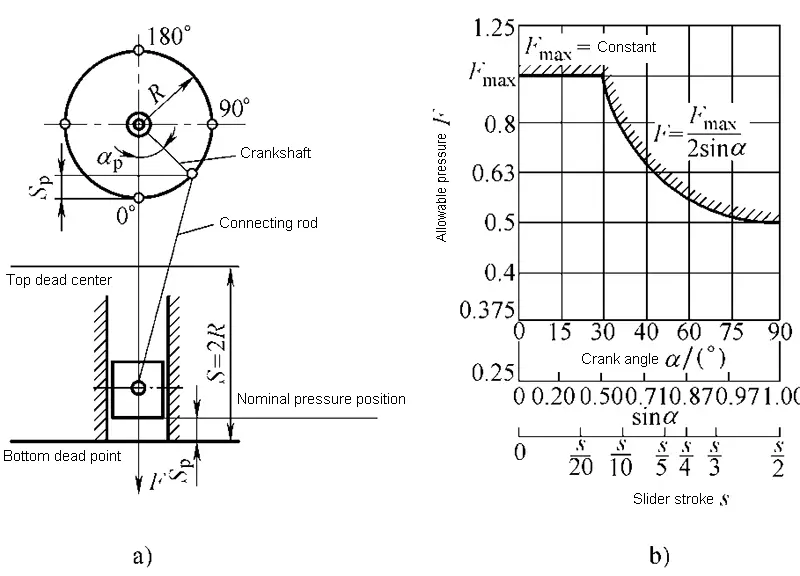
- Nominal pressure F
- Nominal pressure stroke SF
- Slider stroke S: top dead center → bottom dead center
- Slider stroke times n: top dead center → bottom dead center → top dead center
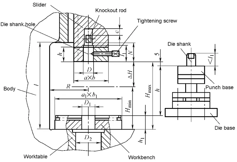
- Pressing height of the press
- Workbench board and slider bottom size
- Throat depth C
- Mold hole size
Basic theory of stamping process
2.1 Basic concept of plastic forming
- Elastic and elastic deformation
- Plasticity and plastic forming
- Plasticity index
- Deformation resistance
- Internal force and stress
Different materials have different plasticity under the same deformation condition, and the same material will have different plasticity under different deformation conditions.
2.2 Plastic forming mechanics
- Stress state
- Strain state
- Yield criterion (plastic condition)
- Stress-strain relationship during plastic deformation
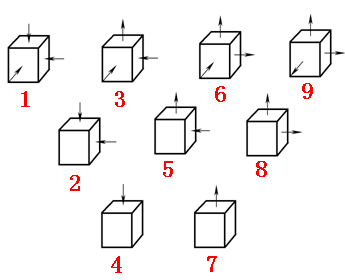
3 main strain states:
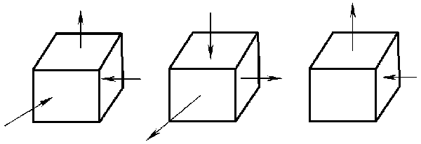
9 types of principal stress states:
2.3 Basic law of plastic forming
- Work hardening law
- Unloading elastic recovery law
- Law of least resistance
- Plastic deformation volume invariance law

4 Types of Metal Stamping Process
Now, let’s dive into the following four different stamping processes.
A fine descriptive piece of essay giving a novice a full knowledge of the stamping process. It not only give knowledge but also encourage a person to look for further knowledge. Thanks very much.
You’re welcome.