1. Definitions
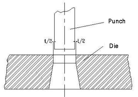
The cross-sectional area of the punch in a blanking die is typically smaller than the size of the die hole. There is a specific space, known as the clearance, between the punch and the die. This can be seen in the illustration below.
2. Influence of clearance on the quality of cutting section
From the analysis of the blanking deformation process, it has been determined that when the blanking gap is reasonable, microcracks produced at the edge of the punch and die will coincide with each other. This results in a large bright band on the blanking section, a small collapse angle and burr, a moderate section taper, and a relatively flat part surface.
As a result, the quality of the blanked parts can be satisfactorily achieved, as shown in the figure below.
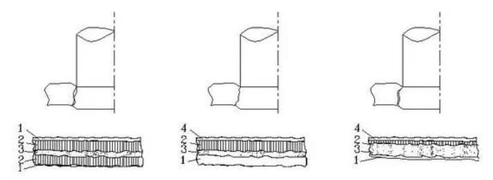
When blanking, if the clearance is too small, two distinct bright bands will appear on the section of the blanked part, and the burr at the upper end will be substantial. This is mainly due to the presence of an upper microcrack located at the edge of the punch, which is caused by the insufficient blanking clearance.
To prevent this, it is recommended to stagger the lower microcrack’s position at the edge of the die a certain distance away from the position where the upper microcrack occurs (refer to Fig. 2.3-2). By doing so, the upper and lower cracks will not be heavier than one line.
As the punch decreases, the material sandwiched between the two cracks will undergo a second shear, resulting in the formation of a second bright band and further elongation of the burr, leading to poor section quality.
On the other hand, if the clearance during blanking is too large, the upper microcrack will occur at the edge of the punch, and the position of the lower microcrack at the edge of the die will be staggered inward by a certain distance, so that the upper and lower cracks will not be heavier than one line.
The material sandwiched between the two cracks will be greatly stretched as the punch decreases, eventually tearing and breaking. This will result in a large fracture zone on the blanking section, making the bright zone smaller and the burr and taper larger. The collapse angle will increase, further deteriorating the section quality (refer to Fig. 2.3-4).
Based on the analysis, it can be concluded that even if an appropriate clearance value is chosen in the die design, it cannot ensure uniform distribution of the die clearance due to processing or assembly issues. As a result, it is unlikely to achieve the ideal section quality and a side with a small gap.
As previously noted, if the gap is too small, the section will exhibit the characteristic of a small gap, and if the gap is too large, the section will exhibit the characteristic of a large gap, which is particularly pronounced in dies without guide posts.
Therefore, it is important to pay attention to this during production.
3. Impact of clearance on other aspects
(1) Influence of blanking clearance on blanking dimensional accuracy
As previously discussed, both elastic and plastic deformations occur in metal parts during blanking. This means that elastic deformation must take place when plastic deformation is occurring.
Due to the elastic deformation of the material during blanking, there will be a recovery of this elastic deformation after the blanking process is completed. This recovery will result in a certain deviation between the actual size of the blanked part and the edge size of the punch and die (refer to Fig. 2.3-5).
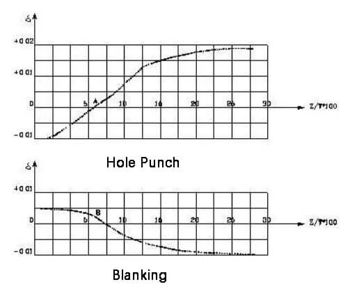
The vertical axis in the figure represents the elastic recovery of the blanked part, while the horizontal axis represents the relative clearance of the blanked part.
During blanking, as the blanking clearance increases, the size change curve of the blanked part reveals that the tensile deformation of the deformed metal also increases due to the increase in tensile stress at the deformed area.
After blanking, the compressed metal will recover elastically, leading to a reduction in the size of the blanked part. This rebound increases with the increase in blanking clearance.
As the blanking clearance decreases gradually, the size of the blanked part also decreases. When the clearance is reduced to a certain extent (point B in Fig. 2.3-5), the deformation properties of the blanked part also change. In addition to shear, there is extrusion deformation in the material, causing the deformation zone to transition from a tensile state to a compressive state.
After blanking, the compressed metal will recover its elasticity, causing the size of the blanking punch to be larger than the size of the die edge.
During punching, the same deformation process and elastic recovery principle apply, but the objects being measured are different. As a result, the conclusion is opposite to that of the blanked parts, meaning that the size of the punched parts increases with the increase in blanking clearance.
When the clearance value is less than a certain value (point A in Fig. 2.3-5), the size of the punched part will decrease, meaning that the size of the punched hole is smaller than the size of the punch.
It is important to note that the dimensional accuracy of blanked parts is primarily dependent on the design and machining accuracy of the blanking die. The above analysis was performed under a certain die manufacturing accuracy, and the impact of clearance on accuracy is much smaller compared to the die itself.
(2) The impact of blanking clearance on blanking force
The smaller the gap, the higher the compressive stress component in the material deformation zone, leading to greater material deformation resistance and an increased blanking force required during blanking. Conversely, the larger the gap, the higher the tensile stress component in the material deformation area, reducing material deformation resistance and the blanking force required during blanking.
However, practical experience shows that when the gap (on one side) gradually increases within the range of 5% to 2% of the material thickness, there is not a significant decrease in the blanking force.
(3) Influence of blanking clearance on unloading force and pushing force
The smaller the gap, the greater the elastic recovery of the material in the deformation zone, causing the punched part size to be smaller and the blanked part size to be larger. As a result, the unloading force and pushing force increase.
As the gap increases, due to the reduced elastic recovery of the material, the punched part size increases and the blanked part size decreases, making it easier to unload the material from the punch or push out the parts from the die opening.
Typically, when the gap (on one side) increases to 10% to 20% of the material thickness, the unloading force is close to zero.
(4) Influence of blanking clearance on die life
Practical experience has shown that among the many factors affecting die life, the blanking clearance is the most important.
During the blanking process, intense friction occurs between the punch and the punched hole and between the die and the blanked part. The smaller the gap, the more severe the friction, which is extremely detrimental to the service life of the die.
However, a larger clearance will reduce the friction between the edge of the punch and the die and the material, and can mitigate the adverse effects of uneven clearance caused by manufacturing and installation errors of the die, thereby improving its service life.
4. Determination of clearance value
The term “reasonable gap” refers to a gap that allows for satisfactory workpiece section quality, high dimensional accuracy, minimizes the blanking force (unloading force and pushing force), and results in a long service life for the die when used for blanking.
However, it is not possible to simultaneously meet all of these requirements by using a single gap value. Therefore, in production, it is necessary to comprehensively consider the influence of various factors and select an appropriate gap range as a reasonable gap based on the specific requirements of the parts.
The upper limit of this range represents the maximum reasonable gap and the lower limit represents the minimum reasonable gap. In other words, a reasonable gap refers to a range of values.
When designing the die, it is recommended to select the gap based on the specific requirements of the parts and production, following the following principles.
(1) When there are no special requirements for the cross-section quality of the counter-cut part, a larger clearance value can be selected to improve the service life of the die and reduce the blanking force for greater economic benefits.
(2) When there are high requirements for the cross-section quality of counter-cut parts, a smaller clearance value should be selected.
(3) When designing the cutting edge size of the blanking die, it should be taken into consideration that the die will experience wear during use, which will increase the cutting edge gap. The cutting edge size should be calculated based on the minimum gap value.
In practice, the die industry has accumulated a large number of empirical values for stamped parts with different thicknesses of various stamping materials, so the theoretical gap calculation method is only used as a reference.