Let’s cut to the chase and go straight to the question:
Figure 1 depicts the parallel gear of a megawatt model from a company. The gear is made of 18CrNiMo7-6 steel and requires carburizing and quenching. The gear tooth modulus is 10mm.
With an outer diameter of 1680mm, a tooth width of 180mm, and an inner hole diameter of 500mm, the gear is designed with a thin web.
Please refer to Table 1 for the technical specifications of the heat treatment process.
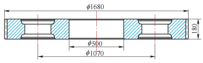
Fig. 1 Overall Dimension of Gear
Table 1 Technical Requirements for Heat Treatment of 18CrNiMo7-6 Steel Gear
| Effective hardened case depth/mm | Surface hardness HRC | Core hardness HRC | carbide | Martensite | Retained austenite (%) | Cardiac tissue | IGO/mm |
| 2.9~3.9 | 58~64 | ≥30 | ISO 6336:5MQgrade | Fine needlelike | ≤30 | No massive ferrite | ≤0.05 |
1. Process route
The process flow of gear processing is forging → normalizing → rough turning → hobbing → chamfering → carburizing and quenching → shot peening → semi finishing turning → finishing turning → keyway → assembly → boring → gear grinding → warehousing.
During the trial production process, the gear underwent carburizing, high temperature tempering, quenching, low temperature tempering, and shot peening. However, during the gear grinding stage, it was discovered that the gear had significant distortion.
Additionally, after trial grinding, the normal of the part was found to be below the required value.
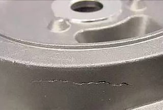
Furthermore, there were noticeable grinding marks at the root of the gear, leading to the decision to scrap the part.
2. Trial production process and deformation mechanism analysis
At the beginning of the trial production phase, it was determined that parts with serial number H1 would be used for trial production based on the actual conditions on site. This was due to the fact that the gear had a diameter width ratio of 9.3, the web plate was thin, the weight reduction holes were large, and the parts were prone to warping deformation.
The heat treatment process for the trial production is illustrated in Figure 2. The process utilized was “carburizing – high recovery – quenching – low recovery.” The temperature was raised using a step heating method and the quenching was performed using a salt bath method.
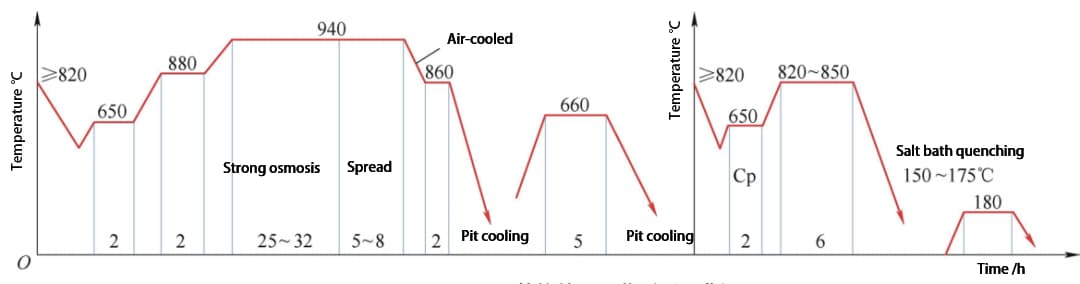
Fig. 2 Heat Treatment Process of H1 Parts (Original Process)
The parts are installed flatly using the tooling of a 2 meter deep well type carburizing furnace. To make the operation easier, a chassis tooling with 8 intervals was selected and 4 fan-shaped honeycomb plates were positioned at intervals, as depicted in Figure 3.
Following high temperature tempering, the method of quenching charging was changed to hanging, with the hanging position being the inner hole of the part, as shown in Figure 4.
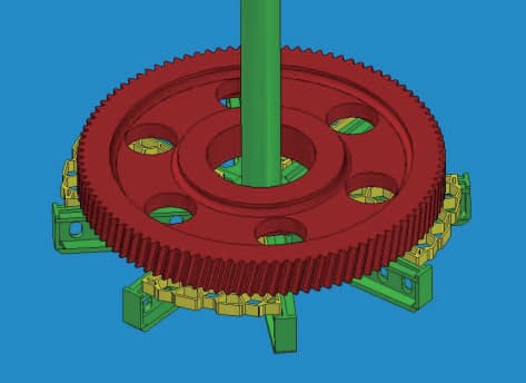
Fig. 3 H1 Parts Carburizing Charging
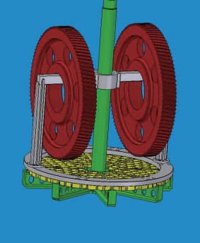
Fig. 4 H1 Parts Quenching Charging
After undergoing heat treatment, the parts underwent testing of their physical and chemical indicators, which were found to meet the qualifications.
During the gear grinding process, it was reported that there was significant distortion in the teeth.
The average normal of the parts after trial grinding was found to be 604.74mm, which falls below the required lower limit of 605.014mm.
Due to the presence of grinding steps on some gear roots, these parts were considered scrap.
To identify the cause of the deformation in the parts, the alignment data of the H1 part during gear grinding was collected and analyzed.
1)Review the grinding gear alignment tolerance report for the tooth section. Ensure that multiple tooth profiles intersect correctly in the tooth direction and that the overall tooth direction is not significantly distorted.
2)Compare the high and low points of the grinding tooth alignment on both the left and right tooth surfaces. Present the findings using a radar chart, as illustrated in Figure 5.
Analysis reveals that the greatest amount of distortion takes place at tooth positions 57 to 82, while the deformation at other positions is within acceptable limits.
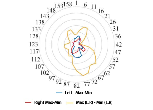
Fig. 5 Deformation of left and right tooth surfaces of H1 part
3)Upon comparing the grinding allowance distribution of the left and right tooth surfaces, no significant eccentricity was found during gear grinding. The requirements for turning the inner hole and end face datum were met.
4)The grinding tooth alignment data of the left and right tooth surfaces were averaged, as shown in Fig. 6. The analysis revealed an evident elliptical shape in the pitch circle of the part, with a pear-shaped trend and an elliptical amount of approximately 0.18mm.
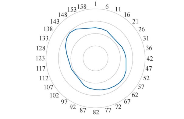
Fig. 6 Average Wear of Left and Right Tooth Surfaces of H1 Parts
Based on the analysis of the grinding and centering data of H1 parts, it is currently impossible to determine whether the tooth deformation of the parts is due to end-face warping or tooth distortion.
The parts exhibit an elliptical trend and have a pear-shaped profile.
Although it is not possible to determine whether a specific position is related to the hanging, it can be inferred from the single-point hanging that the position of the pear handle (near the 148th tooth) is where the tooling contacts and where the bulge is the largest.
The position of the maximum deformation of the left and right tooth surfaces does not follow a significant pattern, but the deformation trend is the largest near the elliptical pear-shaped tail (i.e., the lower part of the suspension).
Based on the above analysis, the primary causes of workpiece deformation are:
1)The random distribution of tooth deformation in parts is related to the carburizing process, including factors such as heating rate, carburizing temperature, and others.
2)During carburizing, only four honeycomb discs are placed at intervals. Creep can occur during carburizing, resulting in warping deformation of the end face, which can cause tooth direction to cross.
3)During hang-up quenching, creep can occur during quenching heating, causing deformation that is mainly manifested as an ellipse caused by hanging up during quenching.
4)When parts are quenched in a salt bath, the first contact position shows a greater tendency towards deformation. This position comes into contact with the salt bath first and is closer to the bottom agitator, resulting in a faster relative flow speed of fluid.
3. Process improvement
Based on the analysis of H1 part, the key factor causing the deformation of the part could not be identified.
As a first step towards improvement, the heat treatment process was modified. The deformation of the gear after carburizing was tracked to determine whether significant heat treatment deformation had occurred during the carburizing stage.
The test part’s serial number is H2, and the carburizing charging method is the same as that used for H1.
3.1 Improvement of carburizing process
To minimize the thermal stress and distortion caused during carburization, the process has been updated as illustrated in Fig. 7. The new approach involves lowering the initial temperature of the parts as they enter the furnace, extending the isothermal period at both 650℃ and 880℃, expanding the isothermal range at 770℃, and decreasing the carburizing temperature at the highly carburized section.
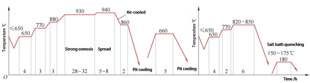
Fig. 7 Heat Treatment Process of H2 Parts (Improved Process)
3.2 Carburizing charging improvement
To analyze the gear end face warpage during carburization and its impact on the tooth profile for subsequent gear grinding alignment, H2 parts replicated the charging method of H1 gears in the initial production run. They marked the end face after high-temperature tempering and pre-turned the end face datum before grinding the gear alignment on the gear grinding machine.
However, during the benchmark turning, they discovered a significant runout in the end face, as shown in Fig. 8. The honeycomb panel supported positions all exhibited high points, while those without padding showed low points. The difference between high points was approximately 0.2mm, and the difference between low points was about 0.25mm.
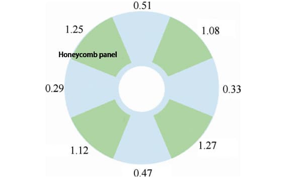
Fig. 8 Axial circular runout of H2 parts after carburizing
The gear teeth alignment data indicates that the part’s tooth direction has significantly crossed, but there are no visible ellipses. The maximum difference between the high and low points on the left and right tooth surfaces occurs where the honeycomb plate is not padded.
Further exploration of the carburizing charging mode for H2 parts revealed that excessive axial circular runout caused by creep during carburizing is a major factor contributing to part deformation. To minimize the axial circular runout of the gear after carburizing, the number of bottom supporting honeycomb plates has been increased from 4 to 8, as depicted in Fig. 9.
This modification has enabled control of the axial circular runout of the parts after carburizing and quenching to below 0.52mm.
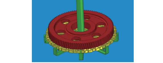
Fig. 9 Carburizing charging after improvement
3.3 Quenching charging improvement
In summary, the rapid cooling speed at approximately 1/4 of the lower part of the gear is one of the factors that contribute to gear deformation. Therefore, the quenching process needs to be adjusted. For testing, carburized H2 parts were used, and a mesh damping tool was added to the bottom tray to reduce the relative fluid flow speed at the lower end of the gear during quenching.
To verify if the relevant physical and chemical indicators were affected, tooth-shaped samples of the same specification were carried with the furnace. Table 2 shows the test results for the tooth-shaped sample carried with the furnace after quenching, which were acceptable.
Compared to H1, the deformation of H2 parts after quenching was reduced to some extent, and the common normal of the parts after gear grinding was 0.03 mm less than the lower limit of the standard value. Therefore, the parts can be used with some concessions.
Table 2 Heat Treatment Results of H2 Parts
| Project | Requirement | Measurement | |||||
| Effective hardened case depth/mm | 2.9~3.9 | 3.39 | 3.46 | ||||
| Surface hardness HRC | 58~64 | 60.26 | 59.62 | ||||
| Core hardness HRC | ≥30 | 38 | |||||
| Carbide | ISO 6336:5 | MQ grade | Diffusion | ||||
| Martensite | Fine needlelike | Fine needlelike | |||||
| Retained austenite (%) | ≤30 | 15 | |||||
| Cardiac tissue | No massive ferrite | No massive ferrite | |||||
| IGO | /mm | ≤0.05 | 0.025 | ||||
3.4 Optimization verification
During the production of parts with serial numbers H3 and H4, both the carburizing process shown in Fig. 8 and the flat charging method of fully laying honeycomb plates at the bottom during carburizing (as shown in Fig. 9) are used. Additionally, during hanging quenching charging, mesh damping tooling is added to the chassis to improve the deformation of parts after carburizing and quenching.
Fig. 10 and Fig. 11 show the radar chart of the grinding tooth alignment data of H3 parts, with the position of No. 109 tooth being the fulcrum position when hanging. It can be seen from the figure that the ellipse is basically consistent with H1 parts. Moreover, the overall deformation and the deformation of the first contact area with the liquid level during quenching are significantly reduced.
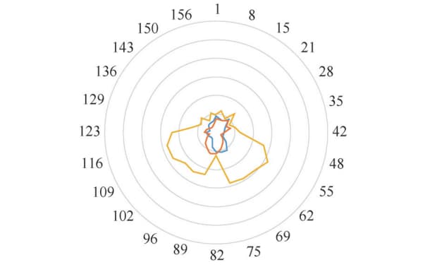
Fig. 10 Left and right tooth surfaces of H3 parts deformed
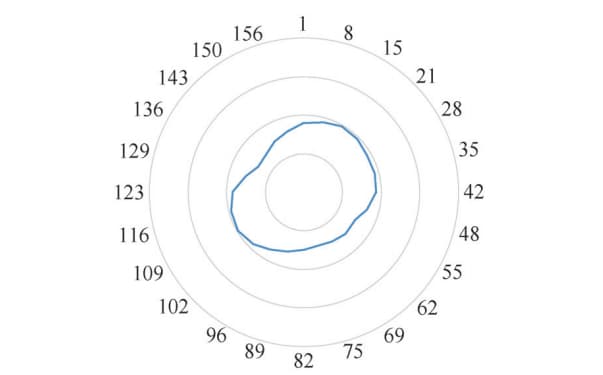
Fig. 11 Average Wear of Left and Right Tooth Surfaces of H3 Parts
Table 3 and Fig. 12 show the summary of deformation of parts after heat treatment with different carburizing processes and charging methods.
It can be seen from the comparison that the tooth distortion of the part is reduced by about 40% after the improved carburizing process, optimized carburizing and quenching charging mode are adopted.
Table 3 Influence of Different Charging and Heat Treatment Processes on Gear Deformation
| Part number | H1 | H2 | H3 | H4 |
| Carburizing charging | Flat-mounted 4 honeycomb panels | Flat mounted 8 honeycomb panels | ||
| Quenching charging | Hanging and placing undamped tooling | Hanging damping tooling | Hanging damping tooling | |
| Carburizing and quenching process | the original process | Improve process | Improve process | |
| Ellipse/mm | 0.18 | 0.14 | 0.14 | 0.15 |
| Axial circular runout/mm | — | 1.06 | 0.52 | 0.25 |
| Size of common normal after grinding/mm | 604.74 | 604.98 | 605.04 | 605.06 |
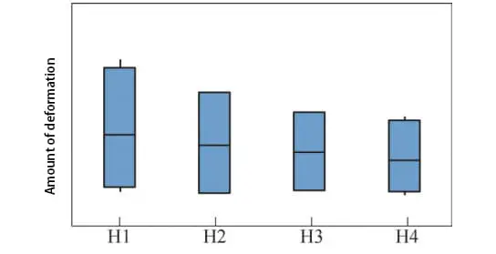
Fig. 12 Box and line diagram of different charging methods and heat treatment process deformation
3.5 Mass production
Based on the experience gained during the prototype stage, the tooling for quenching and hanging has been re-optimized from the original single-point support to a two-point support system. Additionally, the ellipse of the part has been reduced from the original range of 0.14-0.18mm to 0.05-0.10mm.
Regarding the fit for cold and hot processing, the common normal of the part shrinks by approximately 0.25mm after carburizing and quenching. Therefore, a 0.25mm hobbing common normal allowance should be compensated before heat treatment.
As a result of these improvements, all 30 gears produced in a small batch are now qualified.
4. Conclusion
1)For flat gears, it is important to ensure that all points on the end face are evenly supported during carburizing. To reduce the end face warping deformation caused by creep during horizontal carburization, the spacing of the original four honeycomb discs can be changed to the full placement of eight honeycomb plates.
2)The hanging tooling is utilized for quenching. By adding a mesh damping tooling at the bottom of the quenching tray, the relative flow rate of the quenching cooling medium and parts is reduced. This results in a significant reduction of tooth deformation in the lower area of the hanging tooling.
3)To reduce stress and high-temperature creep during heat treatment of flat gears, the carburizing temperature can be lowered, the temperature rise step can be increased, the isothermal time can be extended, and the carburizing temperature can be reduced.
4)By improving the heat treatment charging and process, the warp deformation of the gear end face has been reduced from 1.06mm to 0.52mm. The pitch circle runout has been reduced from 0.18mm to 0.1mm, and tooth distortion has been reduced by approximately 40%. These improvements have resulted in a 100% qualification rate for small batch production.