The gear is the most crucial component in the gearbox. During operation, the tooth surface endures the contact stress, while the tooth root bears the bending stress. Hence, the failure forms of gears are primarily categorized into pitting corrosion and peeling due to tooth surface fatigue and tooth fracture caused by tooth root fatigue.
Carburizing and quenching are the most widely used and developed processes for high-speed and heavy-duty gears.
This method can simultaneously improve the tooth surface contact fatigue strength and tooth root bending fatigue strength. However, the carburizing and quenching process is complicated, and various types of defects may occur during heat treatment, which can lead to early gear failure.
During the fatigue life test of a newly developed transmission assembly by our company, one of the gears broke.
The design specifications require the gear material to be 8620H. It underwent carburizing and quenching and was then tempered at a low temperature. The effective hardened layer depth is 0.8 to 1.3mm, surface hardness is 58 to 64HRC, and the core hardness is 30 to 45HRC.
To determine the cause of tooth fracture, we conducted tests and analyzed the fracture morphology, material, and heat treatment quality.
1. Physical and chemical testing and analysis
(1) Macro observation
Figure 1 illustrates the overall appearance of the failed gear. Several teeth are broken at the root, and the number of broken teeth exceeds half of the total number of teeth.
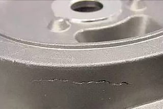
The macro morphology of the fracture is presented in Figure 2.
Based on the fracture morphology, the majority of fractures exhibit obvious fatigue fracture characteristics. The fracture source is located at the root of the tooth.
The smooth and outwardly radiating fatigue expansion area accounts for approximately 1/3 to 1/2 of the total root area.
The fracture surface of the transient fracture area is rough and dark gray.
Apart from fatigue fractures, some gear fractures show no fatigue fracture characteristics and result from one-time overload fractures.

Fig. 1 Overall View of Broken Teeth

Fig. 2 Fracture morphology
(2) Fractography
After sampling, the fracture morphology was observed using a scanning electron microscope.
Figure 3 displays the appearance of the crack source.
The crack source is situated at the tooth root. From the figure, it can be seen that the fracture’s crack source is not converging to a point but is linear.
The surface of the crack source is smooth due to repeated friction and extrusion.
Upon further examination, black abnormal structures are visible at the crack source (refer to Fig. 4).
Observation of the microscopic morphology of the fatigue growth zone at 1000 times magnification is presented in Fig. 5.
At high magnification, fatigue striations and radial prisms can be seen.
Figure 6 illustrates that the appearance of the transient fracture zone is dimple+quasi cleavage fracture, indicating good toughness of the gear center.

Fig. 3 Crack Source

Fig. 4 Black Structure of Crack Source

Fig. 5 Fatigue Propagation Fracture
Fig. 6 Morphology of dimple+quasi cleavage in transient fracture zone
(3) Gear material inspection
Samples were taken from the failed gear for chemical composition analysis, and the results are presented in Table 1.
According to the analysis, the chemical composition of the gear meets the technical requirements of SAEJ1268 standard for 8620H steel.
Table 1 Test Results of Chemical Composition (Mass Fraction) (%)
| Element | C | S | P | Si | Mn | Cr | Ni | Mo | Cu |
| Standard value | 0.17~0.23 | ≤0.040 | ≤0.030 | 0.15~-0.35 | 0.60~0.95 | 0.35~0.65 | 0.35~0.75 | 0.15~0.25 | ≤0.35 |
| Detection value | 0.22 | 0.017 | 0.010 | 0.28 | 0.87 | 0.58 | 0.45 | 0.18 | 0.086 |
(4) Quality inspection of gear heat treatment
To test the heat treatment quality, take the unbroken gear next to the broken one.
The surface hardness is 61 HRC, and the core hardness is 45 HRC.
The surface structure comprises martensite and retained austenite, with a retained austenite content of approximately 15%. The center consists of lath martensite and a small amount of bainite.
The effective hardened layer depth at 1/2 tooth height is 1.01 mm.
The gear has undergone carburization and quenching, and all heat treatment indexes comply with the design requirements specified in the drawing.
To prepare a sample, use a precision cutting machine to cut the gear along the middle of the tooth width, and then examine the metallographic structure of the tooth root on the cutting surface using a metallographic microscope.
In the absence of corrosion (refer to Fig. 7), serious black tissues can be observed at the root of the tooth, distributed in a network, with an average depth of around 20 μm. The individual depth of the black tissues reaches up to 30 μm.
A straight crack originates from the black tissue of the tooth root and extends inwards perpendicular to the root of the tooth.
Observation after corrosion (refer to Fig. 8) reveals that normal carburized and quenched structures exist on both sides of the crack.
The metallographic observation of the two end faces of the sample’s root shows no signs of cracks.
Based on the above inspection, it is inferred that the observed cracks are generated during use, suggesting that the tested teeth have developed fatigue cracks that have expanded, and the test was halted before the fracture occurred.
If the test were to continue, it is expected that the fracture would occur.
According to the metallographic analysis, the crack is closely associated with the black tissue at the tooth root.
-No-corrosion.jpg)
Fig. 7 Black tissue and crack at tooth root (500 ×) No corrosion

Fig. 8 Structure on both sides of crack (50 ×) 4% nitric acid alcohol solution
2. Analysis and discussion
Most of the broken teeth on the failed gear are due to fatigue fracture, with the cracks starting at the root of the middle part of the tooth width.
Through metallographic observation and scanning electron microscope observations of the tooth root, it is evident that the black tissue becomes the source of crack initiation during gear use.
As the number of operations increases, the crack source expands, eventually leading to gear fracture failure.
After carburizing, the surface microstructure of alloy steel often appears dotted, reticulated or banded black microstructures distributed along the grain boundary.
The reason for this type of structure is that oxygen in the carburizing medium diffuses into the steel, forming oxides of chromium, manganese, titanium, silicon, and other elements on the grain boundary. This results in depleted alloy elements at the grain boundary, causing a decrease in local hardenability and the appearance of black austenitic decomposition products, such as troostite.
Research conducted both domestically and internationally indicates that the presence of black tissue significantly reduces the surface hardness, bending fatigue strength, and contact fatigue strength of parts, negatively impacting their service life.
As such, many well-known vehicle manufacturers both domestically and abroad have established specific requirements for the depth of black tissue. For instance, German automakers such as Benz and BMW require that the depth of black tissue must not exceed 3μm.
Additionally, the FAW Group is planning to reduce the depth of black tissue from less than 20μm to less than 3μm.
3. Suggestions for improvement
Through the inspection and analysis above, it is evident that the depth of the black structure in the surface metallographic structure of carburized and quenched parts requires strict control. The control of the black tissue primarily begins with the following two aspects:
- Improving the purity of the carburizing gas and reducing the oxygen content. This can be achieved by strictly controlling the purity and water content of carburizing agents, such as methanol and acetone, and regulating the amount of air.
- Adopting more intense quenching and cooling methods, such as using a quenching medium with stronger quenching and cooling performance or employing faster quenching, cooling, and stirring.