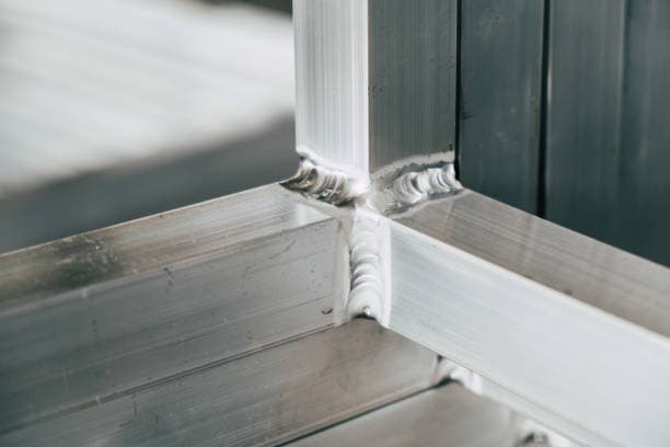
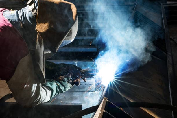
Welding characteristics of aluminum and aluminum alloy
Aluminum is easily oxidized in the air and during welding, and the aluminum oxide (Al2O3) generated has a high melting point, is very stable, and is not easy to remove.
It hinders the melting and fusion of the base metal.
The specific gravity of the oxide film is large, so it is not easy to float out of the surface, and it is easy to generate defects such as slag inclusion, incomplete fusion, incomplete penetration, etc.
The oxide film on the surface of aluminum and the absorption of a large amount of water are easy to cause porosity in the weld.
Before welding, the surface shall be strictly cleaned by chemical or mechanical methods to remove the oxide film on the surface.
Strengthen protection during welding to prevent oxidation.
During argon tungsten arc welding, AC power supply is selected to remove oxide film through “cathode cleaning.
During gas welding, use the flux to remove the oxide film.
When welding thick plates, the welding heat can be increased, for example, the heat of helium arc is high, helium or argon helium mixed gas is used for protection, or large standard MIG welding is used.
Under the condition of DC positive connection, “cathodic cleaning” is not required.
The thermal conductivity and specific heat capacity of aluminum and aluminum alloy are about twice as much as those of carbon steel and low alloy steel.
The thermal conductivity of aluminum is more than ten times that of austenitic stainless steel.
In the welding process, a large amount of heat can be quickly transmitted to the interior of the base metal.
Therefore, when welding aluminum and aluminum alloys, more heat is needlessly consumed in other parts of the metal, in addition to the molten metal pool.
The consumption of such useless energy is more significant than that of steel welding.
In order to obtain high-quality welding joints, energy with concentrated energy and large power should be used as much as possible.
Sometimes, technological measures such as preheating can also be adopted.
The linear expansion coefficient of aluminum and aluminum alloy is about twice that of carbon steel and low alloy steel.
The volume shrinkage of aluminum during solidification is large, and the deformation and stress of weldments are large.
Therefore, measures to prevent welding deformation should be taken.
Shrinkage cavity, shrinkage porosity, hot crack and high internal stress are easily produced during solidification of aluminum welding pool.
In production, the measures of adjusting the composition of welding wire and welding process can be taken to prevent hot cracks.
If corrosion resistance is allowed, aluminum silicon alloy welding wire can be used to weld aluminum alloy except aluminum magnesium alloy.
When the silicon content in aluminum silicon alloy is 0.5%, the hot cracking tendency is larger.
With the increase of silicon content, the crystallization temperature range of the alloy becomes smaller, the fluidity is significantly improved, the shrinkage is reduced, and the hot cracking tendency is also reduced.
According to the production experience, when the silicon content is 5%~6%, no hot cracking will occur, so the use of SAlSi bars (silicon content 4.5%~6%) welding wire will have better crack resistance.
Aluminum has a strong ability to reflect light and heat.
When solid and liquid are transferred, there is no obvious color change.
It is difficult to judge during welding operation.
High temperature aluminum has low strength, and it is difficult to support the molten pool and easy to weld through.
Aluminum and aluminum alloys can dissolve a large amount of hydrogen in liquid state, but almost no hydrogen in solid state.
In the process of solidification and rapid cooling of welding pool, hydrogen can not overflow in time, and hydrogen pores are easily formed.
The moisture in the arc column atmosphere and the moisture absorbed by the oxide film on the surface of welding materials and base metal are important sources of hydrogen in the weld.
Related reading: Aluminum Alloy Welding Method and Material Selection
Therefore, the source of hydrogen should be strictly controlled to prevent the formation of pores.
Alloy elements are easy to evaporate and burn, which will reduce the performance of the weld.
If the base metal is deformation strengthened or solution aging strengthened, the welding heat will reduce the strength of the heat affected zone.
Aluminum is a face centered cubic lattice without isomers.
There is no phase transformation during heating and cooling.
The weld grains are easy to coarsen and cannot be refined through phase transformation.
Welding method
Almost all kinds of welding methods can be used to weld aluminum and aluminum alloys, but aluminum and aluminum alloys have different adaptability to various welding methods, and various welding methods have their own application occasions.
Resistance welding
Generally, aluminum alloy resistance butt welding (spot welding) can only be used for overlap welding of plates with a thickness of less than 5mm, or between bars with a thickness of less than 10mm.
The advantages are low welding cost, high welding efficiency and easier integration into automatic production lines.
For example, automobile manufacturing is widely used.
The limitation is that the thickness of welding is limited, and different electrodes should be made for different products and structures.
Argon arc welding
Manual argon tungsten arc welding is mainly used for welding aluminum alloy sheet (thickness<6mm) structure.
Due to the protective effect of argon and the crushing effect of argon ion on aluminum alloy oxide film, argon arc welding can avoid welding powder, thus avoiding the corrosion of welding residues on the joint.
Therefore, after argon arc welding, cleaning is not required, and the joint form can also be unrestricted.
In addition, the argon flow scouring the welding area during welding can significantly cool the welded joint, thus improving the structure and performance of the joint and reducing the deformation of the weldment.
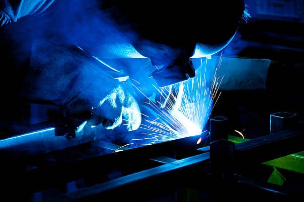
Gas shielded welding
In general, it is difficult to master the single-sided welding and double-sided forming of aluminum alloy with gas shielded welding.
Related reading: Shielding Gas for Laser Welding
If the butt plates have gaps, it is easy to weld through, and the back penetration of welds without gaps is not easy to control.
Generally, AC argon arc welding is also used for aluminum alloy welding in China, but for thicker plates, the efficiency of argon arc welding will be very low.
At present, molten electrode pulse gas shielded aluminum alloy welding is only used in some examination items, and most butt plate welding is overhead welding, mainly used for the welding of aluminum alloy car body and frame of EMUs.
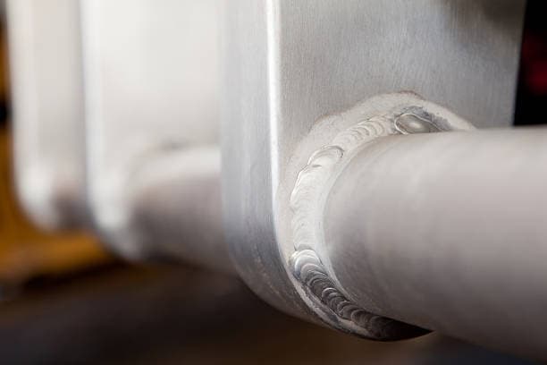
Friction welding
The friction stir welding seam of aluminum alloy is formed through plastic deformation and dynamic recrystallization.
The grain in the weld zone is fine, without fusion welding dendrites, and the microstructure is fine.
The heat affected zone is narrower than that in fusion welding, and there are no alloy element burning loss, cracks, pores and other defects. The comprehensive performance is good.
Compared with the traditional fusion welding method, it has no spatter, smoke and dust, does not need to add welding wire and shielding gas, and has good joint performance.
Due to the solid phase welding process, the low heating temperature makes the welding deformation small.
The disadvantage is that the welding speed is slow and the process is not mature enough.
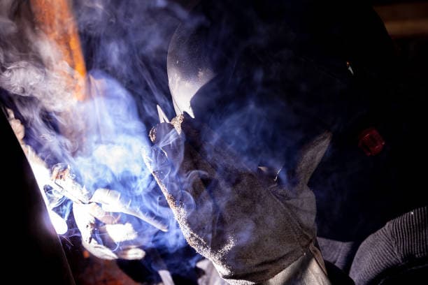
Laser welding
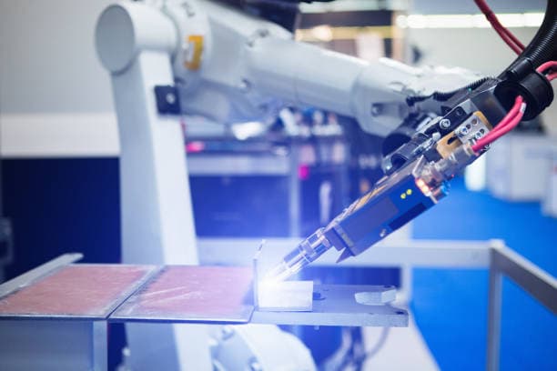
Laser welding technology of aluminum alloy is a new technology developed in recent ten years.
Related reading: Laser Welding: The Basic Guide
Compared with the traditional welding technology, it has the characteristics of strong function, high reliability, no need for vacuum conditions and high efficiency.
It is characterized by high power density, low total heat input, large penetration of the same heat input, small heat affected zone, small welding deformation, high speed, easy industrial automation, etc.
Its disadvantage is that when welding aluminum alloy, energy cannot be fully absorbed, resulting in large waste and high equipment procurement cost.