The fillet weld is the most commonly used welding technique for splicing steel structures during the welding process. As a result, welders often encounter various types of fillet welds, each with different standards.
So, how can we ensure that we weld fillet welds properly and produce high-quality fillet welds that meet the necessary requirements? Today, I would like to provide a brief introduction to this topic.
1. Selection of base metal
Let’s take the test panel of size 200 made of Q355 as an example for a brief introduction.
2. Selection of welding materials
Welding material: E5015 (J507) welding rod shall be used, the drying temperature shall be 350 ℃, the heat preservation shall be 1 hour, and the welding wire shall comply with the national standard ER50-6 (American standard ER70S-6).
3. Cleaning before welding
For fillet welding, it is essential to clean both sides of the weld within a 15-20mm range. The plate surface should be free from any oxide film, rust, oil, or water, which can be removed either by using a grinding wheel or through chemical treatment.
4. Assembly point fixing
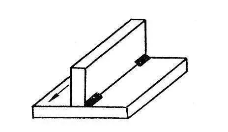
Ideally, the weld gap for fillet welding should be kept as minimal as possible. Spot-fixing is usually performed on the back of the plate, with the length of the spot-fixing being around 10mm. Typically, two or three points are sufficient for fixing, as illustrated in the diagram below:
5. Welding parameters
|
Weld bead distribution |
Welding level |
Electrode diameter mm |
Welding current A |
Welding speed mms |
Heat input KJmm |
|
|
a=7mm |
1 |
3.2 |
120-140 |
/ |
/ |
/ |
|
2, 3 |
4.0 |
160-180 |
/ |
/ |
/ |
6. Welding operation
Backing weld
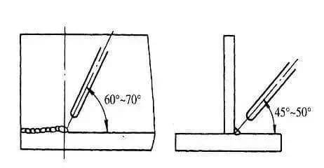
1.1 Electrode angle and electrode handling method
The electrode angle for root flat fillet welding is illustrated in the figure. To ensure proper welding, strike the arc on the left side of the test plate and perform short arc welding.
Use a straight electrode to weld to the right and align the arc with the top angle of the root. Depress the arc to ensure that the top angle and the two side plates are fused.
When performing backing welding, use the straight line electrode moving method for swinging. Fast welding without swinging can also achieve the required penetration.
During the start and end of a welding operation, it is common to experience magnetic bias blowing, which can negatively impact the weld quality. To mitigate this, it is necessary to adjust the angle of the welding rod appropriately.
Typically, pointing the arc towards the molten pool can help control the magnetic bias blowing and ensure a higher quality weld.
As shown in the figure.
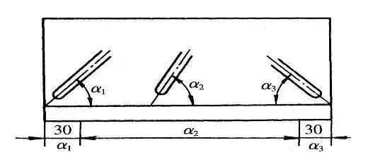
1.2 Weld bead joint
The arc should be started 10mm in front of the crater on the joint. As the elongated arc moves quickly towards the crater, fill the crater along its shape, and then proceed with normal welding.

Cover welding
Prior to welding, it is important to remove any welding slag and spatter from the root pass to prevent slag inclusion defects.
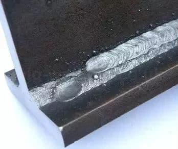
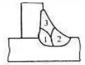
The cover shall be welded twice, starting with the lower weld bead followed by the upper weld bead.
When welding the lower weld bead, the arc should be aligned with the lower edge of the root weld bead, and the electrode should be moved in a straight line with an electrode angle greater than 45°.
When welding the upper weld bead, the arc should be aligned with the upper edge of the root weld bead. The electrode can swing laterally while moving in a straight line, with an electrode angle less than 45°, as shown in the figure below:


Schematic diagram of each layer of pavement
Representation of fillet size
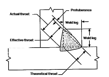
Projection fillet weld
Recessed fillet weld
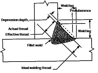
Theoretical throat: the vertical distance from the joint root to the bevel in the largest inscribed right triangle drawn in the fillet weld profile.
Effective throat: the minimum distance from the fillet weld surface to the weld root minus the raised part.
Actual throat: the shortest distance between the fillet weld surface and the weld root.
For concave fillet weld, since there is no convex part, the effective throat is equal to the actual throat.
Leg size: the distance from the root of the joint to the toe of the fillet weld.
Weld toe: the intersection point between the weld surface and the base metal.
When determining the size of a fillet weld, it is important to determine whether the weld is convex or concave.
Convex fillet welds have a slightly bulging weld surface, which is related to the height of the bulge.
The bulge height of a fillet weld is equivalent to the reinforcement height of a groove weld.
If there is a dent in the weld, it means that the weld surface is dished.
For both convex and concave shapes, the weld size of a fillet weld with equal leg height is expressed as “the straight edge of the largest isosceles right triangle obtained in the fillet weld profile (two legs are equal in length).”
As a result, the weld leg of a convex fillet weld is equal to the weld size, while the weld leg size of a concave fillet weld is slightly smaller than its weld leg length.