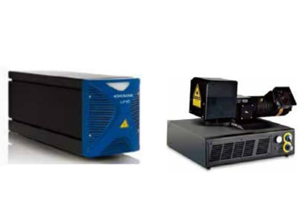
A laser displacement sensor is a measuring instrument that uses laser technology to measure the position, displacement, and other changes of a measured object. It consists of a laser, a laser detector, and a measuring circuit.
This type of sensor offers accurate, non-contact measurements and is capable of measuring displacement, thickness, vibration, distance, diameter, and other precise geometric measurements. The laser used in the sensor has excellent straightness characteristics.
Compared to ultrasonic sensors, laser displacement sensors have a higher level of accuracy. However, the laser generating device is relatively complex and large, limiting the range of applications for laser displacement sensors.
1. Basic principles
A laser displacement sensor is a device that accurately measures the position, displacement, and other changes of an object without physical contact. It is widely used to detect displacement, thickness, vibration, distance, diameter, and other geometric properties of objects.
The principle of a laser displacement sensor is divided into two methods: laser triangulation and laser echo analysis. The laser triangulation method is typically used for high-precision, short-distance measurements, while the laser echo analysis method is suited for long-distance measurements.
The following is a brief introduction to these two measurement methods of the laser displacement sensor principle.
The beam is processed by analog and digital electronic processing at the position of the receiving element. After internal micro-processing and analysis, the corresponding output value is calculated, and the output value is used to adjust the emission of light to the object. This adjusts the displacement distance of the beam of light.
2. Purpose
1. Length measurement
To measure a component, place it in the designated position on the conveyor belt. The laser sensor, triggered by the laser scanner, will then detect and measure the component, finally determining its length.
2. Uniformity Inspection
Place multiple laser sensors in the direction of tilt of the workpiece to be measured and have one sensor directly output the measurement value. Furthermore, a software can be utilized to calculate the measurement value and display the result based on the received signal or data.
3. Inspection of electronic components
Use two laser scanners to position the components being measured between them and then obtain the data through the sensors to assess the accuracy and completeness of the component’s dimensions.
3. Triangulation
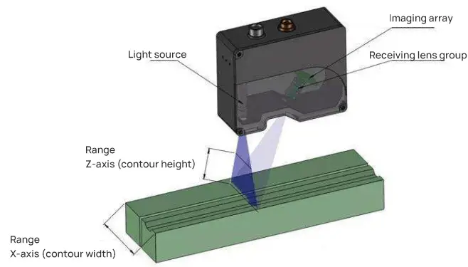
The laser transmitter projects a visible red laser onto the surface of the object being measured through a lens. The scattered laser light from the object’s surface then passes through the receiver lens and is detected by the internal CCD linear camera.
Based on the distance from the object, the CCD linear camera detects the light spot at different angles. Using this angle and the known distance between the laser and the camera, the digital signal processor calculates the distance between the sensor and the object.
The position of the beam in the receiving element is then processed by analog and digital circuits, and the corresponding output value is calculated by the microprocessor. The standard data signal is output proportionally in the analog window set by the user. If switching value output is selected, it will be activated within the set window and shut off outside of it.
Both the analog and switching outputs can have separate detection windows. The laser displacement sensor, using triangulation, can achieve maximum linearity of 1um with a resolution of 0.1um. For example, the ZLDS100 type sensor boasts a high resolution of 0.01%, high linearity of 0.1%, fast response of 9.4KHz, and the ability to perform in harsh environments.
4. Echo analysis
The laser displacement sensor utilizes the principle of echo analysis to accurately measure distance. The sensor is comprised of a processor unit, echo processing unit, laser transmitter, laser receiver, and other components.
Each second, the laser transmitter sends one million laser pulses to the object being detected, which then returns to the receiver. The processor calculates the time it takes for the laser pulse to reach the object and return, allowing for the calculation of the distance value.
This value is determined by taking the average of thousands of measurements, using the pulse time method. Although the laser echo analysis method is suitable for long-distance detection, it has a lower accuracy compared to the laser triangulation method. The farthest detection distance it can reach is 250 meters.
5. Measurement application
Laser displacement sensors are widely used to measure various physical quantities including length, distance, vibration, speed, orientation, and more. These sensors have also found applications in flaw detection and monitoring of air pollutants.
1. Size measurement:
- Recognition of the position of micro components
- Detection of components presence on the conveyor belt
- Detection of overlapping and coverage of materials
- Control of manipulator’s position (tool center point)
- Monitoring of device status
- Detection of device’s position using small openings
- Monitoring of liquid levels
- Measurement of thickness
- Analysis of vibrations
- Measurement of collision tests
- Testing related to automobiles, etc.
2. Thickness measurement of metal sheet and sheet:
A laser sensor is used to measure the thickness of metal sheets.
Detection of changes in thickness can assist in identifying wrinkles, small holes, or overlaps, thereby preventing machine failure.
3. Measure the cylinder barrel and measure at the same time:
- Angle
- Length
- Eccentricity of the inner and outer diameter
- Conicity
- Concentricity
- Surface profile.
4. Length measurement:
Place the component to be measured in the designated position on the conveyor belt. The laser sensor will then detect the component and simultaneously measure it using the triggered laser scanner, finally determining its length.
5. Uniformity Inspection:
Arrange multiple laser sensors in the direction of tilt of the workpiece to be measured. The measurement value can be directly outputted through one of the sensors. Additionally, a software program can be utilized to calculate the measurement value based on the signals or data and provide the result.
6. Inspection of electronic components:
Place the measured components between two laser scanners, and then read out the data through the sensor to detect the accuracy and completeness of the component size.
7. Inspection of filling level on the production line:
The laser sensor is integrated into the production process of filling products. As the filling products pass through the sensor, it can accurately detect if they are filled to capacity. The sensor uses an advanced program of laser beam reflection on the surface to accurately determine if the filling of the products is up to standard and the quantity of the products.
8. Straightness of the object measured by the sensor:
First, you will require 2 to 3 laser displacement sensors for a combined measurement, as illustrated in the figure.
Next, place the three laser displacement sensors in a straight line, parallel to the production line, and determine the spacing between them based on the desired measurement accuracy.
Finally, make the object move in a direction that is parallel to the line of installation of the laser displacement sensors.
When the production line is aligned with the sensor’s installation line, the larger the difference in distance measured by the three sensors, the poorer the straightness of the object will be. Conversely, a smaller difference in distance measured by the three sensors indicates that the object is straighter.
You can calculate the percentage of straightness by taking into account the length of the object to be measured and the spacing between the three sensor installations, resulting in a quantifiable output signal.
With this setup, you have successfully achieved the goal of detecting the straightness of objects.
6. Displacement sensor classification
1. Eddy current displacement sensor
Resolving Power:
The resolution of an eddy current sensor can reach as high as 0.1mm, which is comparable to that of a laser displacement sensor.
Linearity:
The linearity of an eddy current sensor is typically low, around 1% of the measurement range. On the other hand, high-end laser displacement sensors boast a linearity of around 0.1%.
Measurement Conditions:
Eddy current sensors require the test object to be a conductive and non-magnetic material, such as aluminum or copper, but not iron.
Laser displacement sensors, on the other hand, are capable of measuring both magnetic and conductive objects.
2. Capacitive displacement sensor
The precision of capacitive displacement sensors is incredibly high, surpassing that of laser displacement sensors. However, their range is quite limited, usually less than 1mm. On the other hand, laser displacement sensors have a much wider range, with a maximum measurement range of up to 2 meters.
3. Optical fiber displacement sensor
The measurement principle of an optical fiber displacement sensor is to determine the displacement of an object by detecting changes in the luminous flux and light intensity reflected from the object’s surface due to the displacement.
The sensor’s probe consists of a transmitting optical fiber and a receiving optical fiber.
For small objects, conventional non-contact displacement sensors are limited by the reflection area, resulting in poor measurement performance. However, the optical fiber displacement sensor can be designed with a very small probe (with a minimum diameter of 0.2mm), making it suitable for measuring small objects.
Additionally, it can be made in the form of linear transmission and reception.
The displacement value is calculated by measuring the degree of shielding of the object to the optical fiber during the displacement process, with an accuracy of up to 0.01um.
The maximum measuring range of the sensor is 4mm.