1. Overview
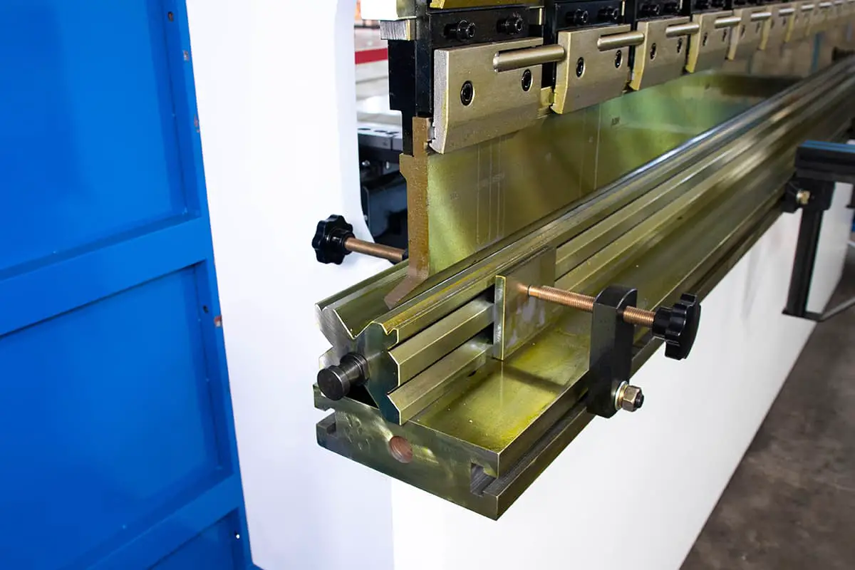
The Z-shaped bending workpiece shown in Figure 1 is a commonly encountered part in production. The size of h is limited by the lower die, with the minimum size that can be bent by the existing lower die shown in Table 1.
Table 1 Minimum size bending
| Plate thickness | 1 | 1.5 | 2 | 2.5 | 3 |
| Minimum size | 7 | 9.5 | 14 | 16 | 18 |
In practical production, if there are numerous Z-shaped bending dies that are smaller than the size mentioned, it would require the design of a composite bending die to accomplish primary molding. This composite die can be used to fold Z-shaped bending dies of various sizes on different sheet materials.
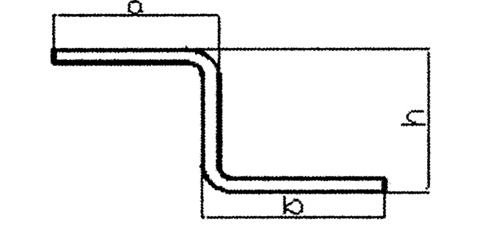
Fig. 1 Z-shaped bending die
2. The process of bending deformation
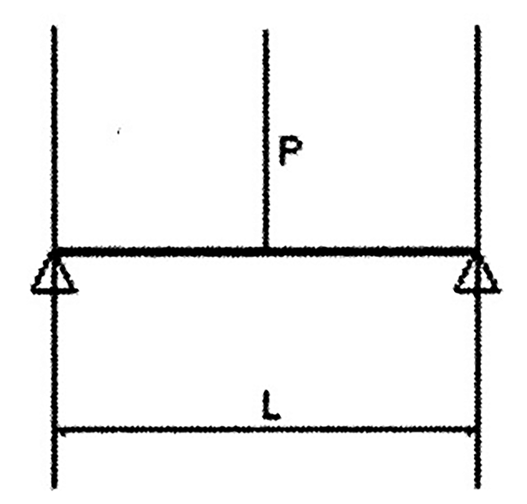
Fig. 2 Action force diagram
As depicted in Figure 2, when a sheet metal is subjected to bending, it experiences bending moment, shear force, and local pressure. However, the primary effect of bending deformation is the bending moment.
The application of external force leads to the corresponding deformation of the sheet metal, which also triggers the appearance of internal force resisting the deformation. The internal force balances with the external force and is measured as stress, which is the internal force per unit area of the object. The higher the external force, the greater the stress and deformation.
When the material’s outer stress is below its elastic limit, the sheet metal is in an elastic deformation state. According to Hooke’s law, the linear relationship between stress and deformation on the section is due to the linear change in distance between the deformation and the central layer (lengthening of the outer layer and shortening of the inner layer).
If the external force is removed, the sheet metal returns to its original shape. However, if the external force continues to increase, the deformation degree of the bending part will continue to escalate until the stress caused by the external force equals the material’s yield limit, leading to plastic deformation of the outer material.
As the external force increases, plastic deformation progresses from the surface to the center. Once the external force is removed, the elastic deformation disappears immediately, but the plastic deformation remains and results in permanent bending deformation.
If the stress caused by the external force exceeds the material’s strength limit, the sheet metal undergoes a fracture from plastic deformation. Inner compression during sheet metal bending also produces plastic deformation, but this type of plastic deformation increases stress on the surface without causing damage, and is therefore often ignored.
3. Calculation method of bending
Now we carefully observe the plastic bending deformation.
Under the action of bending moment, there are three equal lines on the plate section: ab= a1b1 = a2b2.
After bending, the inner layer shortens and the outer layer elongates, that is, ab < a1b1 < a2b2.
Therefore, during bending, the inner material is subjected to compression and becomes shorter, while the outer material is stretched and elongated.
Between tension and compression, there is a layer of material that experiences neither stretching nor compression and is referred to as the neutral layer. This layer remains unchanged in length and does not elongate or shorten.
The process of calculating the bending part involves dividing it into several basic geometric elements, including straight line segments and arc segments. The length of each element is calculated individually, and the total length of all elements is the unfolded length of the bending part.
The Z-shaped bending part in Figure 1 can be divided into five units, as shown in Figure 2. Units 1, 3, and 5 are straight line segments, while units 2 and 4 are arc segments.
As previously discussed, the fiber layer with constant length in the middle before and after bending is referred to as the neutral layer. When calculating the expansion length of the arc segment, it is actually calculating the length of the neutral layer of the arc segment.
The position, x, of the neutral layer from the inner side of the arc (as shown in Figure 3) is usually determined by the r/t ratio.
x = kt
Where:
- t — Material thickness
- k — Neutral layer position coefficient (or neutral layer coefficient)
- k = R – r/t
- R = r + kt
Where:
- R — The distance from the center of radius r to the bending neutral line
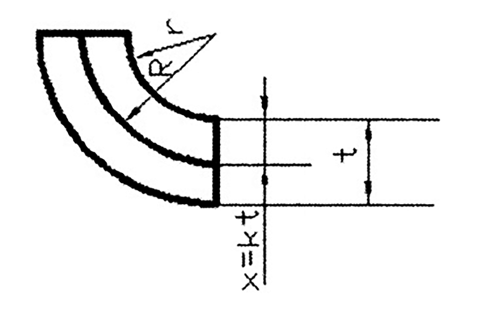
Fig. 3
The value of k varies with the ratio of inner radius to sheet thickness, shown as Table 2:
Table 2
| r/t | 0.25 | 0.5 | 1 | 2 | 3 | 4 |
| k | 0.26 | 0.33 | 0.35 | 0.375 | 0.4 | 0.415 |
In practical production, it is most common to bend steel plates into a 90-degree shape.
The calculation of the arc length for 90-degree bending with different r and t values can be obtained through referencing tables in practical applications.
This article focuses on 90-degree right-angle bending, but it is not efficient to calculate the straight line and arc segments separately for parts with 90-degree sheet metal bending. Instead, they are marked as shown in Figure 1.
When calculating the unfolding material, we can use the marked dimensions directly to simplify the calculation process.
According to figure 1, the developed material length is calculated:
L = a+b+h – 2x
Where:
- x — Common bending coefficient
4. Structure and working process of Z-shaped bending compound die
Table 3 Common bending coefficient x
| Plate thickness t | Inner bending radius r | |||
|---|---|---|---|---|
| 1.0 | 1.5 | 2.0 | 2.5 | |
| 0.5 | 1.0 | 1.2 | 1.4 | 1.6 |
| 1 | 1.9 | 2.1 | 2.3 | 2.5 |
| 1.5 | 2.5 | 2.7 | 2.9 | 3.1 |
| 2.0 | 3.4 | 3.6 | 3.8 | 4.0 |
| 2.5 | 4.0 | 4.2 | 4.4 | 4.6 |
| 3 | 4.9 | 5.1 | 5.3 | 5.4 |
This simple set die is distinct from the conventional die.
It is designed to be simple, quick, easy to process, and straightforward to form. While it may not be as precise as the conventional die, it is still used to quickly and accurately process products.
The forming diagram of the composite die is shown in Table 3.
Processing Principle: The thickness of the gasket is adjusted to achieve the desired width of the V-groove in the upper and lower die, and to perform a one-time Z-fold processing under pressure.
Die Structure: The Z-shaped bending die consists of an upper die, a lower die, a gasket, and an angle prism steel.
Gasket Thickness: The spacer is made of 0.5mm thick steel and is stacked to reach the required thickness.
Prism Steel: A rectangular steel piece within the die, its four angles are chamfered into sides of 0.5mm, 1.0mm, 2.0mm, and 4.0mm, as shown in Table 3.
The special simple die is used to achieve the desired width of the upper and lower die V-groove by adjusting the size of the angular prism steel and the thickness of the gasket, and then performing Z-fold processing in one press.
This method is chosen due to the potential for increasing the V-slot and reducing creasing, so different plate thicknesses require different prongs, as shown in Table 4.
Table 4
| Plate thickness | t<0.8 | 0.8<t<1.0 | 1.0<t<1.2 | 1.2<t1.5 | t>1.5 |
| Prong | 0.5 | 1.0 | 1.0 or 2.0 | 2.0 | 4.0 |
Debugging method of Z-shaped bending die:
1) Both folds of the straight-edge Z-fold are 90°. The distance between the two tool tips is: 1.414/2×h;
2) If the workpiece crease is too deep, then a needs to choose a large angle.
b: pad iron; c: increase angle R;
3) If the height is reached, but the angle is greater than 90°, then a: die eccentricity.
b: Increase the thickness of the shim;
4) If the two sides of the Z-fold are not parallel, it can be achieved by increasing or decreasing the thickness of the shim.
If the upper fold is greater than 90°, the thickness of the lower die shim needs to be increased; and if the lower fold is greater than 90°, the thickness of the upper die shim needs to be increased.
Z-bend expansion calculation method:
When h > normal bending size, it should unfold by two folds.
L=a + b + h – 2x
Where:
- l — Length of unfolded material
When h < the normal bending size, it is expanded by one-step forming.
L = a + B + h – 1.5x
Where:
- x — Common bending coefficient
One of the empirical formulas in practice is to subtract 1.5x from the overall dimension of one molding.