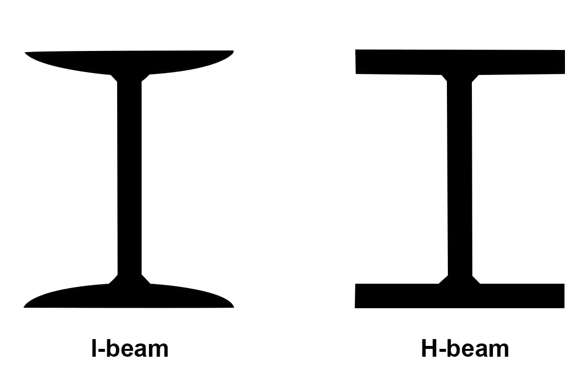
H-beam vs I-beam Steel: 14 Differences Explained
Have you ever wondered about the difference between H-beams and I-beams in construction? While they may look similar, these two types of steel beams have distinct characteristics that make them…
Have you ever struggled with measuring H-beam and I-beam dimensions accurately? This article unravels the mystery behind the correct methods and tools for measuring these essential steel components. From the height of the web to the width of the flange, you’ll learn how to avoid common errors and ensure precision in your measurements. Dive in to discover the best practices and professional tips to perfect your technique and avoid costly mistakes in your projects.
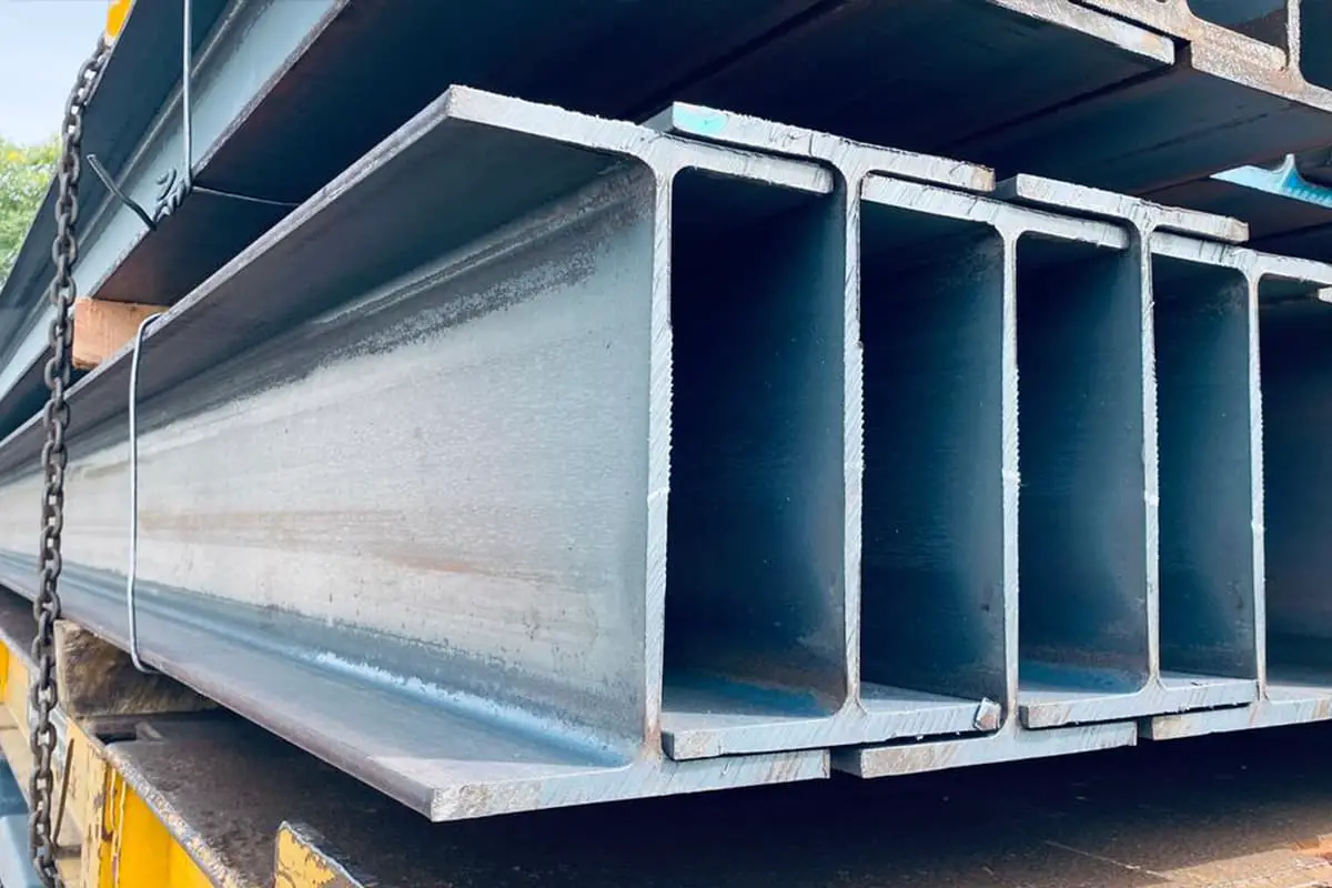
Previously, customers often complained that the H-beam steel they purchased was oversized. When asked to send a photo of their actual measurement, it was found that their methods varied greatly.
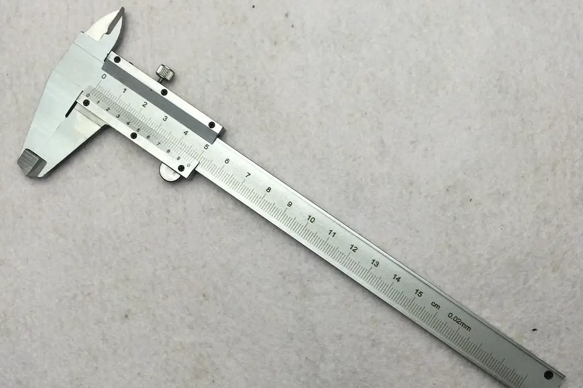
First of all, the measuring tools were not professional. To measure the height of the web and the width of the flange, a vernier caliper should be used, and for thickness, a micrometer or a dedicated thickness gauge is required.

Using a tape measure or a leather tape to measure the height and width is not appropriate, and it is even less suitable for measuring thickness. The thickness tolerance for small H-beam steel is only 0.5mm.
The correct method to measure the dimensions of H-beam steel:
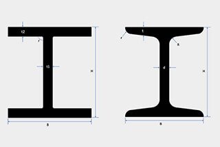
The height of the H-beam’s web should only be measured along the central line of the web, as shown in the diagram below:

Measuring the height of the web is where errors most commonly occur. Since the steel sections are often stacked for storage and the ends have burrs, it’s inconvenient to measure, and some, for the sake of convenience, measure the ends of the flanges from the outside of the stack, but this can lead to data deviation. The following image shows an incorrect method:

The two flanges of an H-beam are not always parallel; sometimes, they can be slightly tilted. Although they may appear parallel to the naked eye, a slight tilt in a 200mm wide flange can result in a height deviation of several millimeters at the ends.
Therefore, it is essential to follow the correct measurement method and ensure that any burrs on the ends are either removed or flattened for accurate measurement.
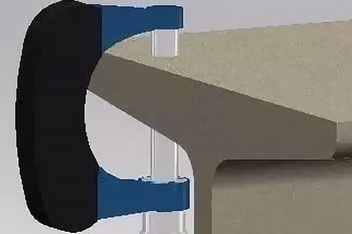
When measuring the width of the flange, the vernier caliper should be placed at an angle to ensure that the contact is not just at a point but over an area, as shown in the diagram below:

Errors in measuring the thickness of the web and flanges are less common. The standard indicates that the thickness of the flange is measured at the B/4 position, and the thickness of the web is at the H/2 position, as shown at the t1 and t2 positions in the diagram below:

However, this does not mean that other areas can exceed the standard requirements. Except near the connection point (inner arc), where the R-corner may cause the thickness to exceed the upper limit of the standard, other areas must not exceed the upper and lower limits of the standard thickness.
Different regulations apply to the ends of the flanges, as specified in the GB/T 11263 standard, which also includes many other measurement methods and requirements for dimensions. Here, we only introduce a few of the most concerning measurement methods.
The measurement of the height of the web, width of the flange, and thickness of the web for I-beam steel is similar to that of H-beam steel. What often confuses us is the measurement of the thickness of the flange. The standard method is to use a micrometer, measuring at the (b-d)/4 position from the end of the flange, at the position marked t, as shown in the diagram below.


From the front view, the enlarged micrometer measurement point is shown in the following diagram, with the thickness indicated by the yellow line representing the thickness of the I-beam steel.

From the side view, the enlarged micrometer measurement point should be a little distance from the end of the I-beam steel to avoid pressing down on burrs and affecting the measurement result.

After seeing the above diagrams, measuring the dimensions of channel steel should also be straightforward. Only the calculation formula for the thickness of the flange is different, which can be understood by referring to the standard.

As the founder of MachineMFG, I have dedicated over a decade of my career to the metalworking industry. My extensive experience has allowed me to become an expert in the fields of sheet metal fabrication, machining, mechanical engineering, and machine tools for metals. I am constantly thinking, reading, and writing about these subjects, constantly striving to stay at the forefront of my field. Let my knowledge and expertise be an asset to your business.