Have you ever wondered how the tiniest measurement can impact the quality of a machine? This article dives into the fascinating world of mechanical measurement, revealing how precision in dimensions, angles, and shapes ensures top-notch product quality and boosts production efficiency. Get ready to explore the crucial role measurement technology plays in modern manufacturing and how it can enhance competitiveness in the industry.
The development of the mechanical industry is reflected in the modernization of measurement technology, the ability to implement the principle of interchangeable production, and other aspects related to geometric characteristics of mechanical parts, tolerance fits, and mechanical measurement.
These directly reflect the product quality and the competitiveness of enterprises.
Mechanical measurement plays a significant role in mechanical manufacturing and is a crucial factor in ensuring product quality and production efficiency. The importance of measurement technology can be reflected in several ways, including:
Control the production process:
Measurement technology provides a control method for mechanical manufacturing, making it more precise and improving the quality of mechanical manufacturing.
Improve product quality:
Measurement technology accurately measures the suitability of product materials and manufacturing technology, thereby improving product quality.
Enhance competitiveness:
Advanced measurement technology can increase production efficiency, reduce costs, and enhance the competitiveness of enterprises.
Realize intelligent manufacturing:
With the continuous development of science and technology, the measurement range has been expanded, from nanometers to several hundred meters can be measured.
Improve process level:
Measurement technology can check whether the processed parts meet the design dimensions, whether the assembly accuracy meets the target value, and ensure the stability and reliability of the production process.
I. Measurement Basic Tasks
Determine measurement units and reference points.
Select measuring instruments and measurement methods.
Analyze measurement errors and measurement accuracy.
In manufacturing, to ensure product quality, ensure the interchangeability of components, analyze part processing technology, and take preventive measures to prevent the production of waste, it is necessary to measure and inspect the dimensions, angles, geometric shapes, relative positions of geometric elements, surface roughness, and other technical conditions of the blanks and components.
Measurement refers to the comparison of the measured entity with the standard unit of measurement, thereby determining the experimental process of the measured entity.
Inspection only needs to determine whether the part is qualified without measuring specific numerical values. Inspection is the general term for measurement and inspection.
Geometric measurement mainly refers to the parameter measurement of surface geometric dimensions and shapes of various mechanical components.
The geometric parameters include the length dimensions, angle parameters, coordinate (position) dimensions, surface geometric shape and position parameters, surface roughness, etc. Geometric measurement is an important measure to ensure the quality of mechanical products and achieve interchangeable production.
Geometric measurement objects are diverse, and different measurement objects have different measured quantities.
For example, the measured quantities of holes and shafts are mainly diameters; the measured quantities of box parts include length, width, height, and hole spacing, etc.; complex parts have complex measured quantities, such as helix errors of screws and rolling cutters.
However, regardless of the shape, the measured parameters can be fundamentally classified into two types: length and angle, and complex quantities can be regarded as combinations of length and angle.
The complete measurement process should include the following four elements:
(1) Measured object
From the perspective of the characteristics of geometric quantities, measurement objects can be divided into length, angle, form error, surface roughness, etc.
From the characteristics of the measured parts, they can be divided into square parts, shaft parts, conical parts, box parts, cams, keys, threads, gears, and various tools.
(2) Measurement unit
The length units include meters (m), millimeters (mm), and micrometers (μm), and the angle units include degrees (°), minutes (′), seconds (″), radians (rad), and microradians (μrad).
(3) Measurement method
Refers to the sum of the methods, measuring tools or instruments, and measurement conditions used to complete the measurement task.
Basic measurement methods include direct measurement and indirect measurement, absolute measurement and relative measurement, contact measurement and non-contact measurement, unilateral measurement and comprehensive measurement, manual measurement and automatic measurement, process measurement and final measurement, active measurement and passive measurement, etc.
The corresponding measurement method should be selected in the most economical way based on the requirements of the measured object.
(4) Measurement accuracy
Measurement accuracy refers to the degree of consistency between the measurement result and the true value of the measured object.
It is not the higher the accuracy, the better, but the most economical way should be selected based on the accuracy requirements of the measured object.
II. Common Knowledge of Measurement
Units of Measurement
China adopts legal units of measurement based on the International System of Units.
1. Units of Length
In the mechanical manufacturing industry, millimeters (mm) and microns (μm) are commonly used units. Millimeters are the most commonly used units of measurement in mechanical measurements.
When using millimeters, only the dimensional figures need to be marked in the mechanical drawings, and the units can be omitted.
The primary units of English measurement for length are feet (ft) and inches (in).
1 ft =12 in
1 in = 25.4 mm
2. Units of Plane Angle
In legal measurement, the basic unit of plane angle is the radian (rad). A radian is the plane angle between two radii of a circle that cut off on the circumference an arc equal in length to the radius.
In mechanical manufacturing, degrees (°) are commonly used as the units of plane angle measurement.
Conversion Table for Commonly Used Measurement Units
Classification of Measurement Methods
Classification based on whether the measured parameter is directly measured or not.
(1) Direct measurement
The measured quantity can be directly read from the reading device of the measuring instrument.
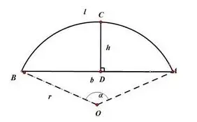
For example, using chord height method to measure the diameter of a circle, measuring shaft diameter or aperture with Vernier caliper or micrometer, and measuring angle with protractor.
(2) Indirect measurement
The measured quantity is indirectly obtained (such as by calculation) based on the measured quantity that has a certain relationship with it.
For example, measuring the diameter of a circle by measuring chord length S and chord height H in order to calculate the circle’s diameter D.
In order to reduce measurement errors, direct measurement is generally used. Indirect measurement can be used when the measured quantity is not easily measured directly.
2. Classification Based on Whether the Displayed Value Represents the Entire Measured Quantity
(1) Absolute measurement
The actual value of the measured quantity can be directly read from the measuring instrument.
When using the absolute measurement method, the measuring range of the measuring instrument must exceed the size of the measured quantity.
Only the deviation of the measured quantity from the standard quantity can be directly obtained. Its measurement range is very narrow.
For example, using a gauge block as a reference, measuring length dimensions on an optical measuring machine.
Generally, the accuracy of relative measurement is higher than that of absolute measurement.
3. Classification Based on Whether the Measuring Head Makes Contact with the Measured Surface During Measurement
(1) Contact measurement
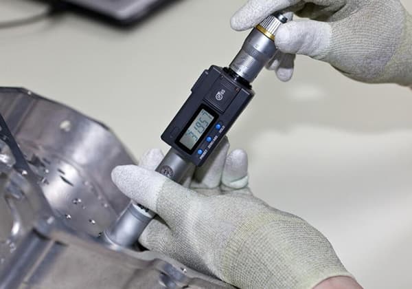
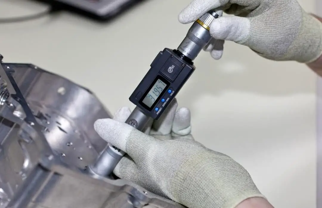
During measurement, the measuring head of the measuring instrument directly contacts the measured surface, and there is a mechanical measuring force, such as measuring dimensions with a micrometer.
(2) Non-contact measurement
During measurement, the measuring head of the measuring instrument does not directly contact the measured surface, but contacts the workpiece through other media (such as light, air, etc.), such as measuring surface roughness with an optical profilometer.
Contact measurement can cause elastic deformation of the relevant parts of the measured surface and the measuring instrument, thereby affecting the measurement accuracy, while non-contact measurement has no such effect.
4. Classification Based on the Number of Parameters Measured in a Single Measurement
(1) Single Item measurement
Each parameter of the measured part is measured separately.
(2) Comprehensive measurement
It measures the comprehensive index reflecting the related parameters of the part.
Comprehensive measurement generally has higher efficiency and is more reliable for ensuring the interchangeability of parts.
It is often used for the inspection of finished parts. Single item measurement can determine the errors of each parameter separately, and is generally used for process analysis, process inspection, and for measuring specified parameters.
III. Error and Tolerance
1. Error
Processing Error
During the production process of machined parts, it is difficult to achieve the ideal state of the dimensional size, shape, micro-geometry (surface roughness), and relative position of parts, due to the influence of various factors such as the limitation of machine tool accuracy, errors in tool grinding angle, and poor rigidity of the process system.
Any machining method cannot produce parts that are absolutely accurate. Even a batch of machined parts may have differences due to various factors.
Even under the same processing conditions, the dimensions of the same batch of workpieces are also different.
In order to meet a certain accuracy requirement, errors must be controlled within a specific range. In order to meet the requirements of interchangeability and make the geometric parameters of parts with the same specifications close to each other, processing errors must also be controlled.
The manifestation of processing errors usually takes several forms:
(1) Dimensional error: The error in the size of the surface of the part itself (such as the diameter error of a cylindrical surface) and the error in the size of the surface between parts (such as the distance between holes).
(2) Shape error: The degree to which the actual surface of the part deviates from the ideal surface in terms of shape, such as the cylindricity error of a cylindrical surface, flatness error of a plane, etc.
(3) Positional error: The degree to which the actual position of a surface, axis, or symmetry plane deviates from the ideal position, such as the parallelism error and perpendicularity error between two surfaces.
(4) Surface quality: The microscopic roughness with small intervals and tiny peaks and valleys left on the surface of a workpiece after processing.
These several types of errors are present simultaneously, among which dimensional error is the most basic. The accuracy of a part refers to the degree of conformity between the actual and ideal values of geometric parameters.
The smaller the difference between the actual and ideal values of geometric parameters, that is, the smaller the error, the higher the machining accuracy.
Therefore, the accuracy of a part is expressed by the size of the error. It can be seen that the concepts of “accuracy” and “error” are only different focal points when evaluating the geometric parameters of a part, but essentially the same.
Measurement Error
The difference between the actual measured value and the true value of the measured geometric quantity is called the measurement error. The measurement error is expressed in absolute error or relative error.
Absolute error: The absolute error δ is the difference between the actual measured value of the measured quantity and the true value, which is:
where X is the actual measured value (measured value), and X0 is the true value or agreed true value.
Relative error:
The relative error is the ratio of the absolute value of the absolute error to the true value of the measured geometric quantity. Since the true value of the measured geometric quantity cannot be obtained, the measured value of the measured geometric quantity is often used instead of the true value for estimation, that is:
There are several factors that contribute to measurement error, including:
1. Error of measuring tools:
The error of measuring tools refers to the error inherent in the measuring tool itself, including errors in the design, manufacture, and use of the measuring tool.
2. Method error:
Method error is the error caused by the imperfect measurement method (including inaccurate calculation formulas, inappropriate measurement method selection, inaccurate workpiece installation and positioning, etc.), which can cause measurement errors.
For example, in contact measurement, the measuring force of the measuring head can cause deformation of the measured part and the measuring device, resulting in measurement errors.
3. Environmental error:
Environmental error refers to the error caused by the environment not meeting the standard measurement conditions during measurement, which can cause measurement errors.
For example, temperature, humidity, air pressure, lighting (causing parallax), vibration, electromagnetic fields, etc. that do not meet standards can all cause measurement errors, among which the influence of temperature is particularly prominent.
For example, when measuring length, the prescribed environment standard temperature is 20℃, but in actual measurement, the temperature of the measured part and the measuring tool will produce deviations from the standard temperature, and the linear expansion coefficient of the material of the measured part and the measuring tool is different, which will produce some measurement errors.
Therefore, the environmental temperature should be reasonably controlled according to the measurement accuracy requirements to reduce the influence of temperature on measurement accuracy.
4. Human error:
Human error refers to the errors caused by human factors, which can result in measurement errors.
For example, incorrect use of measuring instruments, inaccurate measurement alignment, reading or estimation error by the measuring person, etc., can all cause measurement errors.
Classification of Measurement Error:
1. Systematic error:
(1) Constant systematic error:
A constant systematic error is a measurement error whose absolute value and sign remain unchanged when the same quantity is measured multiple times under certain measurement conditions.
For example, the error of the standard block used to adjust the instrument has the same influence on the measurement results of each measurement. This type of error can be eliminated from the measurement results by using a correction method.
(2) Variable systematic error:
The absolute value and sign of the error during the measurement process change according to a certain determinate rule.
For example, the indication error caused by the eccentric installation of the dial of an indicator is a periodic variation following a sine law, and this error in measurement can be eliminated by compensation method.
2. Random error:
Random error is a measurement error that changes randomly, with unpredictable changes in absolute value and sign when measuring the same quantity under certain measurement conditions several times.
Random error is mainly caused by accidental or uncertain factors during the measurement process and is caused by many temporary and uncontrollable factors.
However, when repeated measurements are performed, the errors follow statistical laws.
Therefore, probability theory and statistical principles are often used to handle it.
In practical measurements, to reduce random errors, the same amount can be measured several times, and the arithmetic mean can be taken as the measurement result.
3. Gross error:
Gross error refers to a measurement error that exceeds the expected measurement error under certain measurement conditions, which causes significant distortion in the measurement result. The measured value containing gross errors is called an outlier.
The causes of gross errors can be subjective or objective. Subjective reasons include reading errors caused by the negligence of the measuring person, and objective reasons include measurement errors caused by sudden external vibrations.
Since gross errors significantly distort measurement results, they should be eliminated according to the criteria for identifying gross errors when processing measurement data.
It should be pointed out that the division of systematic errors and random errors is not absolute, and they can be transformed into each other under certain conditions.
In measurement, it is necessary to conduct serious, careful and meticulous observations and remove gross errors from a series of measurement data. In error analysis, systematic errors and random errors are mainly analyzed.
While random errors cannot be corrected or eliminated, their size and patterns can be estimated using probability theory and statistical methods, and efforts should be made to reduce their impact.
Gross errors have a relatively large value and should be avoided as much as possible in measurements.
If gross errors have already occurred, they should be eliminated according to the criteria for identifying gross errors. The commonly used criterion is the “3σ criterion,” also known as the three-sigma rule.
2. Tolerance
To ensure interchangeability of parts, tolerances are used to control errors.
Tolerance should be designed according to standard regulations, and errors that unavoidably occur in machining should be controlled to ensure that finished parts are within the specified tolerance range for interchangeability.
Within the premise of functional requirement satisfaction, the tolerance value should be set as large as possible to obtain the best economic benefit.
Thus, errors arise during the manufacturing process, whereas tolerances are determined by designers. If the error of a part falls within the tolerance range, it is a qualified part. However, if the error exceeds the tolerance range, it is a non-conforming part.
3. Significant Figures and Processing Principles.
The selection of the number of digits in a measured result is a common problem encountered during the measurement process.
The number of significant digits in the measured result should not be too many, which can cause people to mistakenly believe that the measurement accuracy is high.
At the same time, it should not be too few, which can cause a loss of accuracy. Therefore, the number of significant digits of the measurement result should be determined correctly, based on the size of the measurement error.
For example, when measuring the length of an object with a steel ruler with a division value of 1mm, and the length reads 123.4mm, where 123mm is directly read from the steel ruler, and is accurate.
The last digit, 0.4mm, is estimated by the human eye and is unreliable or questionable. The measured data should be expressed in this way, with the last digit being the questionable digit, and the error occurring in this digit.
When the number of significant digits is determined, the principle for determining the last significant digit is as follows:
(1) If the first significant figure after the last significant figure is greater than 5, then add 1 to the last significant figure, and if it is less than 5, disregard it.
(2) When the first digit after the last significant figure is 5, the last significant figure should be adjusted to an even number (add 1 when the last significant figure is odd, and keep it the same when it is even).
For example, if the significant figures are reserved to the third decimal place, the significant figures are as follows:
3.14159 – significant figures 3.142
(3) In addition and subtraction operations, the number of decimal places to be reserved should be the smallest number of decimal places among all numbers, for example:
60.43 + 12.317 + 5.022 – 77.769 ≈ 77.77
(4) In multiplication and division operations, the number of significant figures should be the smallest, for example:
2352 × 0.211 = 496.272 ≈ 496
0.0222 × 34.5 × 2.01= 1.539459 ≈ 1.54.
(5) The number of figures in logarithmic operations should be equal to the number of effective digits in the real number.
(6) In exponentiation operations, the number of significant digits in the exponent should be the same as the number of significant digits in the base.
(7) In square root operations, the number of significant digits should be the same as the number of significant digits in the radicand.
(8) When mathematical constants such as π and 2 are involved in the operation, determine their significant digits according to the above method. To ensure the accuracy of the final operation result, these constants can be appropriately selected by 1-2 digits.
(9) For values representing measurement accuracy, such as measurement limit errors and standard deviations, only one or two significant figures should be taken, and the last digit should be consistent with the last digit of the corresponding measurement result.
For example,
34.0234 ± 0.00021 should be written as 34.0234 ± 0.0002.
IV. Types and Methods of Mechanical Measurement
Length Measurement
Length measurement is a crucial aspect of mechanical measurement systems. There are several methods for measuring length, including:
Vernier Calipers: These devices consist of a main scale and a sliding vernier scale. With accuracy up to 0.02 mm, they are often used for small-scale measurements.
Micrometers: Similar to vernier calipers, micrometers offer higher precision, typically around 0.001 mm. They are used to measure the thickness or diameter of objects.
Coordinate Measuring Machines (CMMs): These are advanced instruments used to make highly precise measurements with accuracies of 0.001 mm or better. They employ a touch probe to determine the three-dimensional coordinates of points on an object’s surface.
Force and Torque Measurement
Force and torque are critical parameters in mechanical systems. Some common methods for measuring them are:
Load Cells: Load cells convert the mechanical force exerted on them into electrical signals. These devices are widely used in weighing scales and load-measuring systems.
Strain Gauges: These are bonded to the surface of a test specimen. As the specimen deforms under stress, the strain gauge changes its electrical resistance, which can be correlated with the applied force.
Torque Wrenches and Transducers: These are used to measure and control the applied torque during assembly or maintenance operations.
Pressure Measurement
Pressure measurement is essential in fluid mechanics applications. Some standard methods for measuring pressure are:
Bourdon Tubes: These are C-shaped or spiral tubes that deform under pressure, causing a pointer to move along a calibrated scale.
Manometers: Manometers measure pressure by comparing the height of a liquid column in the device to a reference level.
Pressure Transducers: These sensors convert pressure into electrical signals and are frequently used in automated systems for monitoring and control.
Temperature Measurement
Temperature is a fundamental parameter in mechanical systems, affecting material properties and performance. Common methods for measuring temperature include:
Thermocouples: These devices consist of two dissimilar metal wires joined at one end, forming a junction. When heated, the junction generates a small voltage proportional to the temperature.
Resistance Temperature Detectors (RTDs): RTDs are based on the principle that the electrical resistance of certain materials increases with temperature, allowing for highly accurate measurements.
Infrared Thermometers: These non-contact devices measure temperature by detecting infrared radiation emitted by an object.
Flow Measurement
Flow measurement is necessary for fluid mechanics applications, e.g., in piping systems or process control. Some techniques for measuring flow are:
Orifice Plates: These are flat plates with a hole placed in the flow, creating a pressure drop proportional to the fluid velocity.
Turbine Flowmeters: These meters use a turbine wheel placed in the flow, rotating at a speed proportional to the flow rate.
Ultrasonic Flowmeters: These devices measure the transit time of ultrasonic waves in the fluid, which varies with flow velocity, allowing for accurate measurements without disrupting the flow.
These methods represent a selection of the common techniques used for mechanical measurement, providing a foundation for understanding the complexities and importance of accurate measurements in modern engineering applications.
Frequently Asked Questions
What are the 3 most common types of measurement in engineering?
Linear measurement: This involves measuring the distance between two points, such as length, breadth, and height. Examples include measuring tapes and vernier calipers.
Angular measurement: This deals with the measurement of angles, as the name suggests. Protractors and universal bevel protractors are common tools used for angular measurement.
Temperature measurement: This is crucial for evaluating the thermal properties of materials and processes in engineering. Thermocouples and thermistors are popular instruments used for temperature measurement.
What are 20 popular mechanical measuring instruments and their uses?
Measuring tape: Used for measuring long distances.
Vernier caliper: Measures small linear dimensions.
Micrometer: Measures the thickness or diameter of tiny objects.
Protractor: Measures angles between two lines.
Dial gauge: Measures variations in height or depth.
Engineer’s square: Checks the straightness and flatness of surfaces.
Bevel gauge: Measures angles other than right angles.
Feeler gauge: Checks clearance between two parts.
Plunger dial indicator: Measures small linear displacements.
Thermocouple: Measures temperature.
Thermistor: Measures temperature.
Anemometer: Measures air velocity.
Hydrometer: Measures density or specific gravity of liquids.
Barometer: Measures atmospheric pressure.
U-tube manometer: Measures pressure difference in fluids.
Level: Determines the horizontal plane.
Clinometer: Measures inclinations or slopes.
Tachometer: Measures rotational speed.
Stroboscope: Measures rotational speed using a flashing light.
Flowmeter: Measures fluid flow rate.
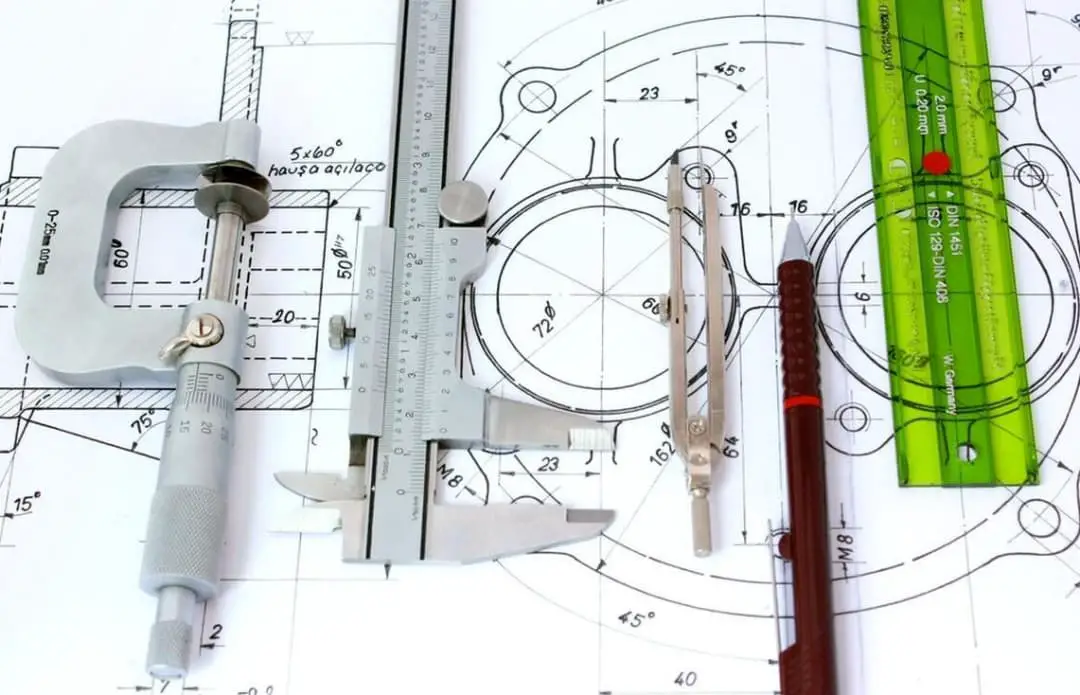
What are some essential tools for engineering measurements?
Several essential tools for engineering measurements include measuring tapes, vernier calipers, micrometers, dial gauges, engineer’s squares, protractors, and thermocouples. These instruments together offer a reliable way to measure various mechanical quantities accurately.
What is the importance of measurement in the field of engineering?
Measurement plays a pivotal role in engineering as it allows engineers to:
Inspect and verify the accuracy of manufactured components.
Ensure that products meet desired specifications.
Maintain consistency in manufacturing and assembly processes.
Evaluate the efficiency and performance of machines.
Conduct research and improve existing designs.
What are the standard units for measuring mechanical quantities?
The International System of Units (SI) is the most widely used system for measuring mechanical quantities. Some standard units include:
Meter (m) for length.
Kilogram (kg) for mass.
Second (s) for time.
Kelvin (K) for temperature.
Newton (N) for force.
Joule (J) for energy.
Which measurement types are commonly used in mechanical engineering?
In mechanical engineering, various measurement types are commonly used, such as linear, angular, and temperature measurements. Other crucial measurement types include force, pressure, fluid flow, and vibration. These measurements are essential for designing, manufacturing, and maintaining mechanical systems and components.
As the founder of MachineMFG, I have dedicated over a decade of my career to the metalworking industry. My extensive experience has allowed me to become an expert in the fields of sheet metal fabrication, machining, mechanical engineering, and machine tools for metals. I am constantly thinking, reading, and writing about these subjects, constantly striving to stay at the forefront of my field. Let my knowledge and expertise be an asset to your business.
Attention all mechanical engineers and manufacturing professionals! Are you struggling with pesky anodizing defects in your aluminum products? Look no further! In this blog post, we'll dive deep into the…
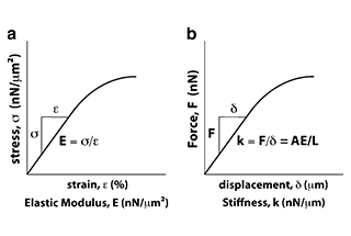
Ever wondered why some materials bend easily while others remain rigid? This blog dives into the fascinating world of elastic modulus and stiffness, unraveling their crucial roles in engineering. By…
Have you ever wondered what makes a perfect circle? In the world of mechanical engineering, roundness is a crucial concept that affects the performance and longevity of rotating components. This…
In today's fast-paced manufacturing world, efficient deburring is crucial. With numerous methods available, choosing the right one can be daunting. In this blog post, we'll explore various deburring techniques, from…
Have you ever wondered what keeps the world spinning smoothly? The unsung heroes behind the scenes are bearings. These small but mighty components play a crucial role in reducing friction…
Gears are the unsung heroes of the mechanical world, quietly working behind the scenes to keep machines running smoothly. But have you ever wondered what materials these critical components are…
This article explores the top 5 cooling tower manufacturers shaping our world. Learn how these companies innovate to keep industries running smoothly and efficiently. Get ready to uncover the secrets…
Have you ever wondered what keeps our gas systems running smoothly and safely? In this article, we explore top gas regulator manufacturers, uncovering their innovations and contributions to the industry.…
Ever wondered why connecting copper and aluminum wires is problematic? This article explains the risks associated with connecting these two metals due to their differing electrochemical properties, which can lead…