Calculate Steel Weight for 30 Metals: Formula & Calculator
Have you ever wondered how to accurately calculate the weight of steel or metal for your projects? In this blog post, we'll explore the fascinating world of steel weight calculation…
Ever wondered how to determine the perfect steel beam for your project? This article will guide you through the essentials of calculating the load-bearing capacity of H-beams and I-beams. By the end, you’ll know how to choose the right beam and ensure your structure’s safety and efficiency.
I believe you still want to know the weight capacity of a steel beam and how to calculate it?
See also:
Alternatively, you may be interested in determining the proper size of an H-beam for your construction project.
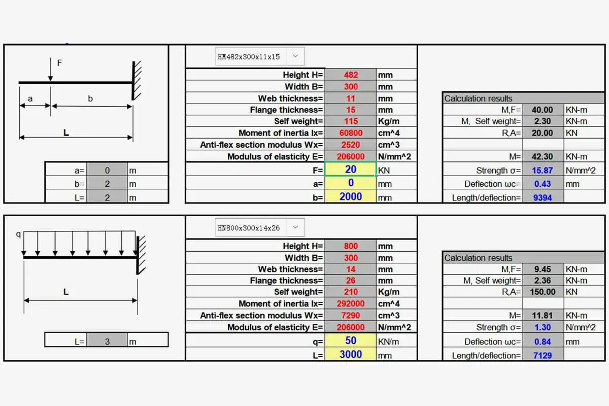
To assist you, we have supplied you with a robust beam load capacity calculator and a load capacity chart, as shown in the screenshot below.
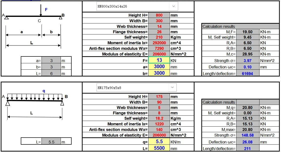
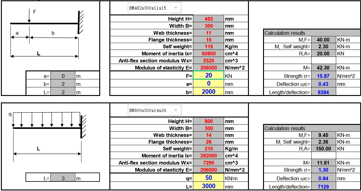
And it’s in an Excel format, which can automatically perform the calculation once you have entered the necessary information.
You can download the tool by clicking the link below. Don’t forget to enable the macro function in Excel to ensure proper functioning.
The bending bearing capacity formula is:
Mu=b’*h’*f*(0.5*h-0.5*h’)+(0.5*h-h’)*b*f*0.5*(0.5*h-h’)
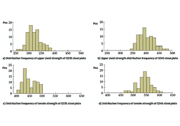
F – design value of yield strength
b – web thickness
b ‘- flange width
h – high
h ‘- flange thickness
As for the bearing capacity of tension and compression, I think it is not necessary for me to explain here. As for eccentric tension and compression, it is not very difficult to calculate by yourself.
For example:
How much can I-beam #25 bear when the span is 4m and the load is evenly distributed?
Calculation:
For #25 I-beam, W = 401.4cm3, [σ]=210N/mm2, overall stability coefficient φb=0.93
Bending moment formula M = QL2/8
Strength formula σ = M/W
According to the formula: q=8σW/L2=8*210*401400/4*4=42.1kN/m
Overall stability requirement: 42.1 * 0.93 = 39.2kn/m
Partial factor requirement (safety factor): 39.2 / 1.4 = 28kN/m
Safe use: 28kN/m
The above calculation does not consider the self-weight and deflection checking calculation of I-beam.
H-shaped steel is better suited for load-bearing.
Whether it is ordinary or light I-beam steel, due to its relatively high and narrow cross-sectional dimensions, the inertia moments of the two main axes in the cross-section differ greatly.
As a result, it can only be directly used for members subjected to bending in the plane of their webs, or it can be formed into lattice stress-bearing members.
It is not suitable for members subjected to axial compression or bending perpendicular to the plane of the web, limiting its scope of application.
On the other hand, H-section steel is an efficient and economical profile, thanks to its reasonable section shape, which enhances its effectiveness and improves its cutting capacity.
Unlike ordinary I-beams, the flange of H-beams is wider, and their inner and outer surfaces are typically parallel, making it easier to connect with other members using high-strength bolts.
Its size forms a reasonable series, and its models are comprehensive, making it convenient for design and selection purposes.
Features of H-beam steel
The inner and outer sides of the flange of H-shaped steel are parallel or nearly parallel, and the end of the flange is at a right angle, making it known as the parallel flange I-beam.
The web thickness of H-shaped steel is smaller than that of an ordinary I-beam with the same height as the web, and the flange width is larger than that of an ordinary I-beam with the same height as the web, hence also referred to as the wide flange I-beam.
The shape of the H-beam results in improved section modulus, moment of inertia, and corresponding strength compared to an ordinary I-beam of the same weight.
When used in different metal structures, the H-beam exhibits superior performance in terms of bending moment, pressure load, and eccentric load, resulting in improved bearing capacity and the possibility of saving 10% to 40% of metal compared to an ordinary I-beam.

As the founder of MachineMFG, I have dedicated over a decade of my career to the metalworking industry. My extensive experience has allowed me to become an expert in the fields of sheet metal fabrication, machining, mechanical engineering, and machine tools for metals. I am constantly thinking, reading, and writing about these subjects, constantly striving to stay at the forefront of my field. Let my knowledge and expertise be an asset to your business.