Before selecting a PLC, it is important to determine the system scheme. Once the system scheme has been determined, you can choose the manufacturer and model that best suits your needs.
This article provides detailed information on manufacturers, models, input/output (I/O) point count, control functions, and more, to help you select the most suitable PLC for your needs.
1. Manufacturers of PLCs
When selecting a manufacturer for your PLC, it is important to consider factors such as equipment user requirements, designer familiarity with different manufacturers’ PLCs and design habits, consistency of compatible products, and technical services.
From the perspective of the reliability of the PLC itself, in principle, there should be no problems with the reliability of products from major overseas companies. Generally speaking, for controlling independent equipment or simpler control systems, Japanese PLC products have certain cost advantages.
For larger-scale distributed control systems with high requirements for network communication and openness, European and American PLCs have advantages in network communication functionality.
In addition, for some special industries (such as metallurgy and tobacco), PLC systems with mature and reliable operational performance in the relevant industry field should be selected.
2. Input/output (I/O) point count
The I/O point count of a PLC is one of its basic parameters. The determination of I/O point count should be based on the total number of I/O points required for the control equipment.
In general, PLCs should have appropriate margins for I/O points. Typically, after adding 10% to 20% of expandable margins based on the calculated input/output point statistics, this data can then be used as an estimated input/output point count.
When placing actual orders, the input/output point count needs to be adjusted based on the specific characteristics of the manufacturer’s PLC product.
3. Storage Capacity
The storage capacity refers to the size of the hardware storage unit that the programmable logic controller can provide, while the program capacity refers to the size of the storage unit used by the user application project in the memory.
Therefore, the program capacity is smaller than the storage capacity. During the design phase, since the user application program has not yet been compiled, the program capacity is unknown and can only be determined after program debugging.
In order to estimate program capacity during the design selection process, the estimated storage capacity is usually used as a substitute. There is no fixed formula for estimating the PLC’s memory capacity, and many literature sources provide different formulas.
Generally, the total number of words in memory is estimated to be 10-15 times the digital I/O point count plus 100 times the analog I/O point count (each word is 16 bits), and an additional 25% margin should also be considered.
4. Control Function
This selection includes the choice of operational, control, communication, programming, diagnostic features, and processing speed.
1. Operational Function
The operational functions of a simple PLC include logical operations, timing, and counting functions. The operational functions of a regular PLC also include data shift, comparison, and other operational functions.
More complex operational functions include algebraic operations, data transfer, etc. Large PLCs also have advanced operational functions such as PID operation for analog signals.
With the emergence of open systems, most PLCs now have communication functions, some products have communication with lower-level machines, some have communication with peer or upper computers, and some even have data communication functions with factories or enterprise networks.
When selecting PLC based on actual requirements, it is important to select the necessary operational functions reasonably.
In most application scenarios, only logical operations and timing/counting functions are needed.
Some applications require data transfer and comparison, and algebraic operations, numerical conversion, and PID operations are only used for analog signal detection and control. Some applications also require decoding and encoding operations to display data.
2. Control Function
Control functions include PID control operations, feed-forward compensation control operations, ratio control operations, etc., which should be determined based on the control requirements. Since PLC is mainly used for sequential logic control, single-loop or multi-loop controllers are often used to solve analog control in most scenarios.
Sometimes dedicated intelligent input/output units are used to complete the required control functions, improving PLC processing speed and saving storage capacity. For example, using PID control units, high-speed counters, analog units with speed compensation, ASCII conversion units, etc.
3. Communication Function
Medium to large-scale PLC systems should support multiple field buses and standard communication protocols (such as TCP/IP), and should be able to connect with factory management networks (TCP/IP) when necessary.
The communication protocol should comply with ISO/IEEE communication standards and should be an open communication network.
The communication interface of the PLC system should include serial and parallel communication interfaces (RS2232C/422A/423/485), RIO communication ports, industrial Ethernet, commonly used DCS interfaces, etc.
The communication bus of medium to large-scale PLCs (including interface devices and cables) should consider redundant configuration, and the communication bus should comply with international standards. The communication distance should meet the actual requirements of the device.
In the communication network of the PLC system, the communication rate of the upper-level network should be greater than 1Mbps, and the communication load should not exceed 60%.
The communication network of the PLC system has several forms:
- PC is the main station, and multiple PLCs of the same model are the sub-stations, forming a simple PLC network;
- One PLC is the main station, and other PLCs of the same model are subs-stations, forming a master-slave PLC network;
- The PLC network is connected to a large-scale DCS through a specific network interface as a subnet of the DCS;
- A dedicated PLC network (dedicated PLC communication network of various manufacturers).
To reduce the CPU’s communication task, different communication processors with different communication functions (such as point-to-point, fieldbus, industrial Ethernet) should be selected based on the actual needs of the network composition.
4. Programming Function
Offline programming:
PLC and the programmer share a CPU. In programming mode, the CPU only serves the programmer and does not control the field device. After programming is completed, the programmer switches to the run mode, and the CPU controls the field device but cannot perform programming.
Offline programming reduces system costs but is inconvenient to use and debug.
Online programming:
The CPU and the programmer have their own CPUs. The main CPU is responsible for field control and exchanges data with the programmer in one scanning cycle. The programmer sends the online programmed program or data to the host, and the host runs according to the new received program in the next scanning cycle.
This method has a higher cost, but the system debugging and operation are convenient and are commonly used in medium to large-scale PLCs.
Five standardized programming languages:
Sequential Function Chart (SFC), Ladder Diagram (LD), Function Block Diagram (FBD) three graphical languages, and Instruction List (IL) and Structured Text (ST) two text languages.
The selected programming language should comply with its standard (IEC6113123) and support multiple language programming forms, such as C, Basic, Pascal, etc., to meet the control requirements of special control scenarios.
5. Diagnostic Function
The diagnostic function of the PLC includes hardware and software diagnostics. Hardware diagnostics determine the location of hardware faults through hardware logic judgments, while software diagnostics include internal and external diagnostics.
Diagnosing the performance and functions of the PLC internally through software is internal diagnosis, while diagnosing the CPU and the information exchange function of external input/output components through software is external diagnosis.
The strength of the diagnostic function of the PLC directly affects the technical capabilities required of operators and maintenance personnel and affects the average repair time.
6. Processing Speed
PLC works in a scanning mode. From the perspective of real-time requirements, the processing speed should be as fast as possible. If the signal duration is shorter than the scanning time, the PLC will not be able to scan the signal, resulting in the loss of signal data.
The processing speed is related to the length of the user program, CPU processing speed, software quality, etc.
Currently, the response time and speed of PLC contacts are fast, and the execution time of each binary instruction is about 0.2~0.4μs, which can meet the requirements of high control and fast response applications.
The scan cycle (processor scan cycle) should meet the following criteria: the scanning time of small PLC should not exceed 0.5ms/K, and the scanning time of medium to large-scale PLC should not exceed 0.2ms/K.
7. PLC Models
PLCs can be classified into two types: integral and modular, based on their structures.
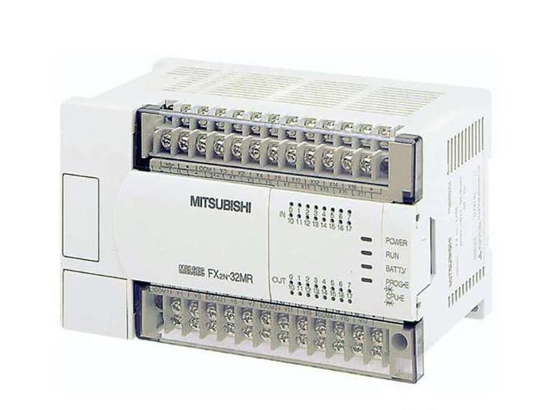
Integral PLCs have a relatively fixed and small number of I/O points, which limits users’ choices and is typically used in small control systems. Examples of this type include the Siemens S7-200 series, Mitsubishi FX series, and Omron CPM1A series.
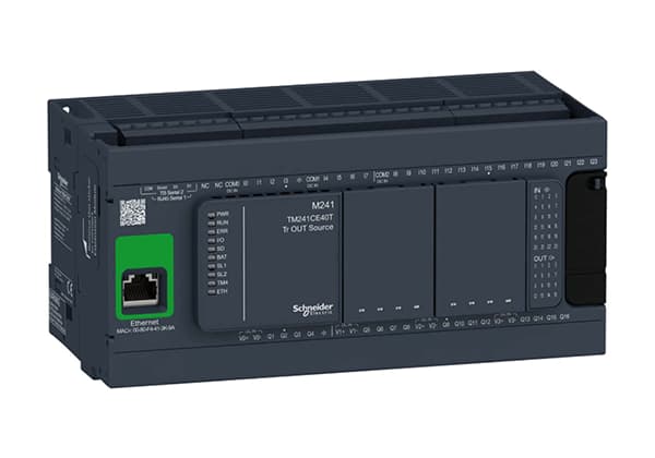
Modular PLCs provide multiple I/O modules that can be plugged into the PLC baseboard, allowing users to select and configure the number of I/O points according to their needs.
This makes modular PLC configurations more flexible and is commonly used in medium to large control systems. Examples of this type include the Siemens S7-300 and S7-400 series, Mitsubishi Q series, and Omron CVM1 series.
8. Selection of Various Modules
1. Digital I/O Module
The selection of digital input/output modules should consider application requirements. For example, for input modules, considerations should include input signal levels, transmission distances, etc.
There are also many types of output modules, such as relay contact output, AC120V/23V bidirectional thyristor output, DC24V transistor drive type, DC48V transistor drive type, etc.
Usually, relay output modules have the advantages of low cost and wide voltage range. However, they have a shorter service life, longer response time, and require surge absorption circuits when used with inductive loads.
Bidirectional thyristor output modules have a faster response time and are suitable for frequent switching and low power factor load occasions but are more expensive and have poorer overload capacity.
In addition, input/output modules can be divided into specifications such as 8-point, 16-point, 32-point, etc., according to the number of inputs/outputs, and should be reasonably equipped according to actual needs.
2. Analog I/O Module
Analog input modules can be divided into current input type, voltage input type, thermocouple input type, etc., according to the type of analog input signals.
The signal level of a current input module is usually 4~20mA or 0~20mA, while that of a voltage input module is usually 0~10V, -5V~+5V, etc. Some analog input modules can be compatible with both voltage and current input signals.
Analog output modules also have voltage output type and current output type. The signal range of current output is usually 0~20mA, 4~20mA, while that of voltage output signals is usually 0~0V, -10V~+10V, etc.
Analog input/output modules can be divided into specifications such as 2-channel, 4-channel, 8-channel, etc., according to their input/output channel numbers.
3. Function Modules
Function modules include communication modules, positioning modules, pulse output modules, high-speed counting modules, PID control modules, temperature control modules, etc.
When choosing a PLC, the possibility of matching function modules should be considered, which involves both hardware and software aspects.
8. General Rules
After the PLC model and specifications are roughly determined, the basic specifications and parameters of each component of the PLC can be determined one by one according to the control requirements, and the models of each component module can be selected.
When selecting module models, the following principles should be followed:
1. Economy
When selecting a PLC, the performance-price ratio should be considered. When considering economy, factors such as application scalability, operability, input-output ratio, etc. should be compared and balanced to choose a satisfactory product.
The number of input/output points has a direct impact on the price. Increasing the number of input/output cards requires additional costs. When the number of points increases to a certain value, the corresponding memory capacity, rack, motherboard, etc. must also be increased.
Therefore, increasing the number of points has an impact on the selection of CPU, memory capacity, and control function scope. It should be fully considered in estimation and selection to make the entire control system have a more reasonable performance-price ratio.
2. Convenience
Generally, there are many types of modules that can meet the control requirements as a PLC. When selecting, the principle of simplifying circuit design, convenience of use, and minimizing external control components should be followed.
For example, for input modules, the input form that can be directly connected with external detection elements should be prioritized to avoid using interface circuits.
For output modules, output modules that can directly drive loads should be prioritized, and intermediate relays and other components should be minimized.
3. Generality
When selecting, the uniformity and generality of each component module of the PLC should be considered to avoid too many types of modules.
This is not only conducive to procurement, reducing spare parts, but also can increase the interchangeability of various components of the system, providing convenience for design, commissioning, and maintenance.
4. Compatibility
When selecting each component module of the PLC system, compatibility should be fully considered to avoid poor compatibility issues.
The production manufacturers of the main components of the PLC system should not be too many. If possible, products from the same manufacturer should be selected.