6 Simple Steps to Choosing the Perfect Sensors for Your Project
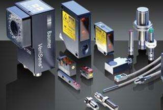
Ever struggled to choose the right sensor for your project? With so many options available, selecting the perfect one can be daunting. This article breaks down six simple steps to…
Have you ever wondered how to choose the right industrial camera for your visual system? Selecting the perfect camera involves understanding the different types, such as array and line scan cameras, and considering factors like resolution, sensor size, and interface types. This article breaks down these critical aspects, helping you make an informed decision to meet your specific needs in various industrial environments. By the end of the article, you’ll be equipped with the knowledge to enhance your visual inspection systems efficiently.
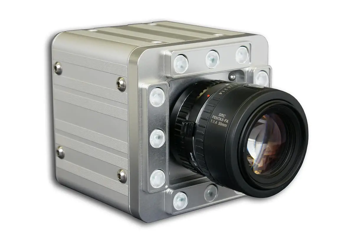
Industrial cameras differ from the cameras in our smartphones or DSLR cameras. They can operate in harsh environments, such as high temperatures, high pressures, and dusty conditions. Industrial cameras mainly consist of array cameras and line scan cameras.
Line scan cameras are primarily used in scenarios that require high precision and fast movement, while array cameras have a wider range of applications.
These cameras have a linear configuration and are typically used in two scenarios. First, they are utilized for inspecting elongated, belt-like fields of view, often on rotating drums. Second, they are chosen for applications requiring a large field of view with high precision. The two-dimensional images we see from line scan cameras are formed by multiple line scans.
Advantages of line scan cameras include the ability to have a high number of one-dimensional pixels, fewer total pixels compared to array cameras, flexible pixel sizes, and high frame rates. This makes them particularly suitable for measuring one-dimensional dynamic targets.
Array cameras are more widely used in machine vision applications. The advantage of array CCD cameras is their ability to directly capture two-dimensional image information, providing intuitive measurement images.
They can be used for short exposure times, which is beneficial for capturing dynamic scenes, and are also suitable for static objects. Since I mainly use array cameras, this section will focus on selecting array cameras.
For static subjects, CMOS cameras are a cost-effective option. However, for moving targets, CCD cameras are preferable. If high-speed acquisition is required — referring to collection speed, not motion speed — CMOS cameras, with their superior collection rates, should be considered. For high-quality imaging, such as size measurement, CCDs are recommended, as they generally outperform CMOS in small sensors.
CCD industrial cameras are mainly used for capturing images of moving objects and are widely employed in automated visual inspection solutions. With the advancement of CMOS technology, CMOS industrial cameras are increasingly popular due to their low cost and power consumption.
The front of an industrial camera is for attaching lenses, and they typically have standardized professional interfaces. On the back, there are usually two interfaces: a power interface and a data interface.
Industrial camera interfaces include USB 2.0/3.0, CameraLink, Gige, 1394a/1394b, CoaXPress, and others. Here, only a few common types are introduced.
USB Interface:
Supports hot-plugging, ease of use, standardized and unified, connects multiple devices, and can be powered via USB cable.
However, it lacks a standardized protocol and has a master-slave structure, with high CPU usage and unguaranteed bandwidth. USB 3.0 interfaces can self-power, but an external power source can be used if USB power is unstable.
Gige Gigabit Ethernet Interface:
Developed based on the Gigabit Ethernet communication protocol, it is suitable for industrial imaging applications, transmitting uncompressed video signals over a network.
It offers good expandability, with data transmission lengths up to 100m (extendable indefinitely with repeaters), a bandwidth of 1Gbit for instant data transmission, uses standard NIC cards (or those pre-installed on PCs), economical, and utilizes cheap cables (standard Ethernet cables CAT-6) with standard connectors. It is easy to integrate, cost-effective, and widely applicable.
CameraLink Interface:
A serial communication protocol using LVDS interface standards, known for high speed, strong anti-interference capabilities, and low power consumption. Developed from Channel link technology, it adds some transmission control signals and defines related standards. The protocol uses MDR-26 pin connectors, offers high speed with bandwidth up to 6400Mbps, strong anti-interference capabilities, and low power consumption.
Gige interfaces simplify setting up multiple cameras, supporting 100-meter cable output. The Camera Link interface is specifically designed for high-speed image data needs. USB 3.0 interfaces are known for their simplicity and real-time capabilities.
Currently, the most widely used interface in machine vision is the Gige (Ethernet) interface, which offers significant advantages over other interfaces in terms of transmission speed, distance, and cost.
Resolution is a key factor in camera selection. It’s important to understand the relationship between resolution, pixels, accuracy, pixel size, and sensor size, as these terms are often confused.
Camera resolution refers to the number of pixels captured in each image, indicating the total number of light-sensitive chips, typically measured in millions and arranged in a matrix.
For example, a million-pixel camera might have a pixel matrix of WxH = 1000×1000. Pixel size varies across different devices, with each pixel having a specific position and assigned color value. The arrangement and color of these pixels determine the appearance of the image.
Sensor (CCD/CMOS) sizes can be confusing, as terms like 1/1.8 inch or 2/3 inch do not refer to any particular dimension or diagonal size of the sensor, making it hard to conceptualize their actual size.
| Sensor type | Diagonal line (mm) | Width (mm) | Height (mm) |
| 1/3” | 6.000 | 4.800 | 3.600 |
| 1/2.5 | 7.182 | 5.760 | 4.290 |
| 1/2” | 8.000 | 6.400 | 4.800 |
| 1.8” | 8.933 | 7.176 | 5.319 |
| 2/3” | 11.000 | 8.800 | 6.600 |
| 1″ | 16.000 | 12.800 | 9.600 |
| 4/3” | 22.500 | 18.800 | 18.500 |

The sensor size affects the field of view and working distance. With larger sensor sizes at the same pixel density, pixel size increases, enhancing each pixel’s light-sensitive area and improving image quality. Under the same working distance and lens, a larger sensor can capture a broader field of view.
With camera resolution and sensor size, pixel size can be calculated:
Pixel Size = Sensor Size / Resolution (number of pixels)
This yields the pixel size in both width and height.
Pixel size refers to the actual physical size of each pixel on the chip’s pixel array, such as 3.75um x 3.75um. To some extent, pixel size reflects the chip’s responsiveness to light. Larger pixels can receive more photons, producing more electric charge under the same lighting conditions and exposure time.
This is particularly relevant for low-light imaging, where pixel size is an indicator of the chip’s sensitivity. It’s crucial to distinguish this from camera resolution: smaller resolution values indicate higher resolution, whereas larger pixel sizes imply higher sensitivity. These are two distinct concepts.
Accuracy refers to the size of the actual object represented by a single pixel, expressed in (um*um)/pixel. It’s important to note that pixel size is not the same as accuracy.
Pixel size is a fixed characteristic of the camera’s mechanical construction, whereas accuracy relates to the camera’s field of view and is variable. The smaller the accuracy value, the higher the accuracy.
The size represented by a single pixel = Field of view width / Width resolution = Field of view height / Height resolution
Additional Note: Considering the distortion at the camera’s edge of view and the stability requirements of the system, we generally do not equate a single pixel unit with one measurement accuracy value.
Sometimes, depending on the light source, the calculation value is increased. With a backlight, the accuracy is 1~3 pixels, while with a direct light source, it is 3~5 pixels. For example, using a 500W pixel camera with a resolution of 25002000 and a field of view of 100mm80mm:
It’s important to understand that when calculating the resolution based on known accuracy, a camera with a higher resolution than the calculated value is often necessary to meet the requirements.
Image resolution is relatively straightforward to understand. It refers to the number of pixels used to display an image per unit distance, similar in concept to accuracy but expressed differently.
When the field of view, i.e., the target size, is fixed (the target size is generally considered as the field of view when selecting a camera), the greater the camera resolution, the higher the accuracy and image resolution.
When the field of view is not fixed, cameras with different resolutions can achieve the same accuracy. In such cases, choosing a camera with larger pixels can expand the field of view, reduce the number of shots needed, and increase testing speed.
For instance, if one camera has 1 million pixels and another has 3 million pixels, and both have the same clarity (20um/pixel in accuracy), the first camera’s FOV is 20mm×20mm = 400 square mm, while the second camera’s FOV is 1200 square mm. If capturing the same number of targets on a production line, the first camera might need to take 30 images, whereas the second camera would only need to take 10.

As the founder of MachineMFG, I have dedicated over a decade of my career to the metalworking industry. My extensive experience has allowed me to become an expert in the fields of sheet metal fabrication, machining, mechanical engineering, and machine tools for metals. I am constantly thinking, reading, and writing about these subjects, constantly striving to stay at the forefront of my field. Let my knowledge and expertise be an asset to your business.