Achieving Smooth Elevator Parts: Sharp Edge & Burr Control
Ever wondered why tiny metal burrs can cause big problems? This article explores the causes and dangers of sharp edges and burrs on sheet metal parts, especially in elevators. From…
How can a seemingly simple process like shot peening dramatically enhance material surfaces? By propelling small projectiles onto a surface, shot peening induces beneficial residual stress, enhancing strength, fatigue resistance, and durability in various industries like aerospace and automotive. This article explores the mechanisms, material impacts, and testing methods involved in shot peening, offering insights into its transformative effects on material properties. Dive in to discover how this technique can significantly improve the performance and lifespan of critical components.
Shot peening is a surface strengthening process that is relatively simple compared to other surface modification methods, but its effects are significant. It is used in various industries, including aerospace, locomotives, automobiles, and others.
The principle behind shot peening involves using projectiles to impact the material, creating small pits on the surface and causing plastic deformation. This results in residual stress on the metal surface. The compressed crystal grains under the surface must be restored to their original shape, which creates a uniform residual compressive stress layer that strengthens the material’s surface.
As a result of shot peening, the surface layer of the material undergoes structural changes. The grains become finer, the dislocation density and lattice distortion increase, and a high residual compressive stress is formed. This residual stress significantly improves the material’s fatigue resistance and fatigue life, as well as its strength, hardness, resistance to stress corrosion, and high-temperature oxidation properties.
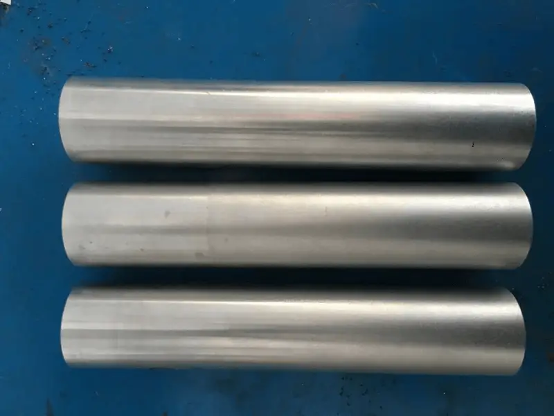
The test utilized barrel-shaped parts made of 2A14 aluminum alloy, a material known for its high strength, good heat resistance, good machinability, and good electric welding and welding seam performance. The specific composition of this material is shown in Table 1.
Table 1 2A14 aluminum alloy chemical composition
| Element | Si | Cu | Mg | Zn | Mn | Ti | Ni | Al |
|---|---|---|---|---|---|---|---|---|
| Ingredient | 0.6-1.2 | 3.9-4.8 | 0.4-0.8 | ≤0.3 | 0.4-1.0 | ≤0.15 | ≤0.1 | others |
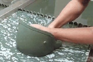
The 2A14 aluminum alloy barrel-shaped parts were divided into four groups (see in Figure 1),
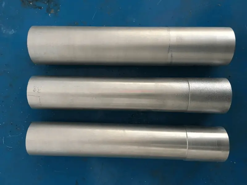
(a) The 1st group
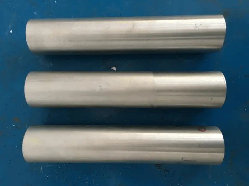
(b) The 2nd group
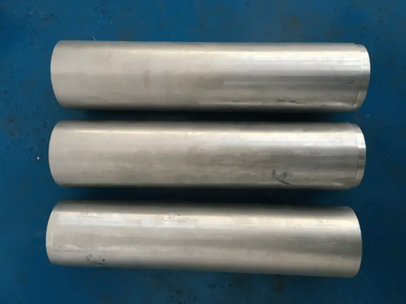
(c) The 3rd group
(d)The 4th group
Fig.1 Parts before shot peening
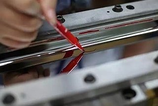
The test was conducted using an SP1200 G4 pneumatic shot blasting machine, and its working principle is depicted in Figure 2. The glass fiber reinforced plastic shot was absorbed into the high-pressure nozzle under negative pressure, and then the shot was propelled onto the surface of the part under high pressure.
The shot blasting pellets used in the test were made of glass pellets with the specification of AGB70 and met the AMS 2431/6 standard. Their appearance is shown in Figure 3.

Fig.2 Shot peening treatment

Fig.3 Glass pellets
The strength of the shot peening was verified using a self-made tooling, which is depicted in Figure 4. The standard base for verifying the ALMEN test piece was securely fastened to the self-made tooling with screws, and the ALMEN standard test piece was fixed on the standard base.
The ALMEN standard test piece was compliant with the requirements of both the SAE J 442 and AMS 2431/2 documents. A minimum of four tests were conducted to meet the requirement.

Fig.4 Homemade work fixture
During the shot peening process, the projectiles are propelled onto the surface of the material with a certain kinetic energy, forming a regular flow under a specific air pressure. The speed and impact force of the projectiles are determined by the air pressure, while the degree of plastic deformation of the material is determined by the strength of the shot peening.
The saturation curve is drawn and the saturation point is determined through the verification of the ALMEN test piece, allowing for the determination of the corresponding shot peening strength. When determining the airflow pressure, it is advisable to use a lower pressure to reduce wear on the material’s surface.
The projectile flow rate, which is the number of projectiles ejected per unit time, is related to the airflow pressure. A low airflow pressure should correspond to a lower flow rate. In this case, an airflow pressure of 0.5×10⁵Pa was selected, resulting in a projectile flow rate of 3kg/min.
By adjusting the up and down movement speed of the spray gun, different shot peening strengths can be achieved. With the spray gun’s movement speed adjusted to 300mm/min, 600mm/min, and 900mm/min, parts were obtained with shot peening strengths of 0.35mm (A), 0.31mm (A), and 0.27mm (A), respectively.
The shot peening time is determined by the saturation time of the ALMEN test piece. However, the time needed to achieve 100% coverage on the surface of the part can be used as a reference based on the saturation time of the test piece.
The Avrami equation, which is based on random statistics for average coverage, assumes that the arrival speed of the particles is consistent. The equation is as follows:
In the formula,
According to the Avrami equation, the coverage rate approaches 100% but it is theoretically impossible to reach 100%. The time required to attain the final 10% coverage is 1.5 times greater than the time required for the initial 90% coverage. The shot peening time required to reach the last 1% coverage will account for approximately 20% of the total time, and the time required for the last 2% coverage will be nearly 40% of the total time. In the case of 99% coverage, 85% of the positions were hit at least twice and 50% were hit five or more times.
Typically, if the coverage rate reaches 98%, it is considered equal to 100% coverage. However, achieving 100% coverage may result in excessive shot peening. Controlling the coverage rate at 98% will significantly reduce shot peening time.
The Avrami equation states that the radius of the pit is equal to the radius of the projectile and the average speed of pit formation is approximately the jet velocity. The time required to reach 100% coverage is 20 minutes.
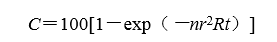
The surface coverage is measured using the fluorescence method. Before shot peening, a layer of fluorescent agent is applied to the surface of the part, and it is illuminated under a black light to ensure complete coverage. Then, the parts are shot peened. After shot peening, the parts are again illuminated under a black light, and if there is no or little fluorescence, the coverage is considered to be 100%. The specific process is illustrated in Figure 5.
(a) Effect of fluorescent coating on the surface of parts

(b) Parts before shot peening

(c) The part effect after shot blasting
Figure 5 Process of coverage testing by fluorescence method.
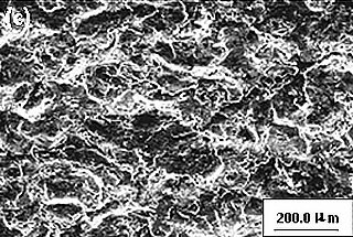
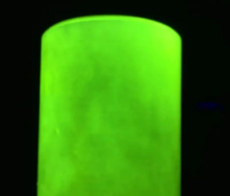
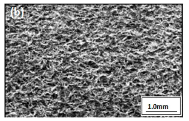
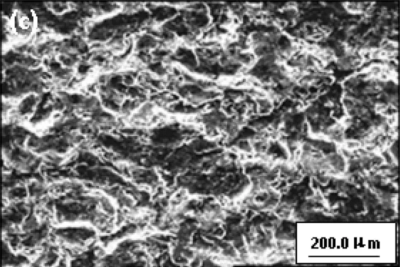
After selecting a part, its surface topography after blasting was further inspected as shown in Figure 6. Figures 6a and 6b show that the pellet craters are evenly distributed across the surface of the part, which indicates that no surface was missed, consistent with the fluorescence coverage test results. Upon magnification, as shown in Figure 6c, there were no cracks present on the surface and a denser, reinforced layer was formed.
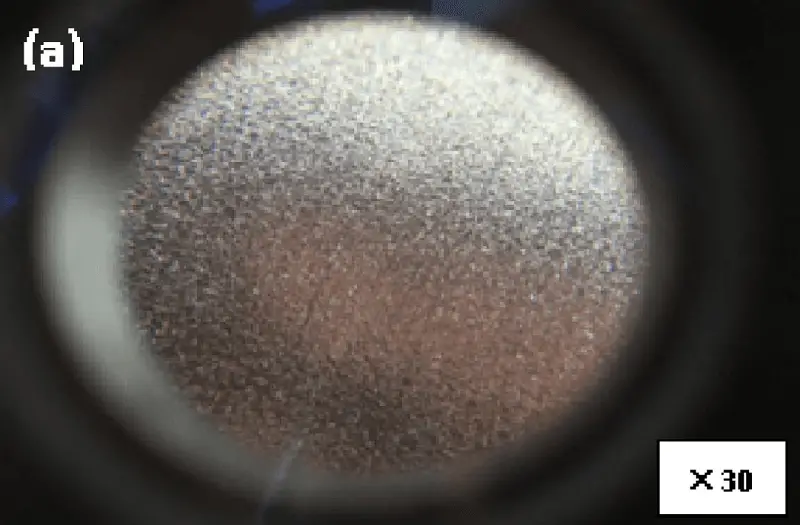
(a)
(b)
(c)
Fig. 6 Surface morphology after shot peening of aluminum barrel
A diamond stylus with a tip curvature radius of approximately 2μm is used to measure the surface roughness. The up-and-down movement of the stylus is converted into an electrical signal by an electrical length sensor. After amplification, filtering, and calculation, the surface roughness value is displayed on a meter and evaluated using the Ra value.
The surface roughness of 2A14 aluminum alloy was tested using a roughness meter, and the roughness before and after shot peening was measured, as shown in Table 2. When the surface roughness value of the non-shot peened part is low, it starts to increase after shot peening. This is because the surface hardness of the part is not very high, the surface is relatively uniform, and the impact energy generated by the projectiles is uneven, leading to the formation of larger pits on the relatively flat surface, causing an increase in surface roughness value.
However, when the surface roughness value of the shot peened part is high, the surface is already inhomogeneous and uneven. The uniform velocity of the projectiles causes plastic deformation of the surface, which actually flattens the rough and uneven surface.
Table 2 The effect of shot peening process on the surface roughness of aluminum alloy
| Surface roughness value before shot peening Ra/μm | 0.35 | 1.47 | 2.60 | 6.70 |
|---|---|---|---|---|
| Surface roughness value after shot peening Ra/μm[Shot peening strength 0.35mm (A)] | 2.20 | 2.60 | 3.30 | 5.67 |
| Surface roughness value before shot peening Ra/μm | 0.55 | 1.78 | 2.20 | 6.60 |
| Surface roughness value after shot peening Ra/μm[Shot peening strength 0.31mm (A)] | 1.96 | 2.10 | 2.80 | 4.96 |
| Surface roughness value before shot peening Ra/μm | 0.35 | 1.75 | 2.30 | 7.00 |
| Surface roughness value after shot peening Ra/μm[Shot peening strength 0.27mm (A)] | 1.65 | 1.85 | 2.50 | 4.85 |
Table 2 shows that, under different shot peening strengths, the greater the strength produced by the surface, the greater the impact on its relatively low strength surface. However, the overall trend of the impact on surface roughness is consistent.
The actual impact of shot peening on the surface of the part mainly depends on the energy transmission of the projectiles onto the surface, which is primarily determined by the mass and speed of the projectiles.
Figure 7 shows a schematic diagram of the force and acceleration direction of the projectile particles.
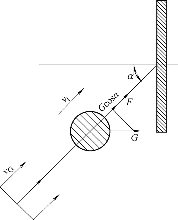
Figure 7 Force and direction of acceleration of the projectile particle
According to Newton’s second law, the differential equation of a projectile can be described as:
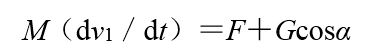
F is the drag force received by the projectile particles, which can be expressed as

In the formula,
The differential equation of the projectile particle:

In the formula,
According to the thermodynamic formula:

In the formula,
The mass of the projectile can be ignored, and the final differential equation for the movement of the projectile is:

Where c is the integral constant, when the boundary conditions t=0 and the projectile velocity v=0, c=1/vG, so

From the formula derived above, it can be deduced that the impact of various parameters of the shot peening process on surface performance can be attributed to:
(1) There are certain surfaces that cannot be sprayed, which suggests that the surface coverage is good and free of cracks, forming a relatively dense strengthening layer.
(2) The shot peening strength of the same type of projectile can alter the surface roughness of the part within a particular range. For example:
(3) The effect of various parameters of the shot peening process on the performance of the surface layer is derived from the differential equation of the projectile particles, and can be attributed to:
The stronger the shot peening process, the more impact it has on the surface compared to weaker processes, but the overall trend of the impact on surface roughness remains unchanged.

As the founder of MachineMFG, I have dedicated over a decade of my career to the metalworking industry. My extensive experience has allowed me to become an expert in the fields of sheet metal fabrication, machining, mechanical engineering, and machine tools for metals. I am constantly thinking, reading, and writing about these subjects, constantly striving to stay at the forefront of my field. Let my knowledge and expertise be an asset to your business.