This article explores the fascinating world of welding, from manual arc welding to advanced gas-shielded techniques. You’ll uncover the methods, benefits, and applications of various welding processes. Get ready to learn how these essential techniques shape our modern world!
Use the metal whose melting point is lower than the melting point of the base metal as the filler metal to heat the weldment and filler metal to the temperature between the melting point of the base metal and the melting point of the filler metal, so that the filler metal is liquid and wets the base metal, fills the joint gap and diffuses with the base metal to achieve welding.
Specific classification:
2.1 Common welding methods
2.1.1 Manual electrode arc welding
What is an arc?
The strong and lasting gas discharge between the workpiece and electrode is called arc.
To put it bluntly, it is just a gas discharge phenomenon.
However, the arc includes three parts: arc column area, cathode area and anode area.
Arc temperature:
Cathode area 2100 ℃,
Arc column 5700~7700 ℃
Anode area 2300 ℃
Heat in arc zone:
Anode accounts for 43%
Cathode area accounts for 36%
Arc column area accounts for 21%
What is arc welding?
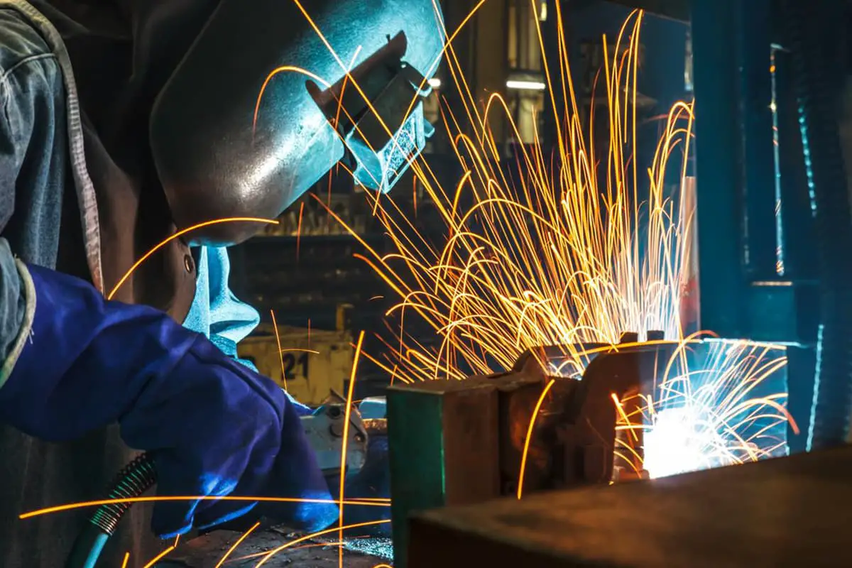
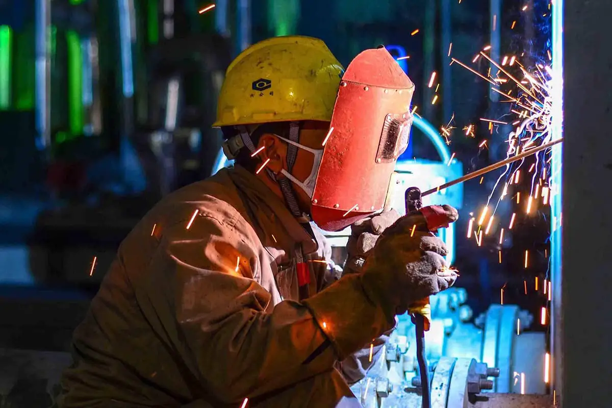
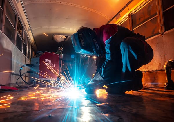
What is manual arc welding? To put it simply, arc welding is a welding method that uses arc combustion to provide heat source.
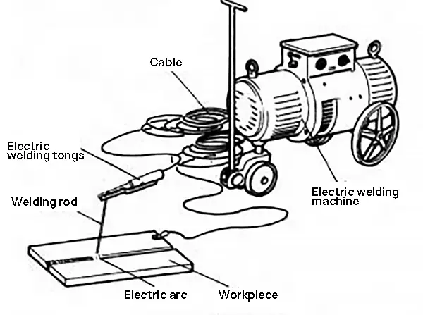
The electric arc welding method using manually operated welding rods is called manual electrode arc welding, which is called manual arc welding for short.
Schematic Diagram of Manual Arc Welding
How is manual electrode arc welding performed?
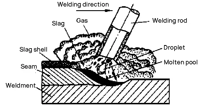
(1) The arc burns between the electrode and the weldment, and the heat of the arc makes the workpiece and the electrode melt into a molten pool at the same time;
(2) The electric arc melts or burns the coating of the electrode, producing slag and gas, which protect the molten metal and molten pool;
(3) When the arc moves forward, the subsequent molten pool cools and solidifies while new molten pool is continuously generated, thus forming a continuous weld.
Advantage of manual electrode arc welding:
Simple equipment, flexible operation and strong adaptability.
Disadvantage of manual electrode arc welding:
The production efficiency is low, the labor intensity is high, and the quality of welding joints is not easy to guarantee.
Application of manual electrode arc welding:
It can weld most metals, suitable for various welding positions, and can weld both thin and thick plates.
2.1.2 Automatic submerged arc welding
What is the commonly said submerged arc automatic welding?
Automatic welding – The welding action is automatically completed by the mechanical device.
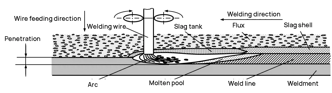
Submerged arc welding – Welding in which an arc burns under a granular flux layer.
(1) The flux flows out of the funnel and is evenly stacked on the welded part of the workpiece to form a flux layer (30-50mm);
(2) The continuously fed welding wire generates an arc between the welding wire and the weldment under the flux layer, melting the welding wire, workpiece and flux, forming a metal molten pool, and isolating them from the air;
(3) As the welding machine moves forward automatically, the arc continuously melts the metal, wire and flux of the weldment in front, while the edge behind the molten pool begins to cool and solidify to form a weld, and the liquid slag subsequently condenses to form a hard slag shell.
Why should a layer of flux be spread on the surface of the welding position?
It has the following three functions:
(1) Protective effect
Flux melts to form slag and gas, effectively isolating air, protecting droplet and molten pool, and preventing the burning of alloy elements;
(2) Metallurgical action
In the welding process, it plays the role of deoxidation and supplementing alloy elements;
(3) Improve welding process
Keep the arc burning steadily and make the weld beautiful.
What are the characteristics of automatic submerged arc welding?
What areas are they mainly used in?
Advantage of automatic submerged arc welding:
High production efficiency (5~times higher than manual arc welding);
Good working conditions (no spatter, low labor force).
Disadvantageof automatic submerged arc welding:
Not suitable for welding complex welds and narrow spaces;
The equipment is complex and the required welding current is large (small current will cause unstable arc);
Poor adaptability (applicable to flat welding, long straight weld and circumferential weld with larger diameter).
Application:
It is used for long straight weld and circumferential weld with large diameter of production and medium plate structure, such as boiler, pressure vessel, ship, etc.
In order to obtain reasonable weld formation and good welding quality, as well as improve the welding speed, multi wire submerged arc welding has emerged.
It is widely used in applications requiring high welding efficiency, such as wind power, marine engineering, shipbuilding, pressure vessels, heavy machinery, pipelines and other industries.
Multi power series multi-wire submerged arc welding:
It is mainly used for pipeline welding.
According to the application, it can be divided into external welding of long straight longitudinal seam of pipeline, internal welding of long straight longitudinal seam of pipeline, external welding of spiral welded pipe, internal welding of spiral welded pipe and other different types.
Single power parallel multi-wire submerged arc welding:
Greatly improve the production efficiency, increase the welding speed, reduce the flux consumption, reduce the heat input and deformation, save energy, make the primer more efficient and cover more smoothly.
2.1.3 Gas shielded welding
The arc welding using gas as the arc medium and protecting the arc and welding area is called gas shielded arc welding (GMAW).
Differences between consumable electrode and non consumable electrode gas shielded welding:
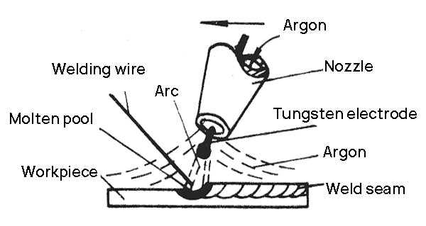
MIG/MAG: Directly feed the welding wire, which is both electrode and filler metal. TIG: Tungsten electrode is the electrode and does not melt; The welding wire is fed separately and used only as filler metal
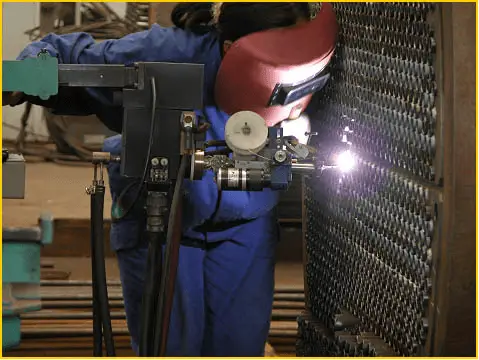
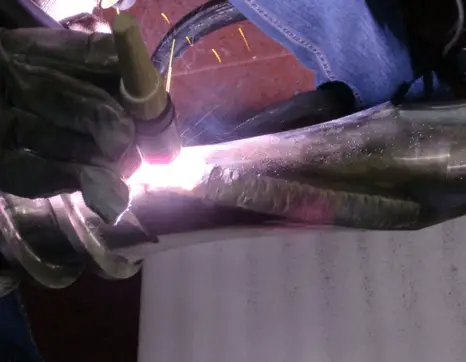
Argon arc welding
What are the characteristics of argon arc welding?
What are the main applications?
TIG
Tungsten electrode, manual wire feeding.
The welding wire is only the filler metal.
The welding wire does not pass the current, so there is no splash.
However, in order to avoid tungsten electrode melting and burning, which may cause tungsten contamination in the molten pool, the welding current is not easy to be too high.
Only thin plates less than 4mm can be welded.
MIG
Melting electrode, automatic wire feeding.
The welding wire is both an electrode and a filler metal.
There is no melting and burning loss of tungsten electrode.
The welding current can be adjusted in a wide range, so thin and medium-thick plates can be welded.
Advantage of argon arc welding
It can be welded in all directions;
Easy for observation and automatic control;
Good protection effect, stable arc and good welding quality;
It can weld almost all metals.
Disadvantage of argon arc welding
High argon cost;
The current density of argon arc welding is high, the light emitted is relatively strong, and the ultraviolet radiation generated by the arc is large, causing greater harm to the body;
The heat affected zone of argon arc welding is large, and the workpiece is prone to crack, pinhole, wear, scratch, undercut and other defects after repair;
Application of argon arc welding
It is mainly used for welding nonferrous metals and alloy steels that are easy to be oxidized (mainly welding of Al, Mg, Ti and their alloys and stainless steels).
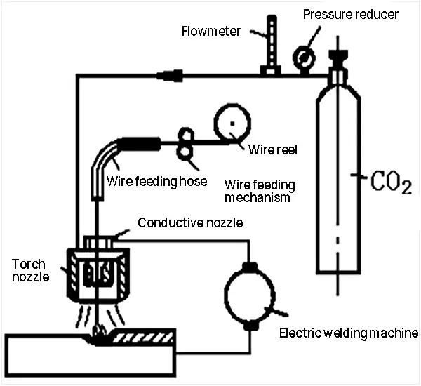
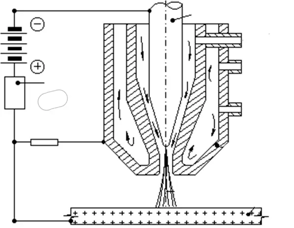
CO2 gas shielded arc welding
The principle of CO2 gas shielded arc welding is the same as that of MIG welding, except that the shielding gas is CO2.
The volume of CO gas in the molten pool and droplet expands rapidly and bursts, resulting in splashing.
It can oxidize metal and burn alloy elements, and can not weld nonferrous metals and alloy steel.
Structure diagram of CO2 gas shielded welding equipment
Advantage of CO2 gas shielded welding
Low cost (40%~50% of submerged arc welding and manual arc welding);
High efficiency (high current density, large penetration and fast welding speed);
Good welding quality (air flow cooling, small heat affected zone, small deformation);
Able to weld in all positions.
Disadvantage of CO2 gas shielded welding
Poor weld formation and large spatter;
Burn out alloy elements, easy to produce pores;
Poor wind resistance during welding, suitable for indoor operation.
Application of CO2 gas shielded welding
It is applicable to the welding of low carbon steel and low alloy steel sheet (0.8~4mm).
The welding wire containing deoxidizer must be used, and the DC connection must be reversed;
In addition, there shall be no wind during welding, and indoor welding is preferred.
2.1.4 Electroslag welding
Electric slag welding is a welding method that uses the resistance generated by the current passing through the slag to heat melt the welding wire and base metal to form a weld.
As for how electroslag welding is carried out, please see the following analysis:
(1) At the beginning, short-circuit the welding wire and the starting groove for arc starting;
(2) Continuously add a small amount of solid flux to melt it with the heat of the arc to form liquid slag;
(3) When the molten slag reaches a certain depth, increase the feeding speed of the welding wire and reduce the voltage, so that the welding wire is inserted into the slag pool and the arc is extinguished, thus turning into the electroslag welding process.
What are the characteristics of electroslag welding?
For what welding fields?
Advantage of electroslag welding
High productivity, no need to consider the thickness of weldment;
It is applicable to vertical welding and welding of 40~450mm thick plates, generally used for straight seam or circumferential seam welding, thick plate splicing, vertical welding of blast furnaces in steel plants, welding of large castings, forgings, etc.
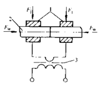
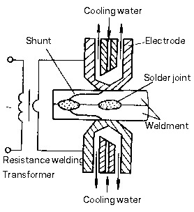
2.1.5 Resistance welding
To put it simply, the welding under pressure using resistance heat as the welding heat source is called resistance welding.
The weldment is assembled as a lap joint, and the cylindrical electrode is pressurized and energized to generate resistance heat to melt the weldment metal and form nuggets (welding spots).
Spot welding process and shunting phenomenon
Spot welding process: compression → power on (nugget formation) → power off (freezing) → removal pressure
Shunt phenomenon: when welding the second point, the existing welding point will conduct current, causing power loss. The current at the welding point is reduced, which affects the welding quality.
Prevent shunt: there should be a certain distance between two welding points.
The distance between two adjacent welding heads shall not be too small, and the minimum point distance is shown in the following table.
Workpiece thickness/mm
Point pitch/mm
Structural steel
Heat-resisting alloy
Aluminium alloy
0.5
10
8
15
1.0
12
10
15
1.5
14
12
20
2.0
16
14
25
3.0
20
18
30
4.0
24
22
35
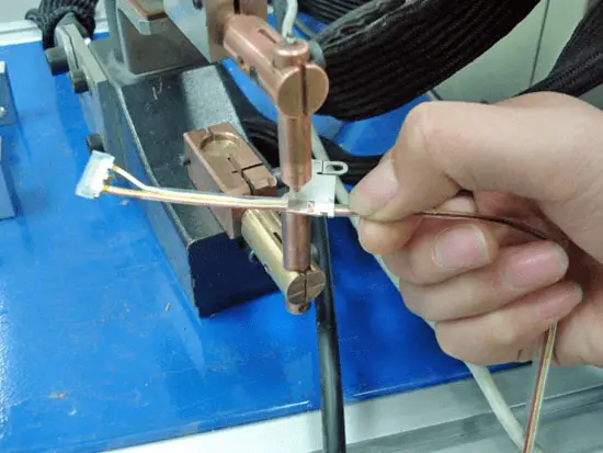
Application of spot welding
It is mainly used for sheet metal stamping structure and reinforcement components;
It is applicable to the welding of overlapping structural parts of thin plates with sealing requirements or high joint strength requirements, such as oil tank, water tank, etc.
2. Seam welding
The weldment is assembled into overlapping or diagonal joints and placed between two roller electrodes.
The roller pressurizes the weldment and rotates to drive the weldment to move forward.
The weldment is powered continuously or intermittently, and the weldment metal is melted by resistance heat to form a series of welding points.
Classification of seam welding
Form
Electric current
Electrode
Characteristic
Application
Continuous seam welding
Continuous conduction
continuous spin
Simple equipment and high productivity, but electrode wear is serious.
Small power welding non important structure (cylinder making, barrel, etc.)
stitch-and-seam welding
Intermittent continuity
continuous spin
Wide application (ferrous metal)
Step seam welding
Intermittent continuity
Intermittent rotation
Complex equipment, high requirements, low electrode wear and high welding quality.
It is mainly used for seam welding of magnesium and aluminum alloys.
Characteristic of seam welding
Solder joints overlap each other and flow diffluence is serious.
The current is about 1.5~2.0 times of that of spot welding;
The pressure is about 1.2~1.6 times of that of spot welding;
Therefore, high-power welding machine is required.
Apply pressure and use the roller as the electrode.
Application of seam welding
Seam welding is mainly used for thin-walled structures with regular weld seams and a thickness of less than 3mm and with sealing requirements;
Such as aircraft and automobile fuel tanks, various containers, steel radiators, etc.
3. Butt welding
A type of resistance welding method that uses resistance heat to weld two workpieces together along the entire end face is called butt resistance welding, or butt welding for short.
Butt welding can be divided into resistance butt welding and flash butt welding.
3.1 Resistance butt welding
(a) Resistance butt welding
Resistance butt welding refers to the method of pressing the end faces of two workpieces all the time, heating them to plastic state with resistance heat, and then rapidly applying upset pressure (or only maintaining the pressure during welding without upset pressure) to complete welding.
Characteristic of resistance butt welding
Simple operation and symmetrical joint shape;
The requirements for welding surface cleaning before welding are high;
The end face processing requirements are high, otherwise the welding quality is difficult to ensure.
Application of resistance butt welding
It is suitable for welding low-carbon steel bars and pipes with compact welding section, low strength requirements, diameter (or side length) less than 20mm, or non-ferrous metal bars and pipes less than 8mm (welding of rod shaped parts with similar end face shape and size).
3.2 Flash butt welding
(b) Flash butt welding
The weldment is assembled as a butt joint, the power is connected, and its section is gradually moved closer to local contact.
The metal in the section is melted and flies out under resistance heating, forming a flash.
When the end reaches the predetermined temperature within a certain depth range, the upsetting force is rapidly applied to complete the welding.
Less slag inclusion in the joint, good welding quality and high joint strength;
The requirements for cleaning the end face of the weldment before welding are not strict;
Flash butt welding has large metal loss, and the joint burrs after welding need to be processed and cleaned. The labor conditions are poor.
Application of flash butt welding
In principle, all metal materials that can be cast can be welded by flash butt welding.
For example, low carbon steel, high carbon steel, alloy steel, stainless steel;
Aluminum, copper, titanium and other non-ferrous metals and alloys;
It can also weld dissimilar alloy joints.
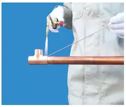
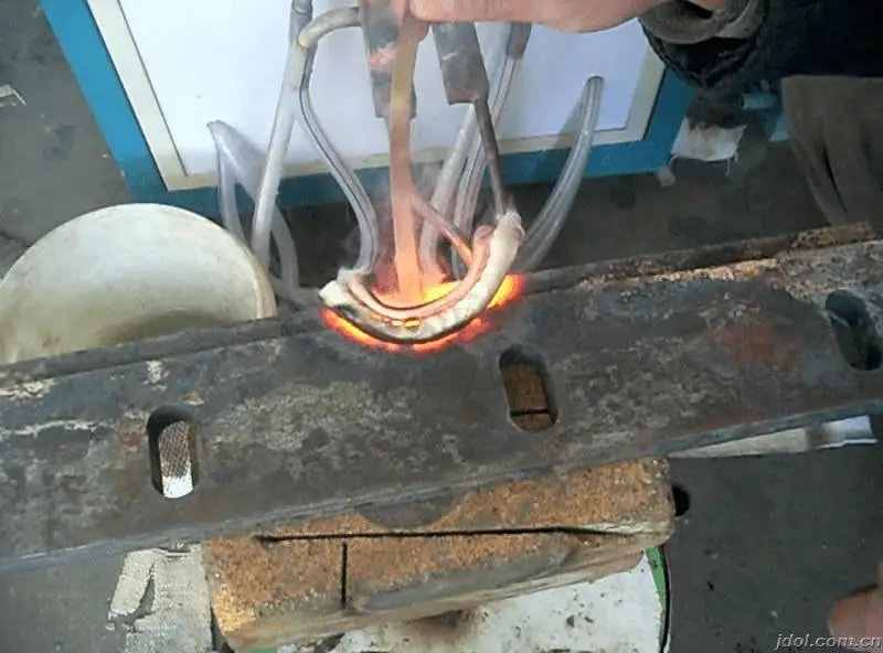
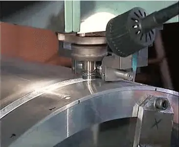
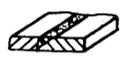
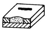
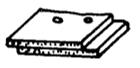
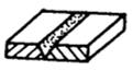
2.1.6. Brazing
(Soldering iron brazing)
(Flame brazing)
(Induction brazing)
Use the metal with a melting point lower than the weldment as the filler metal, heat the weldment (base metal) and filler metal to a temperature higher than the melting point of the filler metal and lower than the melting temperature of the base metal, melt and wet the base metal, fill the joint gap, and diffuse with the base metal to form a welded joint, which is called brazing.
Brazing process
Solder melting — liquid solder flowing into joint gap — mutual diffusion between solder and base metal — filling gap — forming joint after solidification
Characteristics of brazing
1) The melting point of the filler metal is lower than that of the base metal, and the base metal will not melt during brazing;
2) The composition of filler metal and base metal is very different;
3) The melted filler metal is sucked in by wetting and capillarity and kept in the base metal gap;
4) Metallurgical bonding is formed by mutual diffusion between liquid solder and solid base metal.
Advantage of brazing
The structure and properties of the base metal do not change (the base metal does not melt, only the filler metal melts);
Simple equipment, less production investment;
The heating temperature is low, the deformation is small, and the joint is smooth;
High productivity, can weld multiple weldments and joints at the same time;
It can be used to weld dissimilar metals or dissimilar materials, with no limit on the thickness difference of the workpiece.
Disadvantage of brazing
The brazed joint has low strength and poor heat resistance.
Classification of brazing
Type/characteristic
Soft soldering(tin, lead solder)
Brazing(Copper based and silver based solders)
Solder melting point
≤ 450℃
> 450℃
Performance Characteristics
Joint strength ≤ 100MPa, low working temperature
Joint strength > 200MPa, high working temperature
Application
It is used for welding instruments and conductive components with little stress.
It is used for welding of components, tools and tools with large force.
Application of brazing
It is mainly used for manufacturing precision instruments, electrical components, dissimilar metal components and welding of complex sheet structures, such as sandwich components, honeycomb structures, etc.
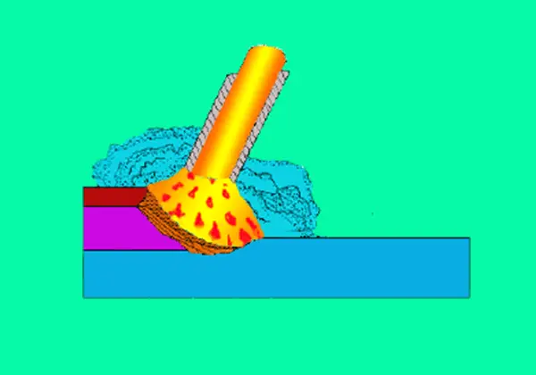
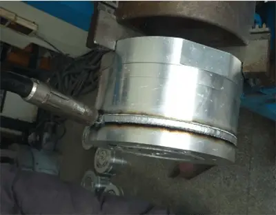
Friction welding is a pressure welding method that uses the heat generated by the friction between the surfaces of the weldment to make the end face reach the thermoplastic state, and then rapidly upsets to complete the welding.
Friction stir welding
Continuous drive friction welding
Inertia friction welding
Welding process of friction welding:
1) Relative movement of weldment;
2) The end face contact between the two weldments produces friction heat;
3) When the section reaches the thermoplastic state, press the top section quickly to complete the welding.
Advantage of friction welding:
High welding productivity, 5-6 times higher than flash butt welding;
Stable welding quality and high dimensional accuracy of weldments;
Low processing cost, power saving, no need for special cleaning of weldments;
Easy to realize mechanization and automation, simple operation;
No spark, arc and harmful gas.
Disadvantage of friction welding:
Large investment;
It is difficult to weld non-circular sections and the welding area is limited.
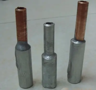
Application of friction welding:
It can be used for welding the same or different metal and different steel products, such as copper aluminum transition joints in the electric power industry, high-speed steel structural steel tools for metal cutting, serpentine pipes, valves, tractor bearings, etc.
The surface to be machined is heated by laser radiation, and the surface heat is directed to the internal diffusion through heat transfer to melt the workpiece and form a specific molten pool. The weld is formed after the molten pool solidifies.
Advantage of laser welding:
High welding speed and efficiency;
High welding precision, small deformation and easy automatic control;
No electrode is needed, so there is no electrode pollution.
Disadvantage of laser welding:
Large investment, small power, and limited weldable thickness;
It is difficult to align the welding point with the laser beam gathering area;
Rapid solidification of the weld bead may cause porosity.
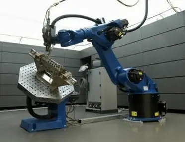
Application of laser welding:
It is mainly used for welding parts in precision manufacturing fields such as aerospace, shipbuilding, automobile and electronic industry.
To put it simply: the arc in which the arc column is compressed and the energy is highly concentrated, and the gas in the arc column is fully ionized, is called plasma arc, also called compression arc.
The gas is heated by the arc and initially ionized. When it passes through the water-cooled nozzle at high speed, it is compressed, increasing the energy density and ionization degree, and forming a plasma arc.
Because of the high heat and penetration force of the plasma arc, the workpiece at the welding point is melted to form a molten pool, so as to realize the welding of the workpiece.
Advantage of plasma arc welding:
High energy density, strong arc directivity and strong penetration ability;
The depth width ratio of the weld is large, and the heat affected zone is small;
Stable arc combustion (stable even when the current is small);
The welding cost is low, and when the welding thickness is small, there is no groove and no need to fill wire;
It has stable keyhole effect, and can better realize the free forming of single side welding and double sides.
Disadvantage of plasma arc welding:
Equipment is expensive;
Poor observability of arc action area;
The weldable thickness is limited (generally less than 25mm).
Application of plasma arc welding:
It is widely used in industrial production, especially in the welding of copper and copper alloys, titanium and titanium alloys, alloy steel, stainless steel, molybdenum and other metals used in military and cutting-edge industrial technologies such as aerospace, such as titanium alloy missile shells, and some thin-walled containers on aircraft.
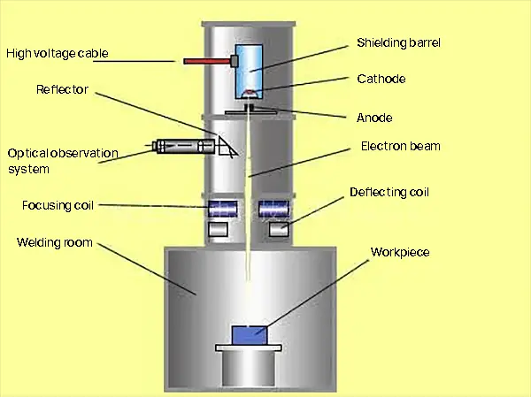
2.2.4 Electron beam welding
The method of welding by using the heat energy generated by the accelerated and focused electron beam bombarding the weldment placed in vacuum or non vacuum is called electron beam welding.
In other words, the heat required for welding is generated by electron beam bombarding the weldment.
Welding process:
1) The cathode of the electron gun emits electrons due to direct or indirect heating;
2) Under the acceleration of high-voltage electrostatic field, the electron beam with high energy density can be formed by focusing the electromagnetic field;
3) The high-energy density electron beam bombards the workpiece, and the huge kinetic energy is converted into heat energy to melt the weldment, forming a molten pool, and then complete the welding.
Advantage of electron beam welding:
Fast welding speed and high efficiency;
No groove, no welding wire, no flux, etc;
Low energy consumption, narrow heat affected zone, small welding deformation and excellent quality;
The penetration ability of electron beam is strong, and the depth width ratio of weld is large, which can reach 50:1.
Disadvantage of electron beam welding:
The equipment is complex and expensive;
The size and shape of weldments are often limited by the vacuum chamber;
The electron beam is easily interfered by stray electromagnetic field, which affects the welding quality.
Vacuum electron beam welding
Application of electron beam welding:
Suitable for fine welding of refractory metal, active metal and high purity metal.
It is widely used in the welding of nuclear energy, aviation, aerospace, automobile, pressure vessel, tool manufacturing and other industrial fields.
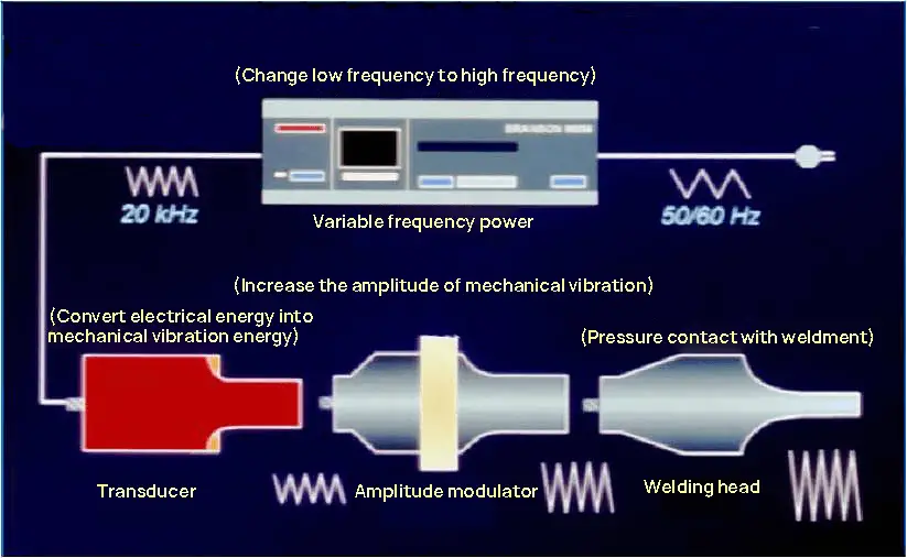
2.2.5 Ultrasonic welding
Ultrasonic welding is a method that uses the high-frequency oscillation of ultrasonic wave to locally heat and clean the workpiece joint, and then applies pressure to realize welding.
Welding process
1) Low frequency alternating current to high frequency alternating current;
4) Apply pressure, and the welding head contacts the workpiece for welding.
Advantage of ultrasonic welding:
Easy operation, fast welding speed and high production efficiency;
The requirements for the cleanliness of the workpiece surface are not high;
It is not necessary to add any binder, filler or solvent.
Disadvantage of ultrasonic welding:
It is only applicable to the welding of thin parts such as wire, foil, sheet, strip and strip;
In most cases, the joint form can only be lap joint.
Application of ultrasonic welding:
It is applicable to the welding of high conductivity, high thermal conductivity materials and a variety of composite materials, and is widely used in the welding of microelectronic devices and finishing fields.
2.2.6 High frequency welding
High frequency welding is a method that uses the resistance heat generated by high-frequency current in the workpiece to heat the surface layer of the welding area of the workpiece to a molten or near plastic state, and then applies (or does not apply) upset force to achieve metal bonding.
Skin effect: When the conductor is connected with AC current, most of the current flows only along the surface of the conductor.
Proximity effect: When high-frequency current flows in opposite directions between two conductors or in a reciprocating conductor, the current will concentrate on the flow near the conductor.
To put it simply, the skin effect is “the current goes to the surface”; Proximity effect is “current shortcut”.
Advantage of high frequency welding:
High welding speed and efficiency (the current is highly concentrated in the welding area);
A wide range of weldable materials can also be used to weld dissimilar metals;
Cleaning before welding is simple (fusion welding, with pressure effect, does not need to clean the joint surface).
Disadvantage of high frequency welding:
The joint assembly accuracy is required to be high;
High voltage and high frequency current are harmful to human body and other equipment.
Application of high frequency welding:
It is suitable for welding carbon steel, alloy steel, stainless steel, copper, aluminum, titanium and other dissimilar metals.
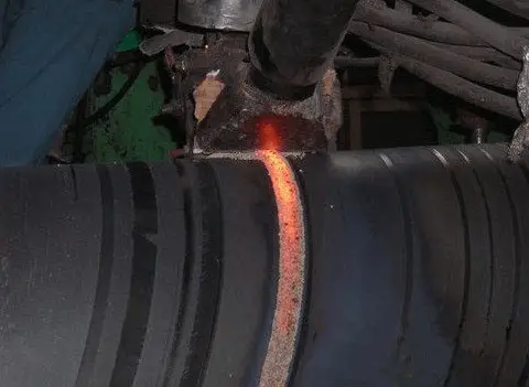
It is widely used for welding the longitudinal seam or spiral seam when manufacturing pipes.
2.2.7 Diffusion welding
Diffusion welding refers to the welding method of closely fitting the weldment, keeping it under a certain temperature and pressure for a period of time, and making use of the mutual diffusion of atoms between the contact surfaces to form a connection.
Welding process
Three stage model of diffusion welding
a) Rough initial contact b) Phase I: deformation and interface formation c) Phase II: grain boundary migration and micropore elimination d) Phase III: volume diffusion, micropore elimination
Physical welding display
Initial contact
Deformation and interface formation
Grain boundary migration and micropore disappearance
Volume diffusion and micropore elimination
Advantage of diffusion welding:
Multiple joints can be welded at one time;
The joint quality is good, and no machining is required after welding;
Small deformation of weldment (low pressure, overall heating of workpiece, cooling in furnace).
Disadvantage of diffusion welding:
Large investment and high cost;
Long welding time, time-consuming and labor-intensive surface preparation, and low productivity;
There is no reliable nondestructive testing method for weld quality.
Application of diffusion welding:
It is applicable to the welding of various dissimilar materials, special materials and special structures, and is widely used in aerospace, electronics, nuclear power and other industrial fields.
2.2.8 Explosive welding
Explosive welding is a method to realize welding by using the impact force generated by explosive explosion to cause rapid collision of workpieces.
Explosive welding is also a kind of pressure welding.
For welding of small workpieces, both parallel method and angle method can be used;
The parallel method is often used for large area welding.
The gap between the front sections of the two plates is too large, which will lead to excessive acceleration of the clad plate and excessive impact energy, resulting in damage and crack at the edge of the plate, thus reducing the effective area of the clad plate and consuming the plate.
Advantage of explosive welding:
Small investment and low cost;
Especially suitable for dissimilar metals and large area welding;
The process is simple, no complex cleaning is required, and the application is convenient.
Disadvantage of explosive welding:
It can only be used for welding of plane or cylinder structure;
Open air operation has low mechanization and affects the environment.
Application of explosive welding:
Suitable for welding dissimilar metals, such as aluminum, copper, titanium, nickel, tantalum, stainless steel and carbon steel, aluminum and copper welding.
It is widely used for the welding of conductive bus transition joints, heat exchanger tubes and tube sheets, and the manufacture of large-area composite plates.
3. Welding materials
What is welding material?
The general name of the materials consumed during welding is called welding materials; such as welding rod, welding wire, metal powder, welding flux, gas, etc.
Common welding materials
3.1 Welding rod
The electrode used in arc welding, which is coated with a protective coating, is referred to as the “electrode.”
The electrode is made up of a welding core and a coating.
1. Welding core
The core of the electrode, covered by the coating, is referred to as the welding core.
The welding core serves dual purposes: as an electrode that conducts current, and as a filler metal that joins with the melted base metal to create the weld.
2. Coating
The coating is a layer applied to the surface of the welding core after the raw materials, such as ore powder, ferroalloy powder, organic matter, and chemical products, have been prepared in a specific proportion.
Coating function:
1) Mechanical Protection (Combined Gas and Slag Protection)
Gas and slag are used to shield the air and prevent contact between the molten droplets, the molten pool metal, and the air.
The solidified slag forms a protective layer over the weld surface, which helps to prevent oxidation and nitriding of the high-temperature weld metal.
This process removes harmful elements and adds alloying elements.
3) Improving Welding Process Performance (Arc Stabilization)
The electric arc ignites easily and burns steadily, resulting in less spatter, a better-looking weld shape, and slag that is easy to remove. This process is suitable for all welding positions.
Composition of coating:
Name
Effect
Common raw materials
Arc stabilizer
Contains materials that are easy to ionize, improving the stability of the arc
(1) There are several oxide acids present in the drug skin, including FeO, SiO2, and TiO2, among others.
(2) The processability is good, and the weld formation is attractive with fine ripples.
(3) The slag exhibits strong oxidation.
(4) It works with both AC and DC power.
b. Basic electrode (low hydrogen electrode)
Characteristic:
(1) The skin of the drug contains higher levels of alkaline oxides, such as marble (CaCO3) and fluorite (CaF2).
(2) During welding, CO2 and HF are produced, which decreases the hydrogen content in the weld, earning it the nickname “low hydrogen electrode.”
(3) The weld is characterized by its high plasticity and toughness, although its processability and shape are not as good as those of the acid electrode. Typically, a DC reverse connection is used.
2) Classification according to the use of welding rods
Structural steel electrodes, heat-resistant steel electrodes, stainless steel electrodes, surfacing electrodes, low temperature steel electrodes, cast iron electrodes, nickel and nickel alloy electrodes, copper and copper alloy electrodes, aluminum and aluminum alloy electrodes, and special-purpose electrodes.
3) Classification according to chemical composition of drug skin
Titanium Oxide Electrode, Calcium Titanate Electrode, Ilmenite Electrode, Iron Oxide Electrode, Cellulose Electrode, Low Hydrogen Electrode, Graphite Electrode, and Base Electrode.
Model
The type of welding rod is determined based on the national standard for welding rods, and it is a means of expressing the primary characteristics of the reaction welding rod.
The model of welding rod includes the following meanings: type of welding rod, characteristics of welding rod (type of core metal, service temperature, chemical composition of deposited metal, tensile strength, etc.), coating type and welding power source.
Grade
Welding rod grade refers to the specific classification of welding rod products based on their intended use and performance characteristics.
The grades of welding electrodes are categorized into ten groups, including structural steel electrodes, heat-resistant steel electrodes, stainless steel electrodes, among others.
How to determine whether the welding rod used is reasonable?
To determine the appropriateness of the welding rod selection, it should be evaluated based on its technical performance indicators.
Process performance index
1) Arc stability
The arc is easy to ignite, and the degree of stable combustion (no arc break, drift, magnetic bias blow, etc.) is maintained.
2) Weld formation
Good forming means that the surface is smooth, the ripple is fine and beautiful, and the geometric shape and size of the weld are correct.
3) Adaptability of welding at various positions
All position welding adaptability – all electrodes can be used for flat welding, but some electrodes are not suitable for horizontal welding, vertical welding and overhead welding, so their all position welding performance is poor.
4) Spatter
The metal particles flying out of the droplet or molten pool during welding are called spatter.
Spatter rate = Mass of splash/(Welding rod quality before welding – welding rod quality after welding)*100%
5) Deslagging property
It refers to the difficulty of removing slag shells from the weld surface after welding.
6) Welding rod melting speed
It refers to the quality and length of the melted core in unit time when the electrode is applied; Relatively speaking, the greater the melting speed, the better.
7) Redness of electrode coating
It refers to the phenomenon that when the electrode is used in the second half, the coating becomes red, cracked or falls off due to the high temperature of the coating.
8) Welding fume
Selection principle of welding rod
a. The Equal Strength Principle states that the tensile strength of the metal deposited from the chosen electrode should be equal to or similar to that of the base metal being welded.
b. The Equal Toughness Principle states that the toughness of the metal deposited from the chosen electrode should be equal to or similar to that of the base metal being welded.
c. The Equal Composition Principle states that the chemical composition of the metal deposited from the chosen electrode should conform to or be close to that of the base metal.
Use and storage of welding rod
1. Drying of welding rod
The welding rod is prone to absorbing moisture from the atmosphere, which can negatively impact its performance and the quality of the weld.
Therefore, it is important to dry the welding rod (especially alkaline welding rods) prior to use.
Typically, the drying temperature for an acid electrode is between 75-150°C, and it should be kept at this temperature for 1-2 hours.
For an alkaline electrode, the drying temperature should be between 350-400°C, and it should be kept at this temperature for 1-2 hours.
It is important to note that the cumulative drying time of the welding rods should not exceed 3.
2. Storage of welding rods
1) Welding rods should be organized and stored by type, model, and specifications to prevent confusion.
2) The storage area should be well-ventilated and kept dry.
3) Low hydrogen electrodes, which are essential for critical welding structures, should be stored in a dedicated warehouse with a temperature above 5°C and relative humidity no higher than 60%.
4) To protect against moisture damage, the welding rods should be placed on a wooden rack with a minimum distance of 0.3 meters from the ground and walls.
3.2 Welding wire
The welding field has seen continuous advancements in technology, leading to an increase in mechanization and automation. This has resulted in higher production efficiency, improved welding quality, and better working conditions.
To further advance the mechanization and automation of welding, welding wires are utilized as the welding material.
What are welding wires referred to as in terms of welding materials?
The wire used as filler metal or for conducting electricity during welding is called welding wire.
Classification of welding wires
a. Classification according to manufacturing method and welding wire shape
It can be divided into solid wire and flux cored wire.
b. Classification according to the applicable welding method
It can be divided into submerged arc welding wire, gas shielded welding wire, electroslag welding wire, surfacing welding wire and gas welding wire.
c. Classification according to the properties of the metal materials to be welded
It can be divided into carbon steel welding wire, low alloy steel welding wire, stainless steel welding wire, nickel base alloy welding wire, cast iron welding wire and special alloy welding wire.
d. Classified by copper plating or not
Copper plated wire and non copper plated wire.
1. What kind of welding wire is called solid welding wire?
The wire is directly drawn to the target wire diameter. The welding wire without powder is called solid welding wire.
1.1 Production process of solid welding wire
1.2 Model of solid welding wire
1.3 Brand of solid welding wire
2. What kind of welding wire is flux cored?
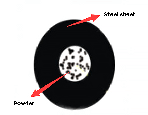
The thin steel strip is rolled into different sectional shapes, filled with powder, and then drawn into a kind of welding wire called flux cored wire.
The filled powder is called the core, and its effect is similar to that of the electrode coating.
2.1 Model of flux cored wire
2.2 Brand of flux cored wire
According to the wire structure, flux cored wire can be divided into: seam and seamless.
Seamless flux cored wire can be copper plated, with good performance and low cost, which has become the development direction in the future.
2.3 Production process of flux cored wire
For the production of seam flux cored wire, the “steel strip method” is commonly used;
For the production of seamless flux cored wire, the “steel pipe method” is commonly used.
a. Steel strip method
b. Steel tube method
3. Advantages and disadvantages of flux cored wire (compared with solid wire)
Advantages:
Small spatter, fast deposition speed, and high production efficiency.
Welding of various steels with strong adaptability.
Good process performance and a beautiful weld formation.
A large welding current can be used for welding in all positions.
It can be categorized into three types: Submerged Arc Welding Flux, Electroslag Welding Flux, and Surfacing Flux.
(2) Classification by Manufacturing Method
It can be divided into two categories: Smelting Flux and Non-Smelting Flux.
(3) Classification by Slag Alkalinity
It can be classified into three categories: Acid Flux, Neutral Flux, and Basic Flux.
a. Melting flux
The flux is created by melting various ingredients in a precise proportion in a furnace. The mixture is then granulated, dried, and screened while being cooled with water.
Characteristic:
1) It is not difficult to absorb moisture and typically does not require drying prior to use.
2) The flux that has not melted can be utilized again.
3) After being melted, it is cooled quickly, often taking the form of glass.
4) Only a limited amount of alloy elements can be added to the flux in the molten pool, as a large quantity cannot be transferred.
Melting flux
Main components:
SiO2:40~44%;
MnO:32~38%;
CaF2:3~7%;
CaO:≤8%.
b. Unmelted flux
The non-melting flux is obtained by mixing various powders according to a specific formula, adding a binder to form particles of a specific size, and then baking or sintering.
Bonding flux is a type of flux that is baked at low temperatures (below 400 ℃).
Sintered flux, on the other hand, is produced by sintering the flux at high temperatures (700 to 1000 ℃).
Characteristic:
1) The moisture absorption is relatively high, and it must be re-dried before use.
2) Easy to manufacture and highly applicable.
Sintered flux
Essential component(SJ101):SJ102
SiO2+TiO2:20~30% , 10~15%
CaO+MgO:25~35%, 35~45%
Al2O3+MnO:20~30%, 15~25%
CaF2:15~25%, 20~30%
Classification according to slag alkalinity:
(1) Acid flux (alkalinity B<1.0)
The slag is primarily composed of acid oxides and has excellent welding performance, resulting in a visually appealing weld formation. However, the weld metal has a high oxygen content, which results in low low-temperature impact toughness.
(2) Neutral flux (alkalinity 1.0 ~ 1.5)
The composition of the deposited metal is similar to that of the welding wire, with a reduced oxygen content in the weld metal.
(3) Alkaline flux (alkalinity B>1.5)
The primary components of slag are alkaline oxides and calcium fluoride. The weld metal is characterized by a low oxygen content, high impact toughness, and good tensile properties.
3.4 Solder
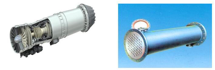
In modern, cutting-edge scientific and technological projects, such as aircraft plate fin radiators, rocket shells, engine nozzles, and others, they all require high precision and sharpness and cannot tolerate any defects. Almost all products must be of impeccable quality.
Brazing technology is widely used in these fields due to its advantages of low thermal impact, high precision, wide applicability, and high welding efficiency. It allows for the connection of multiple, complex, high-precision parts.
The brazing filler metal plays a crucial role in the brazing process.
In order to realize the combination of two materials (or parts), the filler added in or beside the gap is called filler metal.
1. What are the requirements for filler metal?
(1) A melting point that is appropriate (several tens of degrees lower than the base metal);
(2) Excellent wettability;
(3) Completely dissolved and integrated with the base metal;
(4) A uniform and stable composition;
(5) It is cost-effective and safe (containing fewer precious metals and toxic metals).
2. Classification of filler metals
1) Classification by melting point
“Soft solder” (also known as “fusible solder”) refers to solders with melting points lower than 450°C, including tin-lead solder, cadmium-silver solder, and lead-silver solder, among others.
“Brazing filler metal” (also referred to as “refractory filler metal”) refers to brazing fillers with melting points higher than 450°C, including aluminum-based, copper-based, silver-based, and nickel-based brazing fillers, among others.
2) Classification by main chemical components
According to the main metal elements of solder, it is called × base solder, such as brazing base solder, zinc base solder, etc.
3) Sort by shape
It can be divided into wire, rod, sheet, foil, powder or solder with special shape (such as annular solder or paste solder).
3. Application of filler metal
(1) Soft solder
It is primarily used for welding workpieces with low stress and low operating temperatures, such as connecting various electrical wires and soldering instruments, components of instruments, and other electronic circuits.
(2) Brazing filler metal
It is mainly used to weld workpieces with large force and high working temperature, such as bicycle frame, carbide cutter, drilling bit and other mechanical parts.
3.5 Flux
In order to obtain a better welding joint, it is necessary to reasonably match the brazing flux according to the different brazing filler metals to jointly use as the welding materials in the brazing process.
1. What is flux?
The flux used in brazing is called brazing flux, including paste, powder, etc.
2. What is the function of flux?
1) Remove the oxide layers from the surface of the solder and base metal.
2) Enhance the ability of the liquid solder to wet the weldments.
3) Prevent the weldment and liquid solder from being oxidized during the brazing process.
3. Requirements for flux
1) Ensure that there is enough capability to eliminate oxides from the surface of the base metal and filler metal.
2) The brazing flux’s melting point and minimum active temperature should be lower than the melting point of the brazing filler metal.
5) The flux and its residue should have minimal corrosion to the solder and base metal and should be easily removable.
4. Classification of flux
1) Soft Soldering Flux
The soldering flux used for brazing at temperatures below 450 ℃ can be divided into two types: inorganic and organic.
a. Inorganic Soft Solder (Corrosive Soft Solder) – It is composed of inorganic salts and acids and has strong chemical activity and thermal stability. This type of solder promotes the wetting of liquid solder to the base metal effectively, but its residue has a strong corrosive effect.
b. Organic Soldering Flux (Non-Corrosive Soldering Flux) – Its chemical activity is relatively weak and does not corrode the base metal. Examples of non-corrosive soldering fluxes include rosin, amine, and organic halides.
2) Brazing Flux
The flux used for brazing at temperatures above 450 ℃ has a high viscosity and requires high temperature activation.
It must be used at temperatures above 800 ℃, and its residue is difficult to remove.
Common brazing fluxes include borax, boric acid, and their mixtures. Adding fluoride and chloride of alkali and alkaline earth metals to borides can improve the wettability of borax and boric acid brazing fluxes, enhance oxide removal, and lower the melting and activation temperature of the brazing fluxes.
3.6 Gas
Welding gas primarily refers to the protective gas utilized in gas shielded welding processes, such as CO2 gas shielded welding and inert gas shielded welding, as well as the gas used in gas welding and cutting.
When welding, the shielding gas serves not only as a protective medium for the welding area, but also as the gas medium that generates the arc.
Gas welding and cutting are typically performed using a high-temperature flame generated from the combustion of gas, which provides a concentrated source of heat.
1. Common shielding gas
Emotional gas
Molecular gas
Compound gas
Argon, ammonia
Oxygen, nitrogen, hydrogen
carbon dioxide
2. Common gas for gas welding and cutting
That is, combustion supporting gas (O2) and combustible gas (acetylene C2H2).
3. Characteristics and uses of common welding gases
Gas
Symbol
Main properties
Application in welding
carbon dioxide
CO2
It has stable chemical property, does not burn or support combustion, can be decomposed into C0 and 0 at high temperature, and has certain oxidizability to metals. It can liquefy liquid CO2, absorb a lot of heat when evaporating, and solidify into solid CO2, commonly known as dry ice
Welding wire can be used as shielding gas during welding, such as CO2 gas shielded welding and C02+O2, C02+A and other mixed gas shielded welding
argon
Ar
Emotional gas, not active in chemical property, does not react with other elements at room temperature and high temperature
As a protective gas for mechanical protection during arc welding, plasma welding and cutting
oxygen
O2
Colorless gas, combustion supporting, very active under high temperature, directly combined with various elements. During welding, oxygen will oxidize metal elements when it enters the molten pool, which will play a harmful role
It can obtain extremely high temperature when mixed with combustible gas for welding and cutting, such as oxygen acetylene flame and hydrogen oxygen flame. Mix with argon, carbon dioxide, etc. in proportion, and conduct mixed gas shielded welding
B fast
CH2
Commonly known as calcium carbide gas, it is less soluble in water, soluble in alcohol, and largely soluble in acetone. It mixes with air and oxygen to form an explosive gas mixture. It burns in oxygen and emits high temperature and strong light
It can burn, is not active at normal temperature, and is very active at high temperature. It can be used as a reducing agent for metal ores and metal oxides. It can be melted in liquid metal during welding and precipitated when cooling, which is easy to form pores
When welding, it can be used as a reducing shielding gas, mixed with oxygen for combustion, and can be used as a heat source for gas welding
nitrogen
N2
The chemical property is not active, and it can be directly combined with hydrogen and oxygen at high temperature. It is harmful to enter the molten pool during welding. It does not react with copper basically and can be used as protective gas
During nitrogen arc welding, nitrogen is used as the shielding gas to weld copper and stainless steel. Nitrogen is also commonly used in plasma arc cutting as the outer protective gas
The heat input of butt weldment is higher than that of pure Ar
N2
99.9% purity
high
difference
difference
Produce porosity and nitride in steel
Flat
–
4. Application of mixed gas in welding
1)Ar + He
It can enhance weld penetration, decrease porosity, and enhance production efficiency.
It can be used on copper, aluminum, and their alloys, as well as titanium, zirconium, and other metals.
2)Ar + H2
The addition of hydrogen can raise the arc temperature, increase the heat input to the base metal, and reduce the formation of CO porosity.
The blended gas is a reducing agent and is ideal for welding nickel and its alloys, as well as stainless steel pipes.
3)Ar + N2
To enhance the arc temperature, you should add N2. A slight addition of N2 can enhance the arc rigidity and enhance the weld formation.
This technique is suitable for welding non-ferrous metals, such as copper and aluminum.
4)Ar + O2
The oxygen content in Ar+O2 (low content) is in the range of 1-5%, which enhances the wettability of the solution, minimizes porosity, and stabilizes the arc. This method is suitable for welding stainless steel, including low carbon steel and low alloy steel.
Ar+O2 (high content) has an oxygen content of approximately 20%, which increases production efficiency, reduces porosity, and enhances the impact toughness of welds. This method is appropriate for welding carbon steel and low alloy structural steel.
5)Ar + CO2
Stable arc, minimal spatter, simple to attain axial spray transfer, optimal weld formation, and a broad range of applications (suitable for both spray transfer and short circuit transfer).
6)Ar + CO2 + O2
It has been confirmed that the optimal gas mixture for welding low carbon and low alloy steel is 80% Argon, 15% Carbon Dioxide, and 5% Oxygen. This mixture provides excellent results in terms of weld formation, joint quality, metal transfer, and arc stability, and is highly satisfactory.
7)CO2 + O2
High deposition rate, deep penetration, low hydrogen content in the weld metal, strong welding with high current specifications, stable arc, and minimal spatter.
Common welding defects
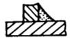
1. Shape defect of the weld (Fig. 6-1)
6-1
2. Unqualified weld size (Fig. 6-2)
6-2
3. Undercut (Fig. 6-3)
6-3
A groove created along the toe or root of a weld.
1) Excessive welding current;
2) The welding arc is too long;
3) The electrode angle is incorrect.
4. Incomplete penetration (Fig. 6-4)
6-4
Incomplete penetration of joint root during welding.
1) Incorrect groove size;
2) Improper selection of welding process parameters;
3) The electrode deviates from the groove center or the angle is incorrect.
5. No fusion (Fig. 6-5)
6-5
Incomplete fusion and bonding between weld metal and base metal or weld bead metal.
1) The welding current is too small or the welding speed is too high;
2) Unqualified cleaning before welding;
3) The electrode deviates from the weld center.
6. Crater (Fig. 6-6)
6-6
A depression formed at the end of a weld or at a joint.
7. Burnthrough (Fig. 6-7)
6-7
During welding, molten metal flows out from the back of the groove to form perforation.
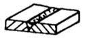
8. Overlap (Fig. 6-8)
A metal nodule formed when molten metal flows to the unmelted base metal outside the weld.
9. Slag inclusion and inclusion
Slag or non-metallic impurities left in the weld after welding.
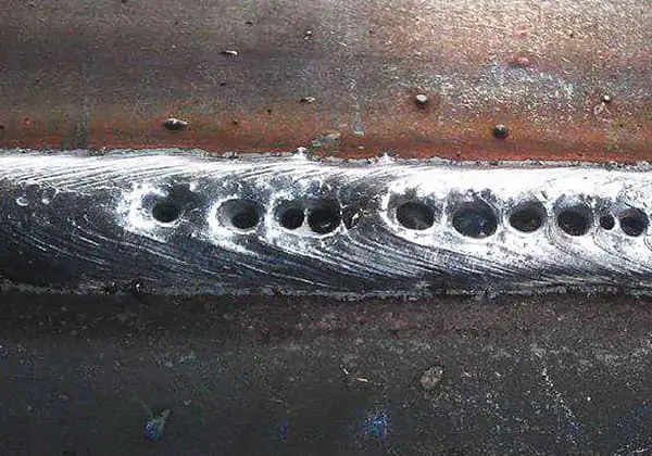
10. Air hole (Fig. 6-10)
A hole formed by gas remaining in the weld after welding.
Gas source forming pore:
1) Outside air;
2) Moisture;
3) Oil contamination and impurities.
11. Welding cracks (Fig. 6-11)
(1) According to welding position
(2) According to the crack direction
① The longitudinal crack is parallel to the weld
② Transverse crack perpendicular to weld
(3) According to the conditions of crack generation
① Hot crack Crack near the solidus temperature of weld and heat affected zone
② A crack cooled below the martensitic transformation temperature
③ Reheat crack
④ Ladder shaped cracks along the rolling direction of plate due to lamellar tearing
12. Splash
In CO2 welding, most of the melted metal from the welding wire is transferred to the weld pool, but some of it escapes and forms splatter. When using thick welding wire for CO2gas shielded welding with large parameters, the splatter can become particularly severe, with a rate as high as 20%.
This results in an inability to perform normal welding. The splatter is harmful, as it decreases welding efficiency, impacts the quality of the weld, and creates poor working conditions.
Splash hazard
The metal spatter loss in CO2 gas shielded welding can account for anywhere from 10% to 30-40% of the melted metal from the welding wire. The ideal loss is controlled to 2-4%.
This loss has several negative impacts:
It increases the consumption of welding wire and electricity, reducing efficiency and driving up costs.
The spattered metal can clog the contact nozzle and nozzle, causing feeding issues and undermining the stability of the arc, as well as reducing the protective effect of the shielding gas and the quality of the weld.
The spattered metal must be cleaned after welding, which adds to the overall working hours.
The spatter can even burn the welder’s clothing and skin, making the work environment hazardous.
Preventing and reducing metal spatter is a crucial consideration in CO2 gas shielded welding.
There is a correlation between the spatter rate and welding current for each diameter of welding wire in CO2 arc welding. In the low current area (short circuit transition area), the spatter rate is low. When the current enters the high current area (fine particle transition area), the spatter rate decreases again. However, the spatter rate is highest in the middle area.
The spatter rate is low when the welding current is less than 150A or more than 300A, and it is high between these two values. To minimize the spatter rate, it is best to avoid selecting welding currents in this high spatter rate area.
Once the welding current has been determined, the appropriate voltage should be chosen to ensure the lowest possible spatter rate.
Angle of the Welding Gun:
The spatter amount is at its minimum when the welding gun is held vertically. As the inclination angle of the gun increases, the spatter rate also increases. It is recommended not to tilt the welding gun forward or backward by more than 20 degrees.
Extension Length of the Welding Wire:
The spatter rate is also affected by the extension length of the welding wire. It is best to keep the length of the welding wire as short as possible to minimize spatter.
(2) Select appropriate welding wire material and shielding gas composition.
For example:
To minimize the generation of CO gas during welding, it is advisable to select steel welding wire with a low carbon content as much as possible.
The experience shows that when the carbon content in the welding wire is reduced to 0.04%, spatter can be significantly reduced.
Opt for tubular welding wire when welding.
The flux core in tubular welding wire includes deoxidizers and arc stabilizers, providing gas slag joint protection, making the welding process more stable, and reducing spatter significantly. The metal spatter rate of flux cored wire is approximately one-third of that of solid wire.
(3) CO2 mixture is used as shielding gas during long arc welding.
Although the spatter rate can be reduced through the proper selection of specification parameters and the use of the submerged arc method, the amount of spatter produced is still significant.
Incorporating a certain amount of Argon (Ar) gas into Carbon Dioxide (CO2) gas is the most effective method to reduce metal spatter that is caused by excessive welding of particles.
The physical and chemical properties of pure CO2 gas are altered when Argon is added to the mix.
As the ratio of Argon gas increases, the amount of spatter decreases gradually.
The CO2+Ar mixed gas not only reduces spatter but also improves weld formation, influencing weld penetration, height, and reinforcement.
When the Argon content reaches 60%, the size of the transfer droplets can be noticeably reduced and even spray transfer can be achieved, thus improving droplet transfer characteristics and reducing metal splash.
Diagram of welding defects
1. Weld scale
Repair method
Weld surface after descaling
2. Air hole
Repair method: Grind and remove the weld and re weld.
3. Crater needle shaped air hole
4. Air hole (sand hole)
5. Shrinkage cavity
6. End crack/weld crack
7. Appearance of bad welds
8. Overlap and flash
9. Undercut
10. Uneven weld
11. Poor appearance
Weld symbol and mark
1. Basic symbols
The weld symbol is made up of a basic symbol and a leader line, and if necessary, additional symbols, supplementary symbols, and symbols indicating the size of the weld.
The basic symbol represents the cross-sectional shape of the weld and is similar to the symbol for the cross-sectional shape of the weld found in Table 4-2.
2. Auxiliary symbols and supplementary symbols
Auxiliary symbols are symbols that indicate the shape characteristics of the weld’s surface. These symbols can be omitted if specifying the surface shape of the weld is not necessary.
Supplementary symbols are used to complement the symbols that represent certain characteristics of the weld surface. The methods of representing these symbols are shown in Table 4-3.
3. Size symbol of weld
If the size of the weld needs to be specified during design or production, it is indicated by the weld size symbol, as illustrated in Table 4-4.
Table 4-3 Auxiliary Symbols and Supplementary Symbols of Welds
Serial No
Name
Type
Auxiliary symbol
Explain
1
Plane symbol
Indicates that the weld surface is flush
2
Depression symbol
Denotes weld surface depression
3
Raised symbol
Indicating weld surface bulge
Serial No
Name
Type
Supplementary symbol
Explain
1
Symbol with backing plate
Indicates that there is a backing plate at the bottom of the weld
2
Three side weld symbol
It is required that the opening direction of the three side weld symbol is basically consistent with the actual direction of the three side weld
3
Peripheral weld symbol
Indicates welding around the workpiece
4
Site Symbols
Indicates welding at site or construction site
Table 4-4 Size Symbols of Welds
Symbol
Name
Sketch Map
δ
Sheet thickness
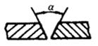
α
Groove angle
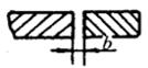
b
Butt clearance
p
Height of blunt edge
c
Weld width
K
Fillet size
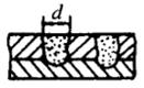
d
Nugget diameter
S
Effective thickness of weld
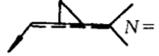
N
Number of identical welds symbol
K
Fillet size
R
Root radius
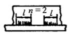
l
Weld length
n
Number of weld segments
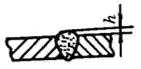
H
Groove depth
h
Weld reinforcement
β
Groove face angle
4. Leader
(1) The leader line is made up of an arrow line with an arrowhead, and two reference lines (one is a thin solid line, and the other is a dotted line).
(2) The dotted line can be located either above or below the thin solid line.
The datum line is usually parallel to the long side of the title block, but it can also be perpendicular to the long side of the title block if required.
The arrow line is drawn using a thin solid line, and the arrow points to the relevant weld seam. If necessary, the arrow line can be bent once.
If it is necessary to describe the welding method, a tail symbol can be added at the end of the reference line.
Fig. 4-1 Leader of weld symbol
5. Dimensioning method of common welds
(1) The dimensions across the cross-section of the weld are marked on the left side of the basic symbol.
(2) The dimensions along the length of the weld are marked on the right side of the basic symbol.
(3) The groove angle (α), groove face angle (β), and root gap (b) are marked either above or below the basic symbol.
(4) The same weld quantity and welding method code are indicated at the tail.
(5) If there is a large amount of dimension data to be marked and it becomes difficult to distinguish, corresponding dimension symbols can be added in front of the data to help clarify the information.
Table 12-1 Weld Symbols and Marking Methods
Welding joint and groove type
The common welded joints are butt joint, T-joint, corner joint and lap joint, as shown in the figure.
The selection of welded joints is primarily based on the structure of the welding, the thickness of the weldment, the strength requirements of the weld, and the conditions under which the construction is taking place.
Specified drawing method of weld
The line formed after welding the workpieces together is referred to as the weld seam.
If a simple representation of the weld is needed in a drawing, it can be depicted using a view, section view, or axonometric diagram.
The specific method of representing the weld in a drawing is shown in the figure.
Welding stress and deformation
Structural welding always results in welding deformation and stress.
During the welding process, the deformation and internal stress generated in the weldment that change over time are referred to as transient deformation and transient welding stress, respectively.
The deformation and stress that remain in the weldment after the temperature has cooled to room temperature after welding are known as residual welding deformation and residual welding stress, respectively.
3.1 Causes of welding stress and deformation
The root cause of welding stress and deformation is the uneven heating and cooling of the weld zone.
During the welding process, the weldment is heated locally, causing deformation to occur due to the metal’s characteristic of expanding and contracting.
However, the steel plate is a solid piece, and this expansion cannot occur freely.
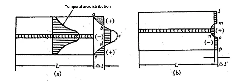
The end of the steel plate can only expand evenly by an amount of Δι.
Stress and deformation during butt welding of flat plate
(a) During welding; (b) After welding.
During cooling, the metal near the weld has undergone permanent compressive plastic deformation during welding and is also restricted by the metal on both sides.
In order to maintain overall consistency, Δι‘ is reduced evenly, which generates a certain amount of elastic tension in the weld area and a certain amount of elastic compression in the metal on both sides.
As a result, there is tensile stress in the weld zone and the surrounding metal, and there is compressive stress in the metal on both sides.
The stress in the member is in a state of balance. It can be observed that after butt welding a flat plate, the length of Δι‘ is shorter than it was before welding.
At the same time, tensile stress is generated in the weld zone and the metal on both sides, far from the weld, experiences compression stress.
In other words, the welding stress and deformation are maintained at room temperature and are known as residual welding stress and deformation.
3.2 Distribution, influence and elimination of welding residual stress
Welding stress can be divided into four categories: thermal stress, restraint stress, phase change stress, and residual welding stress. The residual welding stress is often very high.
In structures with thick welding, the residual welding stress can usually reach the yield strength of the material.
1. Classification of welding stress
(1) Longitudinal stress: Stress along the length of the weld.
(2) Transverse stress: Stress perpendicular to the length of the weld and parallel to the surface of the component.
(3) Stress in the thickness direction: Stress perpendicular to the length of the weld and the surface of the component.
2. Distribution of welding residual stress
(1) Longitudinal stress of weld σ x
The stress along the longitudinal direction of the weld is referred to as longitudinal stress (σ x).
The stress perpendicular to the longitudinal direction of the weld is referred to as transverse stress (σ y).
In the zone of compressive plastic deformation near the weld, the longitudinal stress (σ x) is tensile stress, which can typically reach the yield strength of the material.
Distribution of weld sections
(2) Transverse stress of weld
The figure illustrates the distribution of transverse stress (σy) in a plate weld of a certain length.
σy is tensile stress in the weld and the zone of compressive plastic deformation near the weld, while the two ends experience compressive stress.
The further away from the center of the weld, the quicker σy decreases.
In addition to the longitudinal and transverse stresses, there are also stresses along the thickness direction in thick plate welded structures.
The stress distribution in the three directions is highly uneven in the thickness direction.
Thick plate electroslag welding results in three axial tensile stresses at the center of the weld, which increase with the increase in plate thickness, but the surface experiences compressive stress.
3. Effect of welding residual stress
(1) Impact on the Strength and Stability of Compressive Parts
When the component is under tensile load, the residual welding stress will be added to the load stress, affecting the component’s strength.
(2) Influence on Brittle Fracture of Components
The increase in the nominal stress of the component, combined with the decrease in material toughness in the welding joint area and the presence of welding defects, will increase the likelihood of brittle fracture under low external loads.
The residual tensile stress in the weld zone can raise the average tensile stress value of the structure and reduce its fatigue life.
(4) Impact on Machining Accuracy and Dimensional Stability of Weldments
(5) Effect on Crack Propagation
When evaluating the crack state of the welding zone, the residual welding stress must be taken into consideration.
When calculating the stress intensity factor (KI) that drives crack growth, the residual stress (σr) is taken into account by using the equivalent tensile stress (σ3), which represents the contribution of residual stress to crack growth:
σ3 = αrσr
Where σr is related to the type of crack (through crack, buried crack, surface crack) and the direction of the crack (cracks parallel to the fusion line, cracks perpendicular to the fusion line, and fillet weld cracks).
4. Measures and methods to reduce and eliminate welding residual stress
(1) The key to reducing welding stress in design is to properly arrange the welds to avoid stress overlap and reduce peak stress.
① Minimize the number of welds and reduce the size and length of the welds.
② The welds should be spaced out sufficiently and avoid crossing as much as possible to prevent complex three-dimensional stress.
③ Welds should not be located in areas with high stress and abrupt changes in cross-section to avoid stress concentration.
④ The more flexible table type joint should be used, and flanging should replace the insertion tube.
Two Splicing Methods of Spherical Vessels (a) Staggered welds; (b) Weld intersection
(2) Techniques for Reducing Welding Stress in the Process
① Adopt a reasonable welding sequence and direction, and perform most welds with less rigidity.
② Minimize the temperature difference between the welding area and the entire structure to reduce internal welding stress. Use overall preheating and low linear energy.
③ Utilize hammer welding to reduce welding stress and deformation.
④ Decrease the hydrogen content and eliminate hydrogen.
(3) The method for eliminating residual stress primarily involves eliminating residual stress after welding. For boilers and pressure vessels with a pressure component thickness exceeding a certain size, post-welding heat treatment is required to eliminate internal stress.
Generally, welding causes deformation of the workpiece. If the deformation exceeds the acceptable limit, it will affect functionality.
The main cause of deformation is uneven heating and cooling of the weldment during welding.
During welding, the weldment is only heated in local areas, but the metal in the heated area cannot expand freely due to the metal with lower temperature around it.
When cooling, it cannot shrink freely due to containment by surrounding metal.
As a result, this part of the heated metal experiences tensile stress, while other parts of the metal experience compressive stress in balance with it.
When these stresses exceed the yield limit of the metal, welding deformation occurs.
Cracks appear when the strength limit of the metal is exceeded.
3.3 Forms, influencing factors and control methods of welding deformation
1. Welding deformation forms
The forms of welding deformation can be varied. The most common forms are five basic forms, or combinations of these forms.
Basic forms of welding deformation
Figure (a) illustrates the longitudinal and transverse shrinkage deformation in a flat plate after butt welding;
Figure (b) illustrates the angular deformation in a flat plate after docking;
Figure (c) illustrates the bending deformation caused by the deviation of the welding arrangement in a cylinder from the centroidal axis of the weldment;
Figure (d) illustrates the wavy deformation in a thin-walled weldment after welding.
Additionally, beam-column structures are susceptible to distortion during welding.
Shrinkage deformation and bending deformation are forms of overall deformation, while the other forms are considered local deformation.
2. Influencing factors of welding deformation
(1) The Effect of Weld Position on Welding Deformation
When the welds are symmetrically arranged in the structure, only longitudinal and transverse shortening occurs. However, if the welds are arranged asymmetrically in the structure, bending deformation will occur. Angular deformation will occur when the center of gravity of the weld section deviates from the center of gravity of the joint section.
(2) Influence of Structural Rigidity
Under the same force, structures with large rigidity have less deformation, while structures with low rigidity have more deformation. Welding deformation is always carried out in the direction with the least constraint of structural or weldment rigidity.
(3) Effect of Assembly and Welding Sequence
The rigidity constraint when welding a strip weld depends on the assembly and welding procedure. For structures with symmetrical sections and welds, a method of first assembling into a whole can be used. For complex welding structures, due to the multiple welds, the deformation caused by each weld affects the other welds, making it difficult to control. Thus, a procedure of partial assembly, welding, reassembly, and re-welding must be adopted to control the overall welding deformation.
(4) Other Influential Factors
Deformation is also closely related to groove type, assembly clearance, welding specifications, and welding method.
3. Methods for controlling welding deformation
To control and minimize welding deformation, it is essential to adopt appropriate design schemes and process measures.
(1) Reduce the number, length, and size of welds as much as possible while ensuring reasonable design for bearing capacity.
Arrange the position of the welds in a reasonable manner, such that all welds in the structure are symmetrical to, or as close as possible to, the neutral axis of the section. This will help to reduce the deformation of the weldment.
(2) Necessary Process Measures:
① Reserve Shrinkage Allowance:
When preparing the workpiece, add a suitable shrinkage allowance.
Typically, the longitudinal shrinkage of the weld is calculated based on the length of the weld and depends on factors such as groove, joint type, and plate thickness.
② Reverse Deformation Method:
Employ experience or calculation methods to determine the reverse deformation method.
Before welding, it’s crucial to assess the size and direction of potential deformation of the workpiece. To prevent residual deformation, place the weldment in the opposite direction of the deformation or apply artificial deformation beforehand during assembly. Proper control will help ensure that the workpiece attains the correct shape.
Anti deformation control of butt welding of 8~12mm thick steel plate
③ Select Appropriate Welding Methods and Specifications:
Utilize energy-concentrated heat sources and fast welding methods to reduce deformation.
④ Optimal Assembly and Welding Sequence:
Divide the large structure into smaller parts, assemble and weld each part separately, and then join the parts together into a complete whole.
⑤ Sturdy Fixation:
Fix and clamp the structure before welding to reduce deformation through external constraints. However, rigid clamping can prevent the free shrinkage of the weldment, leading to high internal stress within the component.
Therefore, it is crucial to carefully select the weldment material and structure.
⑥ Use reasonable welding sequence
4. Correction of welding deformation
Despite adopting deformation control methods, it is still challenging to avoid deformation after welding. When the deformation of the weldment exceeds the limits specified in the product technical requirements, it is necessary to perform post-weld correction to meet product quality standards.
The objective of correction is to induce new deformation in the welding components to counteract the deformation that occurred during welding. However, the correction process often increases internal stress in the components.
To avoid local fractures during correction, it’s advisable to relieve welding residual stress before correcting deformation. This will help to ensure the integrity and stability of the component.
Common Methods of Mechanical and Flame Correction in Production:
(1) Mechanical Correction Method:
The mechanical correction method involves using mechanical pressure or cold hammering to produce plastic deformation and correct welding deformation.
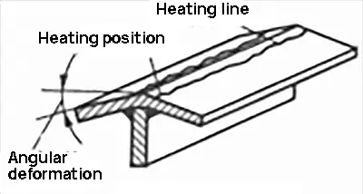
(2) Flame Correction Method:
The flame correction method uses the contraction caused by local heating with a flame to counteract elongation and deformation in the affected area. It is crucial to correctly identify the heating position, and the heating temperature for flame correction is typically between 600-800°C.
Correction of T-beam welding deformation by flame heating
Correction of upper arch deformation
Correction of angular deformation
(3) Pay Special Attention to Steel Type during Correction:
When performing correction, it’s important to be mindful of the type of steel being used:
Avoid using hammering for corrosion-resistant equipment to prevent stress corrosion.
Steels with a tendency towards intergranular corrosion and high hardening should not be corrected using flame correction.
For high strength steels with a high tendency towards cold cracking, it’s best to minimize the use of mechanical methods as they can easily cause cold work hardening.
Welding process elements and specifications
Welding technology is a critical factor in ensuring the quality of welded joints. In a manufacturing setting, the elements of the welding process are outlined in the detailed welding procedure guidelines.
The detailed welding procedure card is created based on the results of the corresponding welding procedure qualification test.
The elements specified in the detailed welding procedure card include:
(1) When using continuous AC or DC welding, the main electrical parameters in the welding specifications are the welding voltage and current.
(2) For pulse current welding, additional electrical parameters include the alternating frequency, on-off ratio, basic current, and peak current value.
(3) The principle for selecting welding specification parameters is to ensure proper penetration and a weld bead free from cracks, while also meeting the performance requirements specified in the technical conditions.
When selecting electrical parameters, it’s important to consider the impact of welding heat input on joint performance.
Refer to Table 4-8 for the selection of manual arc welding electrode diameters and the corresponding welding current range.
Table 4-8 Selection of electrode diameter and welding current for manual arc welding
Thickness of steel parts (mm)
1.5
2
3
4~5
6~8
9~12
12~15
16~20
>20
Electrode diameter (mm)
1.6
2
3
3~4
4
4~5
5
5~6
6~10
Welding current (A)
25~40
40~65
65~100
100~160
160~210
160~250
200~270
260~300
320~400
Table 4-9 Selection of double side submerged arc automatic welding specifications for beveled workpieces
Automatic submerged arc welding
Groove form
Diameter of welding wire (mm)
Weld sequence
welding current(A)
Arc voltage(V)
Welding speed(m/h)
14
5
positive
830~850
36~38
5
negative
600~620
36~38
16
5
positive
830~850
36~38
5
negative
600~620
36~38
18
5
positive
830~850
36~38
5
negative
600~620
36~38
22
6
positive
1050~1150
38~40
5
negative
600-620
36~38
24
6
positive
1100
38~40
5
negative
800
36~38
30
6
positive
100~1100
36~40
5
negative
900~1000
36~38
Welding cracks and control
Welding cracks refer to the separation of metal material (local fracture) within the weld joint due to welding-related causes, such as metallurgy, materials, or internal and external forces, during or after welding.
Cracks are one of the most dangerous welding defects, characterized by sharp ends and a much smaller separation width (opening displacement) than crack length.
Preventing welding cracks is a crucial aspect in the design and production of welding structures.
1. Classification of welding cracks
There are various types of welding cracks, and their classification methods have evolved as our understanding of the nature of cracks has deepened.
The following table provides a general classification based on the timing and location of cracks.
Table 4-11 Current crack classification method
Crack occurrence period
Occurrence site
Name
Welding process
Near the solid line
weld line
Solidification crack
Hot crack
Heat affected zone
Liquefaction crack
Below the solid phase line
weld line
Polygonal crack
Near recrystallization temperature T
Heat affected zone
High temperature plastic crack
Near room temperature
Heat affected zone
Cold crack
Heat affected zone and base metal rolling layer
Lamellar tearing
During re high temperature tempering heating after welding
Heat affected zone
Reheat crack
During use of corrosive medium
Welds, heat affected zone
Stress corrosion cracking
2. General conditions for welding crack formation
Cracks in high-strength steel bridges and shipbuilding steel structures are primarily cold cracks, accounting for 90% of all cracks. In petrochemical plants and power equipment, hot cracks are more prevalent. Pearlitic heat-resistant steel is prone to reheat cracks.
There are two main reasons for cracking:
(1) The stress and strain resulting from restraint is a major cause of cracking. A certain level of stress is required for cracking to occur, and the uneven heating process during welding can lead to tensile stress and strain in the joint due to the restraint of the entire structure during the welding cooling process.
(2) In a specific temperature range, due to the presence of brittleness factors, specific parts of the joint will crack under tensile stress.
3. Welding cracks
1. Hot cracks
(1) Characteristics of Hot Welding Cracks:
Hot cracks have the following morphological characteristics, which distinguish them from other cracks:
① Most cracks open on the weld surface and have an oxidized color.
② Cracks often occur at the junction of dendrites and along the longitudinal direction at the center of the weld cross-section.
③ Cracks are typically intergranular and exhibit high-temperature intergranular fracture properties.
④ They mostly occur during and after solidification.
(2) Formation Mechanism:
In the solidification process of welding, when there is low melting point eutectic present, the fast welding cooling speed can cause the grain boundary to be pulled apart and form cracks when the grain has solidified and the grain boundary is still in a liquid state with almost zero deformation resistance, and the welding tensile strain is high.
(3) Influencing Factors:
① Effect of Weld Chemical Composition:
Many eutectic crystals in welding are the result of welding metallurgical reactions.
Elements that can produce eutectic are elements that promote hot cracking.
Elements that can refine grains, produce high melting point compounds, or distribute low melting point eutectic in spherical or blocky forms are effective in inhibiting hot cracking.
Table 4-12 Effect of alloy elements on hot crack tendency
Seriously affect the formation of hot cracks
A small amount has little effect, while a large amount promotes hot cracking
Hot cracks are prone to form in deep and narrow welds due to the macro segregation that concentrates in the middle of the weld. Therefore, when performing automatic submerged arc welding on thick plates, it’s crucial to adjust the welding current and arc voltage proportion to ensure that the weld shape coefficient is greater than 1.3~1.5.
In manual arc welding, the weld section is small and the current is low, making it less likely to cause deep and narrow welds.
③ Influence of Welding Process and Weldment Structure:
The weldment structure and welding process directly impact the restraint of the welded joint, which is reflected in the welding tensile strain. Its effect on hot cracks is considered a mechanical factor.
(4) Measures to Prevent Hot Welding Cracks:
① The basic measures to prevent hot cracks are to tightly control the chemical composition of the weld, limit the content of carbon, sulfur, and phosphorus impurities, and add sufficient desulfurizers to the welding materials.
② Implement process measures such as preheating before welding, heat tracing, and welding with high wire energy (ensuring the weld shape factor is not too small).
③ Reduce the rigidity of the weldment as much as possible to minimize the internal stress of welding.
2. Cold cracks
(1) Characteristics of Cold Cracks:
Cold cracks are the most commonly produced welding defects when welding low-alloy high-strength steel, medium-alloy steel, medium-carbon steel, and other easily quenched steels.
① They occur after solidification of the weld metal, usually below the martensite transformation temperature or at room temperature.
② They mainly occur in the heat-affected zone and rarely in the weld zone.
③ They are often delayed.
(2) Cause: The root cause of cold cracks is the combined effect of low plasticity structure (hardening structure) in the heat-affected zone of the weldment, hydrogen in the welded joint, and welding stress.
(3) Influencing Factors:
① Hardening Effect:
When easily quenched steel is welded, the overheated zone forms a coarse martensite structure, reducing the plasticity of the metal in the heat-affected zone and increasing its brittleness. This makes it prone to cracking under high welding tensile stress.
② Role of Hydrogen:
Cold cracks induced by hydrogen exhibit the characteristics of delayed fracture, from latency to initiation, propagation, and cracking. The length of the delay time is related to the hydrogen concentration and the stress level of the welded joint.
TW – Austenitic transformation isothermal surface of the weld; TH – Austenitic transformation isothermal surface in heat affected zone Corresponding induced diffusion of hydrogen
③ Effect of Welding Stress:
Cold cracks are more likely to occur when welding stress is tensile stress and happens simultaneously with hydrogen precipitation and material hardening.
Welding of thick plates is more susceptible to cold cracks at the root. This is due to the rigidity of the thick plate and the fast cooling, which leads to the formation of a quenching structure and results in high welding stress.
3. Reheat cracks
(1) Characteristics of Reheat Cracks
① Reheat cracks occur in the temperature range of 540-930°C after post-welding stress relief heat treatment.
② The cracks propagate along the grain boundaries in the coarse grain zone of the heat affected zone.
③ Intergranular cracks with a branching shape will stop when they reach the fine grain area of the weld or base metal.
(2) Mechanism of Reheat Crack Formation
After the post-welding stress relief heat treatment and reheating, alloy carbides are dispersed and precipitated on dislocation lines after heat preservation at 550-700°C, which strengthens the intragranular structure.
At the same time, the grain boundary strength in the coarse grain area is low and its plasticity is poor.
During the reheating process, residual stress is released and the strength of the grain boundary is weaker than that of the grain, resulting in grain boundary cracking.
(3) Influencing Factors
There are several factors that affect reheat cracks:
These include chemical composition, restraint state, welding specifications, welding rod strength, stress relief specifications, and service temperature of the base metal.
① Chemical composition mainly affects the plasticity of grain boundaries in the heat affected zone.
② Restraint state and welding specifications affect welding residual stress.
③ Stress relief heat treatment specifications and service temperature mainly affect the plastic strain and degree of alloy carbide precipitation caused by reheating.
Therefore, the plastic deformation ability of the coarse grain zone in the heat affected zone, welding residual stress, and plastic strain caused by reheating are the three basic factors that influence reheat cracks.
(4) Measures to Prevent Reheat Cracks
Improve the plasticity of the coarse grain zone in the welding heat affected zone.
Reduce welding residual stress.
① The primary measure is to select a base metal with low sensitivity to reheat cracks.
② Take all necessary steps to reduce residual stress.
③ Avoid combining welding residual stress with other stresses, such as structural stress and thermal stress during reheating.
④ The use of low-matching welding materials helps absorb deformation.
⑤ Under the condition of ensuring stress relief, use the lowest possible reheat temperature and shortest holding time.
If possible, replace reheating with afterheat slightly lower than the preheating temperature for better results.
4. Lamellar tear
(1) Characteristics of Lamellar Tearing
① During rapid cooling of the weld, cracks parallel to the rolling surface of the base metal occur in the steel plate due to welding tensile stress in the direction of plate thickness. These cracks are known as lamellar tearing and often occur in T-shaped and K-shaped thick plate joints.
② Lamellar tearing is a type of crack that occurs at room temperature, typically after cooling to below 150°C or room temperature after welding. However, when structural restraint is very high and the steel is highly sensitive to lamellar tearing, it may also occur at temperatures between 300-250°C.
(a) Typical Position of Lamellar Tearing in “T” Joint
(b) Lamellar Tearing in Downcomer Joint of Boiler Drum
(2) Main Factors Causing Lamellar Tearing
① Influence of Inclusions
Inclusions are the main cause of steel anisotropy and the origin of lamellar tearing.
② Effect of Base Metal Properties
The plasticity and toughness of the metal matrix itself have a significant impact on lamellar tearing. Poor plasticity and toughness result in poor resistance to lamellar tearing.
③ Influence of Restraint Stress
All welding cracks occur under the action of tensile stress and lamellar tearing is no exception. Lamellar tearing is only caused when corner joints and T-joints are prone to forming large two-way restraint stress.
(3) Precautions for Lamellar Tearing
Lamellar tearing is difficult to repair, so preventing this defect is the main objective.
① When the welded joint is prone to causing lamellar tearing, evaluate the lamellar tearing sensitivity of the steel plate used and choose a steel plate with low sensitivity.
② Adopt a reasonable groove type to align the fusion line of the weld as closely as possible with the steel plate.
③ For steel grades that are sensitive to lamellar tearing, if possible, use welding materials with a lower strength grade, better plasticity, and toughness to reduce stress in the thickness direction of the steel plate.
④ For steel grades with high sensitivity to lamellar tearing, pre-deposit several layers of low strength weld metal on the steel plate surface at the welding groove.
Workmanship of welding structure
The arrangement of the weld seams in a welding structure has a significant impact on the quality and efficiency of the welded joints.
General principles of weld joint arrangement:
Weld Arrangement Should Facilitate Welding Operations
The weld arrangement must provide clear space for welders to work freely and for welding equipment to operate normally.
When performing submerged arc welding, consider the ease of storing the welding flux.
For spot welding and seam welding, the ease of inserting electrodes should be taken into consideration.
Weld Position Should Avoid Maximum Stress and Stress Concentration
For components with large and complex stress, welds should not be placed at positions with maximum stress and stress concentration.
For instance, the splicing weld for a large-span welded steel beam and plate should not be located in the center of the beam, but instead, an additional weld should be added.
Decentralized Weld Arrangement Reduces Welding Stress and Deformation
Dense or cross welds can cause overheating, enlarge the heat affected zone, and weaken the structure.
Typically, the distance between two welds should be more than three times the plate thickness and not less than 100mm.
Welds Should Avoid Machined Surfaces Whenever Possible
If machining is necessary before welding, the weld position should be designed as far away from the machined surface as possible.
On surfaces with high machining requirements, it is best to avoid setting welds.
Welding End Transition Design Should Be Smooth and Avoid Melting
To prevent melting during welding, there should be no sharp angles at the end of the weldment. The transition between two welding joints should be smooth to avoid stress concentration.
GB/T 19804-2005/ISO 13920:1996
(1) General dimensional tolerance and geometric tolerance range of welded structures
Table 1 Linear Dimension Tolerance Unit: mm
Range of nominal size l
Tolerance class
A
B
C
D
2~30
Tolerance t
± 1
>30~120
± 1
± 2
± 3
± 4
>120~400
± 1
± 2
± 4
± 7
>400~1000
± 2
± 3
± 9
± 6
>1000~2000
±3
±4
±8
±12
>2000~4000
±4
±6
±11
±16
>4000-~8000
±5
±8
±14
±21
>8000~12000
±6
±10
±18
±27
>12000~16000
±7
±12
±21
±32
>16000~20000
±8
±14
±24
±36
>20000
±9
±16
±27
±40
(2) Angular dimension tolerance
The shorter side of the angle should be used as the reference edge and its length can be extended to a designated reference point. In this case, the datum point should be marked on the drawing. Refer to Table 2 for tolerances. Figures 1 to 5 provide specific examples.
Table 2 Tolerance of Angular Dimensions
Tolerance class
Nominal size (workpiece length or short side length) range/mm
The straightness, flatness, and parallelism tolerances listed in Table 3 apply to all dimensions of weldments, welded assemblies, or welded components, as well as the dimensions marked on the drawings. Coaxiality and symmetry tolerances are not specified. If these tolerances are necessary for production, they should be marked on the drawing according to GB/T1182.
Table 3 Tolerances for Straightness, Flatness and Parallelism Unit: mm
Public grade
E
F
G
H
Range of nominal dimension l (corresponding to the longer side of the surface)
>30~120
Tolerance t
± 0.5
±1
± 1.5
± 2.5
>120~400
±1
± 1.5
±3
±5
>400~1000
±1.5
±3
± 5.5
±9
>1000~-2000
±2
± 4.5
±9
±14
>2000~4000
±3
±6
±11
±18
>4000~8000
±4
±8
±16
±26
>8000~-12000
±5
±10
± 20
±32
>12000~16000
±6
±12
±22
±36
>16000~20000
±7
±14
± 25
±40
>20000
±8
±16
± 25
±40
Inspection of sheet metal riveting welding section
1. Raw material inspection standard
1.1 Metal materials
1.1.1 Sheet Metal Thickness and Quality The thickness and quality of the sheet metal must comply with the national standard, and the performance test report and manufacturer’s certificate for the sheet metal used must be provided.
1.1.2 Material Appearance The material must be flat, free of rust, cracks, and deformations.
1.1.3 Dimensions The dimensions must conform to the drawings or technical requirements. If not provided by our company, they must comply with the current national standards.
1.2 Plastic powder
1.2.1 Plastic Powder Consistency The entire batch of plastic powder must have good consistency, with a factory certificate and inspection report that includes the powder number, color number, and various inspection parameters.
1.2.2 Trial Requirements The plastic powder must meet product requirements after trial, including color, luster, leveling, adhesion, etc.
1.3 General hardware and fasteners
1.3.1 Appearance The surface must be free of embroideries and burrs, and the appearance of the entire batch of incoming materials must be consistent.
1.3.2 Size The size must meet the requirements of the drawings and national standards.
1.3.3 Performance The performance must meet product requirements after trial assembly and service performance.
2. Process quality inspection standards
2.1 Blanking inspection standard
All sharp corners, edges, and rough surfaces that may cause harm must be deburred.
The burrs produced from stamping should not have any noticeable protrusions, indentations, roughness, scratches, rust, or other imperfections on the exposed and visible surfaces of door panels and panels.
Burrs: After blanking, the burr height must not exceed 5% of the plate thickness (t).
Scratches and knife marks: The product is considered qualified if it does not have any visible scratches when touched by hand and the scratches should not be greater than 0.1.
The specifications for surface tolerance are presented in Table I.
Attached Table 1. Flatness Tolerance Requirements
Surface dimension (mm)
Deformation size (mm)
Below 3
Less than ±0.2
More than 3 but less than 30
Less than ±0.3
More than 30 but less than 400
Less than ±0.5
More than 400 but less than 1000
Less than ±1.0
More than 1000 but less than 2000
Below ±1.5
More than 2000 but less than 4000
Less than ± 2.0
2.2 Bending inspection standard
2.2.1 Burr: The height of the extruded burr after bending must not exceed 10% of the plate thickness (t). Unless otherwise specified, the bending radius must be R1.
2.2.2 Indentation: The product may have visible creases, but they should not be noticeable when touched. The product can be compared to a reference sample.
2.2.3 Bending Deformation Standards: The standards for bending deformation must be in accordance with Tables II, III, and IV.
2.2.4 Bending Direction and Size: The direction and size of the bending must be consistent with the drawings.
Attached Table 2: Diagonal Tolerance Requirements
Diagonal dimension (mm)
Dimension difference of diagonal (mm)
Below 300
Below ±0.3
More than 300 but less than 600
Less than ±0.6
More than 600 but less than 900
Less than ±0.9
More than 900 but less than 1200
Less than ±1.2
More than 1200 but less than 1500
Less than ± 1.5
More than 1500 but less than 1800
Less than ± 1.8
More than 1800 but less than 2100
Below±2.1
More than 2100 but less than 2400
Below±2.4
Over 2400 to 2700
Below ±2.7
2.3 Angle:
The angle must be checked and measured according to the specifications in the drawings. The tolerance for the angle is presented in Table III.
Limit deviation value of angular dimension
Limit deviation value of angular dimension
Tolerance class
Basic size segmentation
0-10
>10-50
>50-120
>120-400
>400
Precision f
± 1 °
±30’
+20’
±10’
±5’
Medium m
Coarse c
+1°30
+1°
+30
+15′
+10’
Coarsest v
+3°
±2°
+1°
+30’
+20’
2.4 Inspection standards for sheet metal workpieces
The dimensions shall be inspected according to the drawing requirements, and the dimensional tolerance is shown in Table IV.
2.5.1 Welds must be strong and consistent, without defects such as inadequate welding, cracks, incomplete penetration, welding penetration, notches, or undercuts.
The length and height of the welds must not exceed 10% of the required length and height.
2.5.2 Welding Point Requirements: The length of each welding point must be between 8mm and 12mm, with a distance of 200 ± 20mm between two welding points. The V welding point must be symmetrical and have uniform upper and lower positions.
If the processing drawings have special requirements for welding points, these requirements take precedence.
2.5.3 The distance between spot welds must be less than 50mm, the spot weld diameter must be less than φ5, and the spot welds must be evenly spaced. The indentation depth on the spot welds must not exceed 15% of the actual plate thickness, and no noticeable welding scars should remain after welding.
2.5.4 After welding, no other non-welding parts can be damaged by welding slag or arc, and all surface welding slag and spatter must be removed.
2.5.5 After welding, the outer surface of the parts must be free of slag inclusions, air holes, overlaps, bulges, depressions, or any other defects. The defects on the inner surface must not be noticeable and must not affect the assembly.
The post-welding stress of important parts such as door panels and panels must also be relieved to prevent workpiece deformation.
2.5.6 The external surface of the welding parts must be smoothed by grinding. For powder-sprayed parts and electroplated parts, the roughness after grinding must be Ra3.2-6.3, and for painted parts, it must be Ra6.3-12.5.
3. Inspection standards for sprayed parts
3.1 Appearance inspection (inspection method: visual inspection and hand feeling)
3.1.1 Before spraying, the workpiece surface must be degreased, derusted, phosphatized, and cleaned.
3.1.2 The workpiece surface must not have any watermarks or residual cleaning solution.
3.1.3 The workpiece surface must not have any oil stains, dust, fibers, or other undesirable phenomena that may affect the quality or adhesion of the sprayed surface.
3.1.4 The color must match the sample plate (no obvious color difference should be observed under natural light or a 60w fluorescent lamp for normal vision), and there must be no color difference for the same batch of products (note: color difference includes color and glossiness).
3.1.5 The coating surface must be smooth, flat, and even, and must not have the following defects:
Non-drying and back sticking: the surface appears dry, but is actually not completely dry, with (or susceptible to) grain marks on the surface and fabric fluff;
Sagging: there are liquid protrusions on the surface that are bead-shaped at the top;
Particles: the surface has a sand-like appearance and feels blocked to the touch;
Orange peel: the surface appears uneven and irregular like the skin of an orange;
Bottom leakage: the surface is transparent and the color of the substrate is visible;
Pits: small holes (pits) on the surface due to shrinkage, also called pinholes;
With pattern: the surface color varies in depth, showing patterns;
Wrinkle: the surface is locally piled and raised, showing wrinkles (except for wrinkle powder);
Inclusion: there are foreign objects in the coating;
Mechanical damage: scratches, abrasions, and bruises caused by external forces.
3.1.6 Surface Grade Classification Standards:
Grade A Surface: the external surface that is often seen after assembly, such as the cabinet panel, cabinet door, sides around the cabinet, top surface visible to ordinary people, and low surface visible without bending over.
Grade B Surface: the surface that is seldom seen but can be seen under certain conditions, such as the inner accessories, reinforcing ribs, and inner side of the gate that can be seen after opening.
Grade C Surface: the surface that is generally not seen or only seen during assembly, such as the contact surface between the carriage and the guide rail in the cabinet.
3.1.7 Inspection Conditions:
Light source requirements: Arctic daylight or indoor high-efficiency fluorescent lamp with two light sources (illuminance of 1000 lumens).
Visual inspection distance: 300mm for Grade A surface, 500mm for Grade B surface, and 1000mm for Grade C surface.
3.1.8 Inspection Standards:
The grade surface of the product must be distinguished according to the light source standard.
The coating film of all grade surfaces must not have any base material exposure, peeling, or other defects, and all surfaces must not have any scratches, bubbles, pinholes, powder accumulation, or other undesirable phenomena.
Color and pattern: the manufacturer must make samples as required, which must be confirmed by both parties.
Acceptance must be conducted according to the sample, without any obvious color difference (no more than 3 degrees), and the grain must match the sample.
The inspection must be conducted at the eye distance level, scanning at a speed of 3m/min.
3.1.9 Appearance Defect Standard:
See Attached Table 5 for the determination criteria.
Attached Table 5: Judgment Criteria for Surface Defects
Serial No
Defect type
Specification value (mm)
Area limit (mm2)
Inspection tools
Below 100
100-300
Above 300
A
B
C
A
B
C
AB
C
1
Abrasion, scratch, scratch
10 in length and less than 0.1 in width
0
2
2
0
3
1
4
4
Vernier tape
Length: 10, width: less than 0.15
0
1
1
0
2
21
3
3
15 in length and less than 0.1 in width
0
0
0
0
1
1
1
2
2
More than 0.15 wide
0
0
0
0
0
0
1
1
2
Foreign particle
Below 1
1
2
3
2
3
4
3
4
5
vernier
Below 1.5
0
1
2
1
2
3
2
3
4
Below 2
0
0
1
0
1
2
0
2
3
3
Shrinkage cavity
Below φ0.3
1
1
2
2
2
3
3
3
4
vernier
Below φ0.5
0
0
1
1
1
2
2
2
3
Above φ0.5
0
0
0
0
0
1
0
0
2
4
Black dot White dot Other color dots
Below 0.3
1
2
2
2
3
3
3
4
4
vernier
5.
Bending indentation
3 in length and less than 0.2 in width.
2
3
3
3
4
4
4
5.
5.
vernier
Length: 5, width: less than 0.2
1
2
2
2
3
3
3
4
4
More than 5 long
0
1
1
1
2
2
2
3
3
More than 0.2 wide.
0
0
1
1
0
2
0
2
3
6.
color and lustre
–
In addition to the upper and lower limits of the specified color palette, no mixed colors and shedding are allowed
Visual inspection
7.
gloss
–
There shall be no unevenness as specified in the design.
Visual inspection
8.
Oil stains and stains
–
No
Visual inspection
Remarks: The values in the bold black boxes are the judgment criteria. For example, “2” means that under the specified conditions, no more than 2 points are allowed.:
3.2 Coating thickness inspection standard
unit: µm
Project
Outdoor powder
Indoor powder
Painting
Test method
Product surface thickness
60~120
50~100
40~70
Coating thickness gauge
Inside thickness of product
60~100
50~80
30~60
Coating thickness gauge
3.3 Coating gloss and color detection
3.3.1 Fabrication of spraying color plate
A. During baking, two color plates should be created for each furnace to conduct a performance test. The metal plate used should be of the same material as the product, with a size of 80 × 120, and it should be added to the product under normal conditions. The powder number, curing conditions, date, and time should be clearly marked and signed by the Quality Engineer (QE).
After confirmation, the number, name, and registration should be recorded and managed. One plate should be kept for testing purposes and the other for archiving.
B. The validity period of the color plate used in the powder spray manufacturing process is two years, and it should be stored at room temperature (70 ± 15%) in an environment that is free from light. The storage environment should also maintain a consistent temperature and humidity level.
3.3.2 Gloss and color detection method
Gloss: The gloss should be evaluated using a glossmeter with an incidence angle of 60° and an error tolerance of ± 5%. If the results meet these criteria, the product is considered qualified.
Color: The color of the product must match the design drawing or be no significantly different from the standard color plate.
3.4 Coating adhesion test
3.4.1 Baige test method
After the spraying process, a furnace color plate should be taken and 11 layers of coating should be carved on the surface in both a vertical and horizontal manner, with an interval of 1mm. The carving should be done with appropriate strength, such that the scratch does not reach the substrate.
Next, the coating surface should be divided into 100 squares, and then secured with a strong transparent adhesive at a 45-degree angle. The adhesive should then be suddenly removed. At this point, the contents within each square should be checked to see if they have fallen off.
Each grid represents 1 percent, and the acceptance standard is Level 5, meaning that the number of squares with falling contents should not exceed 5.
3.4.2 Assessment method
Grade 0: There should be no shedding at any intersections.
Grade 1: Less than 5% of the contents at intersections should have fallen off.
Grade 2: Between 5% and 15% of the contents at intersections should have fallen off.
Grade 3: Between 15% and 25% of the contents at intersections should have fallen off.
Grade 4: Between 25% and 35% of the contents at intersections should have fallen off.
Grade 5: More than 35% of the contents at intersections should have fallen off.
3.4.3 Judgment method
When the coating thickness is less than 40μm, the side length of each square should not exceed 1mm and must meet the requirements of Grade 2.
When the coating thickness is between 40μm and 90μm, the side length of each square should be between 1mm and 2mm and must meet the requirements of Grade 3.
When the coating thickness is between 90μm and 120μm, the side length of each square should be 2mm and must meet the requirements of Grade 4.
When the coating thickness exceeds 120μm, the adhesion may be reduced. Generally, it is preferred that the coating thickness does not exceed 120μm.
As a tentative standard, if there is a complete square with falling contents, the product will be considered unqualified.
3.5 Bending plate test method
After the spraying process, a furnace color plate should be taken and bent 180 degrees, so that the internal bend angle is equal to the thickness (r=t). Alternatively, the color plate can be bent 90 degrees once, and the coating should not fall off.
3.6 Alcohol solvent resistance test of coating
The coating surface should be repeatedly wiped with a white cotton cloth dipped in alcohol for 10 times (without excessive pressure). After wiping, there should be no visible coating that has fallen off on the cotton cloth. Once the alcohol has fully evaporated, there should be no noticeable difference in color or shine between the wiped area and the non-wiped area.
3.7 Impact resistance test
Using the test equipment, a 500g heavy hammer should be dropped freely from a height of 500mm. The evaluation criteria are as follows: after impacting a quarter of the punch on the front, there should be no cracks or film falling on the surface coating.
3.8 Hardness test
A sharpened 2H pencil should be used to form a 45-degree angle with the film surface and pushed forward along a ruler for 15-30mm. The film surface should then be checked after wiping off the resulting mark with a rubber. The product will be considered qualified if no substrate is exposed.
As the founder of MachineMFG, I have dedicated over a decade of my career to the metalworking industry. My extensive experience has allowed me to become an expert in the fields of sheet metal fabrication, machining, mechanical engineering, and machine tools for metals. I am constantly thinking, reading, and writing about these subjects, constantly striving to stay at the forefront of my field. Let my knowledge and expertise be an asset to your business.
Ever wondered how skyscrapers stand tall or cars stay welded together? This blog uncovers the magic behind electric welding machines. Learn about top manufacturers like Lincoln Electric and Miller Welds,…
Imagine a machine welding with precision and speed, yet without the right safety measures, it becomes a hazard. This article dives into essential guidelines for operating welding robots safely, covering…
In modern intelligent manufacturing production lines, more and more enterprises emphasize flexible production. Industrial automation is a major trend in today’s manufacturing development, and the robotics industry will be a…
Welding technology is a prevalent technique in the field of mechanical manufacturing and has been extensively applied in various stages of industrial production. It plays a pivotal role in promoting…
Imagine a welding technique that offers precision, efficiency, and versatility, all while minimizing defects. Variable Polarity Plasma Arc Welding (VPPAW) achieves just that for aluminum alloys. By independently adjusting current…
What if you could ensure your welds are perfect every time? In this article, we'll explore the welding process evaluation, a crucial method for testing and refining welding techniques. You'll…
Is your welding machine experiencing gas flow blockages? This common issue can severely impact welding quality, causing defects like porosity and cracks. In this article, we'll explore the primary causes…
Have you ever wondered how we can repair metal surfaces without generating intense heat? This article delves into the fascinating principles behind cold welding machines, which use electro spark deposition…
Have you ever considered the challenges of welding galvanized steel pipes? The zinc coating that protects these pipes also introduces issues like cracks, porosity, and slag inclusion during welding. This…