EV Motors: Types, Structures & Performance Analysis
What powers your electric vehicle? From AC asynchronous motors to permanent magnet synchronous motors, and even switched reluctance motors, each type offers unique benefits and drawbacks. This article explores the structures, principles, and applications of these key motor types, helping you understand how they impact performance and efficiency in electric vehicles. Dive in to discover which motor might be driving your next ride!
Based on the fundamental performance requirements of the drive motor for new energy vehicles, the commonly used types of drive motors are divided into three main categories: AC asynchronous motors, permanent magnet synchronous motors, and switched reluctance motors.
Currently, each car model equipped by various car companies uses different types of drive motors.
Therefore, to choose the type of motor for a new energy vehicle, it is important to understand the structure, working principle, and advantages and disadvantages of the drive motor.
I. AC Asynchronous Motor
1. Structure of AC Asynchronous Motor
The AC asynchronous motor, also known as the induction motor, mainly consists of a stator, rotor, motor shaft, front and rear bearings, end cover, position sensor, temperature sensor, low voltage wiring harness, and high voltage power wiring harness.
The stator consists of the stator iron core and the three-phase winding; the rotor often uses a squirrel cage rotor, which includes the rotor iron core and the squirrel cage winding.
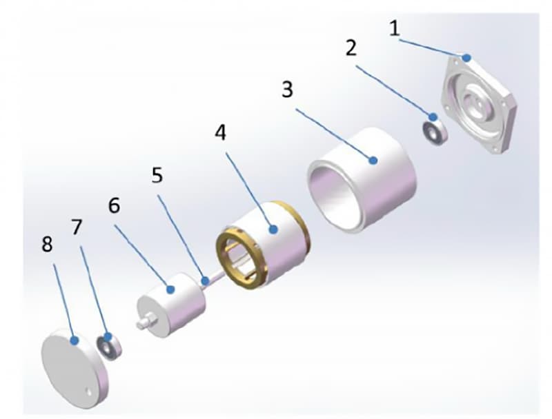
Depending on the power of the motor, a choice is made between water cooling or air cooling methods. (Figure 1)
Figure 1 Structural schematic diagram of AC asynchronous motor
1- Front End Cover 2- Front Bearing 3- Motor Housing 4- Squirrel Cage Rotor 5- Motor Shaft 6- Stator 7- Rear Bearing 8- Rear End Cover 9- Position Sensor 10- Sensor Maintenance Cover
2. Working Principle of AC Asynchronous Motor
(1) Working Principle of AC Asynchronous Motor Drive
1) The stator provides a rotating magnetic field. To provide torque, the AC asynchronous motor needs to pass three-phase AC power through the stator coil, creating a continuously rotating magnetic field (with a magnetic field rotation speed of ns).
The AC asynchronous motor requires that the three-phase windings of the stator must be symmetrical, and the stator iron core must be spaced 120 electrical degrees apart. The current passing through the three-phase symmetrical winding must also be symmetrical, with the same size, frequency, and phase difference of 120 degrees. The rotation speed of the rotating magnetic field is given by the equation (1).
ns=60f/p (1)
In this equation, ns is the rotation speed of the rotating magnetic field (also known as synchronous speed), r/min; f is the frequency of the three-phase AC power, Hz; p is the number of pole pairs.
For a drive motor that has been designed and put into production, the number of pole pairs is fixed, so the factor determining the speed of the magnetic field rotation is the frequency of the three-phase AC power. As the power grid frequency in our country is f=50Hz, there is a linear relationship between the motor speed and the number of pole pairs. (Figure 2)
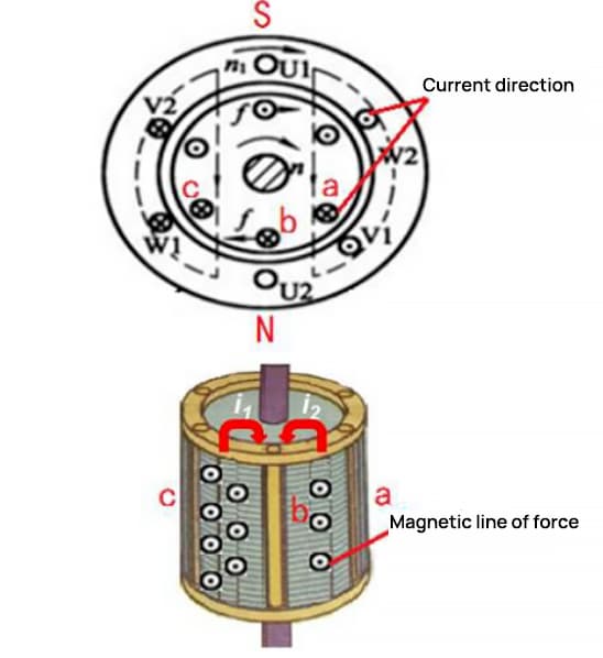
Figure 2 Rotating Magnetic Field Diagram of Two Pole Stator Windings
2) The squirrel cage rotor provides induced eddy currents. As the stator provides a rotating magnetic field, an eddy current is induced on the squirrel cage rotor conductor, as shown in Figure 3.
Figure 3 Eddy Current in Cage Rotor Windings
In the magnetic area between conductors c and b of the squirrel cage winding, there are outward magnetic lines of force, and these magnetic lines of force are enhanced under the action of the rotating magnetic field.
Therefore, an i1 eddy current will be induced on conductors c, b; similarly, weakening magnetic lines of force in the area between conductor a and conductor b will induce an i2 eddy current on the conductor.
The current on conductor b, under the action of the stator’s rotating magnetic field, will cause the squirrel cage winding conductor b to be subject to electromagnetic force, thereby causing the rotor to generate an electromagnetic torque and start to rotate. The rotating rotor gradually catches up with the rotating magnetic field, rotating at a speed n slightly slower than the “synchronous speed ns” of the magnetic field.
This phenomenon, where the rotor’s rotation speed n is slightly slower than the stator’s magnetic field speed ns, is called rotor slip. This asynchronous slip allows the squirrel cage rotor conductor to continuously cut the magnetic lines of force, producing induced eddy currents.
Consequently, on the rotor, electrical energy is converted into mechanical energy, ensuring continuous external output.
(2) The Principle of Power Generation in AC Asynchronous Motors
According to Faraday’s Law of Electromagnetic Induction, when a section of the closed circuit conductor cuts through the magnetic field lines in motion, an induced current is generated within the conductor, with the generated electromotive force known as the induced electromotive force.
In an AC asynchronous motor, when the motor is used as a generator, the stator is energized with a three-phase current to provide the magnetic field, and the rotor winding provides the conductor.
When external mechanical force, such as the drive shaft of a car, drives the rotor shaft, thus making the rotor move, if the rotor’s speed is higher than the synchronous speed of the stator’s rotating magnetic field, the AC asynchronous motor then acts as a generator.
The direction of the rotor cutting the rotating magnetic field is opposite to when it works as a drive motor, thus the direction of the rotor’s induced electromotive force is also reversed.
During the power generation process, the motor’s rotor experiences an electromagnetic torque that is opposite to the external dragging force, causing the rotor speed to decrease.
3. Advantages, Disadvantages, and Applications of AC Asynchronous Motors
AC asynchronous motors excel in providing adjustable output torque over a wide range, capable of forcibly increasing output torque over short periods during acceleration or climbing. Electric vehicles driven by permanent magnet synchronous motors often employ additional gearbox mechanisms to augment torque for speed enhancement.
However, AC asynchronous motors present several drawbacks. Due to unilateral excitation, they require larger starting currents and more current per unit of torque produced. The stator houses reactive excitation currents, resulting in higher energy consumption than permanent magnet synchronous motors, with a lagging power factor.
Overload conditions frequently occur during heavy-duty drives. Their relatively complex structure demands high control technology expertise, making them more expensive to manufacture, and they have comparatively lower power density.
Currently, AC asynchronous motors are commonly used as drive motors in electric vehicles developed in the United States.
II. Permanent Magnet Synchronous Motor
1. Structure of Permanent Magnet Synchronous Motor
The structure of a Permanent Magnet Synchronous Motor comprises a stator, rotor, motor shaft, front and rear bearings, end cap, cooling water channel, position sensor, temperature sensor, low voltage harness, and power harness.
The stator is formed by the stator iron core and three-phase windings; the rotor consists of permanent magnet poles and an iron core, with the iron core made of stacked silicon steel sheets.
The arrangement of the permanent magnets in the rotor primarily includes surface-mounted, surface-embedded, and interior permanent magnet rotors, with interior permanent magnet rotors commonly used in new energy motors. (Figure 4)
Figure 4 Schematic diagram of permanent magnet synchronous motor structure
1- Front End Cover 2- Front End Bearing 3- Motor Housing 4- Stator 5- Motor Shaft 6- Integrated Permanent Magnet Rotor 7- Rear End Bearing 8- Rear End Cover (Incorporated Position Sensor)
2. Working Principle of Permanent Magnet Synchronous Motor
(1) Driving Principle of Permanent Magnet Synchronous Motor
The rotating magnetic field is provided by the stator, produced in the same way and at the same speed as an AC asynchronous motor. The magnetic poles are supplied by the rotor’s permanent magnets.
Thus, the rotating magnetic field generated by the stator forms a circuit with the rotor’s permanent magnet poles and iron core. Following the principle of minimum magnetic reluctance, i.e., the magnetic flux always closes along the path of least magnetic resistance, the rotor is drawn into rotation by the electromagnetic force of the rotating field.
Consequently, the permanent magnet rotor synchronously rotates with the rotating magnetic field generated by the stator, thereby driving the rotation of the motor shaft.
(2) Power Generation Principle of Permanent Magnet Synchronous Motor
Following Faraday’s law of electromagnetic induction, a portion of the closed circuit’s conductor is supplied by the three-phase stator windings, with the magnetic field provided by the permanent magnets on the rotor.
When external torque drives the rotor to rotate, it generates a rotating magnetic field, cutting through part of the conductors in the three-phase stator windings and inducing a symmetrical three-phase current.
At this point, the rotor’s kinetic energy is converted into electrical energy, and the Permanent Magnet Synchronous Motor works as a generator.
3. Advantages, Disadvantages, and Application Scope of Permanent Magnet Synchronous Motor
The advantages of a Permanent Magnet Synchronous Motor include its small size, light weight, high power density, lower energy consumption, lower temperature rise, and higher efficiency compared to asynchronous motors.
It can be designed as a high-starting torque, high-overload-capacity structured motor based on requirements.
The Permanent Magnet Synchronous Motor strictly synchronizes and has good dynamic response performance, suitable for frequency control; the motor’s torque and speed can be adjusted over a wide range by altering current and frequency.
However, the permanent magnet material used in Permanent Magnet Synchronous Motors is usually neodymium iron boron strong magnetic material, which is relatively brittle and may fracture under intense vibration.
Furthermore, the use of permanent magnet material in the rotor can lead to magnetic decay in the motor’s operation and overheating situations, resulting in a power decrease.
Currently, Permanent Magnet Synchronous Motors are widely used in new energy vehicle motors, with the new energy markets in Asia and Europe mainly utilizing Permanent Magnet Synchronous Motors as new energy motors.
III. Switched Reluctance Motor
1. Structure of the Switched Reluctance Motor
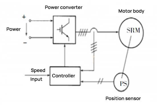
The Switched Reluctance Motor (SRM) is a typical mechatronic motor, also known as the “Switched Reluctance Drive System.” The motor primarily includes four components: the SRM itself, a power converter, rotor position sensors, and a controller, as shown in Figure 5.
Figure 5 System Block Diagram of Switched Reluctance Motor
The main structure of the SRM includes the stator, rotor, position sensors, front and rear bearings, front and rear end caps, and the motor casing, as depicted in Figure 6. The stator comprises the stator core and the windings.
Figure 6 Structure of Switched Reluctance Motor
1- Front End Cover 2- Front End Bearing 3- Rotor 4- Motor Shaft 5- Stator 6- Motor Housing 7- Rear End Bearing 8- Rear End Cover 9- Position Sensor 10- Sensor Maintenance Cover 11- Cooling Fan 12- Fan End Cover
Both the stator core and the rotor utilize salient-pole structures, and are made up of laminated silicon steel sheets. The stator salient poles are equipped with windings, while the rotor has no windings or permanent magnets.
The three-phase 6/4 pole structure indicates that the motor’s stator has six salient poles, and the rotor has four salient poles. The concentrated windings on two symmetrical salient poles of the stator are wired in series to form a phase, and the number of phases equals the number of stator salient poles divided by two, as shown in Figure 7(a).
Figure 7 Salient Pole and Winding Structure of Switched Reluctance Motor
The three-phase 12/8 pole structure indicates that the stator of the motor has twelve salient poles, and the rotor has eight salient poles. The windings on four symmetric salient poles of the stator are wired in series to form a phase, and the number of phases equals the number of stator salient poles divided by four, as shown in Figure 7(b).
The more phases a switched reluctance motor has, the smaller the stepping angle, the smoother the operation, and the more favorable it is to reduce torque ripple. However, the control becomes more complex, leading to an increase in the number of main switching devices and costs.
The calculation for the stepping angle is shown in equation (2):
α = 360° × (Number of Stator Poles – Number of Rotor Poles) / (Number of Stator Poles)
For example, for a three-phase 6/4 pole motor, the stepping angle α = 360° × 2/(6×4) = 30°.
2. Working Principle of the Switched Reluctance Motor
(1) Drive Operation Principle of the Switched Reluctance Motor
As shown in the working principle diagram of the three-phase 12/8 pole SRM in Figure 8, when the current of the A-phase winding controls the main switch S1, S2 to close, the A-phase is energized and magnetized.
Figure 8 Working Principle of Switched Reluctance Motor
The magnetic field force generated within the motor forms a radial magnetic field with OA as the axis. The magnetic force lines of this field are bent where they pass through the air gap between the stator salient poles and the rotor salient poles.
At this time, the magnetic reluctance of the magnetic circuit is greater than when the stator salient pole and the rotor salient pole coincide. Therefore, the rotor salient pole is acted upon by the magnetic pull, which aligns the rotor pole axis Oa with the stator pole axis OA.
This generates an electromagnetic torque of magnetic reluctance property, causing the rotor to begin rotating counterclockwise. When the A-phase current is turned off and the B-phase power source is established, the magnetic field within the motor rotates 30 degrees.
The rotor then rotates an additional 15 degrees counterclockwise under the action of the electromagnetic pull. If power is sequentially supplied to the A-B-C-A phase windings, the rotor will continuously rotate counterclockwise.
When the stator windings in each phase are energized in turn, the stator magnetic field rotates 3×30 degrees, and the rotor rotates a rotor pole pitch of 3×15 degrees (i.e., 360 degrees / number of rotor salient poles).
If power is sequentially supplied to the A-C-B-A phase windings, the rotor will rotate clockwise. The direction of rotation of the switched reluctance motor is not related to the direction of the current but is determined by the power-on sequence of the stator phase windings.
In the actual operation of multi-phase motors, it is also common for two or more phase windings to be energized simultaneously.
(2) Operating Principle of a Switched Reluctance Generator
The working state of a switched reluctance generator involves three conditions: the excitation state, the continuation state, and the power generation state, as demonstrated by the waveform of the phase inductance L in Figure 10.
Figure 9 Schematic diagram of the working state of a switched reluctance motor
Figure 10 Changes in phase inductance with rotor position
In Figure 9, the angle θ is defined as the angle between the rotor tooth pole axis and the stator tooth slot axis. When the rotor tooth pole axis aligns with the corresponding stator tooth slot axis, the phase inductance is at its minimum (defined as θ=0°). The winding phase inductance remains constant at Lmin until the leading edge of the rotor pole meets the trailing edge of the stator pole (θ=θ1).
As the rotor continues to rotate and the rotor pole starts to overlap with the stator pole, up until the trailing edge of the rotor pole and the trailing edge of the stator pole fully align (at this time, θ=θ2), the winding phase inductance linearly increases within this region, reaching a maximum of Lmax.
When the rotor continues to rotate such that the leading edge of the rotor pole aligns with the leading edge of the stator pole (at this time, θ=θ4), the phase inductance remains at Lmax.
According to the basic theory of the electromagnetic field, the existence of a magnetic field is accompanied by the electromagnetic torque of the motor rotor, which can be represented by equation (3).
If the windings of the switched reluctance motor are switched on and off between θ3 and θ4, the motor operates as a generator. At this time, a current forms in the declining inductance region, thus dL/dθ<0.
If current passes through the phase windings at this time, a braking torque (T(θ, i)<0) is generated. If an external mechanical force maintains the rotation of the motor, the motor absorbs mechanical energy and converts it into electrical output, indicating that the switched reluctance motor is operating in generator mode.
3. Advantages, Disadvantages and Application Scope of Switched Reluctance Motors
The advantages of switched reluctance motors are their simple and reliable structure, good start-up performance, high efficiency, and low cost. They offer a wide range of speed control capabilities by varying the conduction, shut-off angles, and voltage. However, the drawbacks include substantial torque ripple and high noise.
Currently, they are used in some small electrically driven vehicles, such as electric four-wheel mobility scooters and patrol cars.
IV. Conclusion
Given the distinct performance characteristics required by the propulsion motors of new energy vehicles, the type of drive motor selected varies across different models in the market.
This article outlines the structure and working principles of commonly used new energy drive motors such as AC asynchronous motors, permanent magnet synchronous motors, and switched reluctance motors. This information will aid in a better understanding of these drive motors.
Furthermore, the structure and principles of each motor type differ, leading to a wide range of applications. As per national industrial strategic planning, research focusing on the electric drive systems of environmentally-friendly new energy vehicles will continue to expand. Consequently, the variety and technological level of motors will also keep advancing.
As the founder of MachineMFG, I have dedicated over a decade of my career to the metalworking industry. My extensive experience has allowed me to become an expert in the fields of sheet metal fabrication, machining, mechanical engineering, and machine tools for metals. I am constantly thinking, reading, and writing about these subjects, constantly striving to stay at the forefront of my field. Let my knowledge and expertise be an asset to your business.
Ever wondered how trains can float above tracks or how robots achieve precise movements? This article unveils the fascinating world of linear motors, explaining their principles, types, and unique advantages.…
Servo systems are an integral part of electromechanical products, providing the highest level of dynamic response and torque density. Hence, the trend in drive system development is to replace traditional…
Have you ever wondered what sets DC motors apart from AC motors? In this article, we explore the fundamental differences between these two types of motors, including their operating principles,…
Have you ever wondered what keeps the world spinning smoothly? The unsung heroes behind the scenes are bearings. These small but mighty components play a crucial role in reducing friction…
Have you ever wondered what powers the machines that drive our world? Gearboxes are the unsung heroes behind many industries, from automotive to wind energy. In this article, you'll explore…
Choosing the right servo motor for your project can be a daunting task with so many options available. This article simplifies the process by breaking down the key considerations: application…
How do electric motors convert electricity into motion? Imagine a world where nearly half of our power drives these motors. This article dives into the science behind electric motors, explaining…
Imagine the world without the hum of motors—no cars, no appliances, no industrial machines. Motors convert electrical energy into mechanical energy, powering everything from toys to manufacturing giants. In this…