How Do Electric Motors Work? A Comprehensive Guide
How do electric motors convert electricity into motion? Imagine a world where nearly half of our power drives these motors. This article dives into the science behind electric motors, explaining how they use magnetic fields and current to produce rotational or linear motion. By understanding the different types, such as DC and AC motors, and their internal mechanisms, you’ll gain insight into their crucial role in modern technology. Ready to unravel the mysteries of these ubiquitous devices? Keep reading to explore the principles and applications of electric motors.
Nearly half of the world’s power consumption is attributed to electric motors, thus improving their efficiency is considered the most effective measure in addressing global energy issues.
Types of Motors
Generally, motors convert the force generated by the flow of current in a magnetic field into rotational motion, but broadly, this also includes linear motion.
Based on the type of power source driving the motor, they can be classified into DC and AC motors.
Furthermore, according to the principle of motor rotation, they can be roughly divided into the following categories, excluding special motors.
1. DC (Direct Current) Motors
(1) Brushed Motors
The widely used brushed motors are generally referred to as DC motors. They rotate by sequentially contacting the electrodes called “brushes” (on the stator side) and the “commutator” (on the armature side) to switch the current.
(2) Brushless DC Motors
Brushless DC motors do not require brushes and commutators. They use switching functions such as transistors to switch the current and achieve rotational motion.
(3) Stepper Motors
This motor operates in synchronization with pulse power and is therefore also known as a pulse motor. Its characteristic is the ability to easily achieve accurate positioning operation.
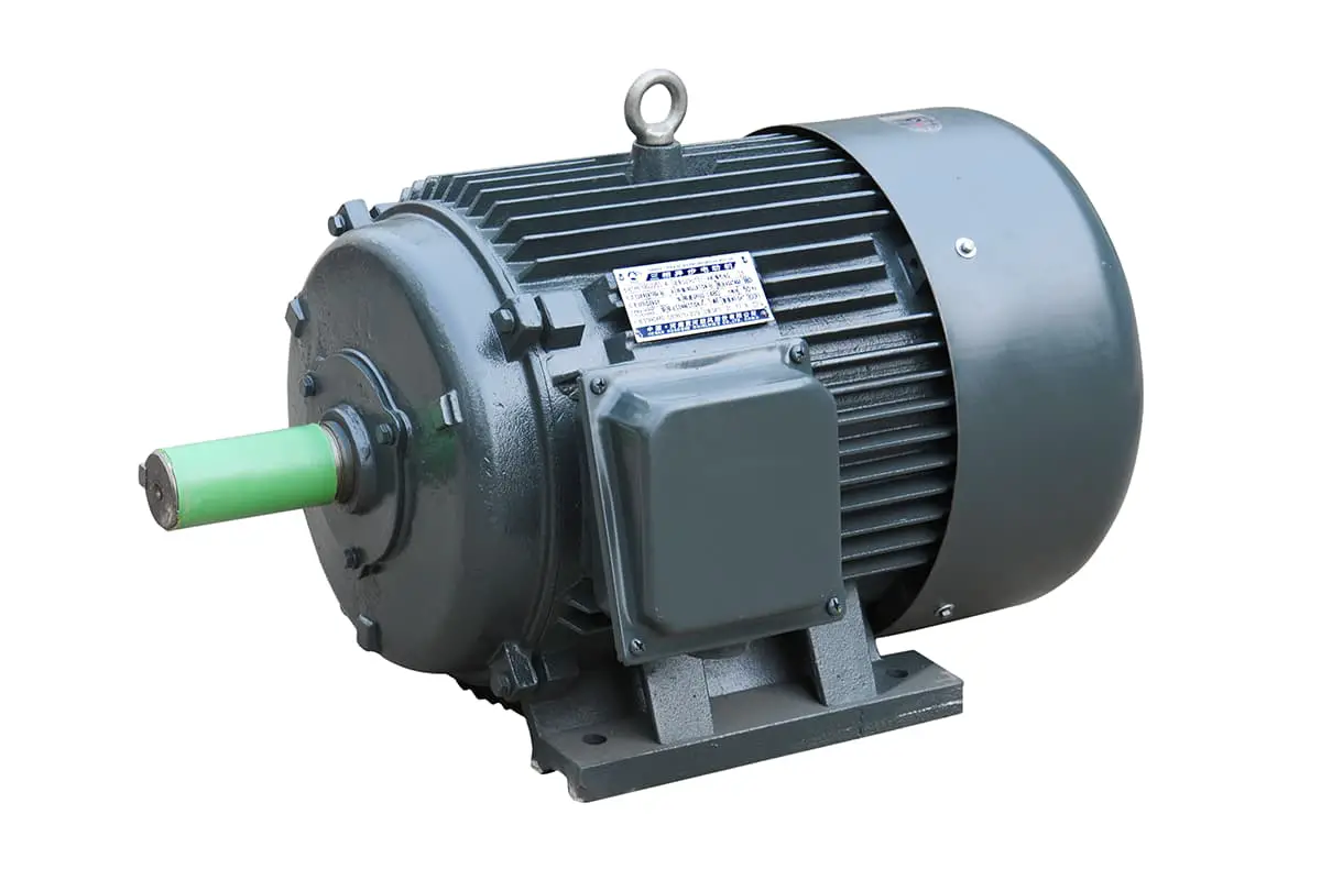
2. AC (Alternating Current) Motors
(1) Asynchronous Motors
AC current generates a rotating magnetic field in the stator, causing the rotor to induce current and rotate under its interaction.
(2) Synchronous Motors
AC current creates a rotating magnetic field, and the rotor with magnetic poles rotates due to attraction. The rotation speed is synchronized with the power frequency.
Stepper Motor
Brushed Direct Current Motor
Brushless Direct Current Motor
Current, Magnetic Fields, and Force
Firstly, to facilitate subsequent explanations on motor principles, let’s revisit the basic laws/rules concerning current, magnetic fields, and force.
Though it may evoke a sense of nostalgia, this knowledge can be easily forgotten if magnetic components are not regularly used.
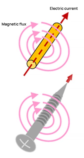
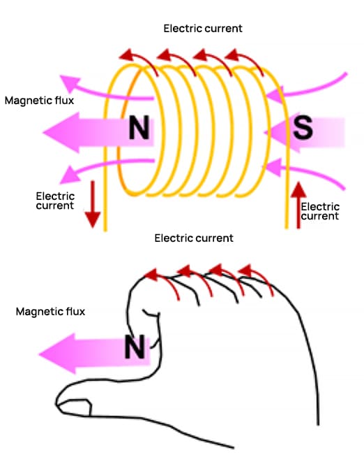
Ampere’s Law (Right Hand Screw Rule)
The magnetic flux generated by a current in a coil
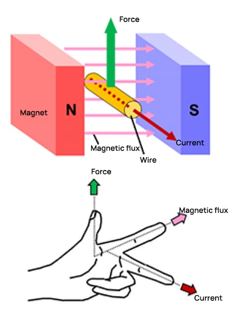
Based on Fleming’s Left Hand Rule
We’ll illustrate this using images and equations.
Schematic diagram of motor rotation
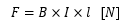
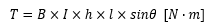
When the wire frame is rectangular, the force acting on the current must be considered. The force F exerted on parts a and c of the frame is:
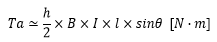
Torque is generated around the central axis. For instance, when considering a state where the rotation angle is only θ, the force acting at right angles to b and d is sinθ. Consequently, the torque Ta in part a is represented by the following formula:
Considering part C in the same manner, the torque is doubled, generating a torque calculated by the following formula:
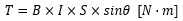
Given that the area of a rectangle is S = h*l, the following result can be derived by substitifying it into the previously mentioned formula:
This formula is not only applicable to rectangles, but also to other common shapes such as circles. This principle underlies the operation of electric motors.
How Does a Motor Rotate?
1) Motors rotate by utilizing magnets and magnetic force.
Around a permanent magnet with a rotating shaft:
① Rotate the magnet (to generate a rotating magnetic field).
② This follows the principle that opposite poles (N and S) attract, while like poles repel.
③ The magnet with the rotating shaft will then rotate.
This is the basic principle of motor rotation.
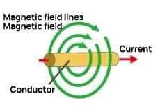
The current flowing through the conductor generates a rotating magnetic field around it, causing the magnet to spin, which essentially represents the same state of motion.
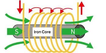
Furthermore, when a conductor is wound into a coil, the magnetic forces synthesize to form a large magnetic flux, creating a North and South pole.
Additionally, by inserting a ferrous core into the coiled conductor, the magnetic field lines can pass through more easily, thereby generating a stronger magnetic force.
2) Operational Rotating Motors
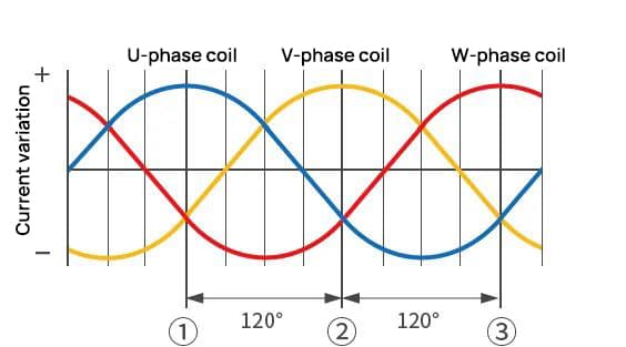
In this context, we present a practical approach for rotating motors, demonstrating the usage of three-phase alternating current and coils to generate a rotating magnetic field. (Three-phase alternating current refers to alternating signals phased at intervals of 120°.)
The synthesized magnetic field in the aforementioned State ① corresponds to Figure ① below.
The synthesized magnetic field in the previously mentioned State ② aligns with Figure ② shown below.
The synthesized magnetic field associated with the above-noted State ③ is depicted in Figure ③ below.
As stated above, the coil wound around the iron core is divided into three phases: U-phase coil, V-phase coil, and W-phase coil, arranged at 120° intervals. The coil with a higher voltage generates a north pole, while the one with a lower voltage generates a south pole.
Each phase varies according to the sine wave, therefore, the polarity (north or south pole) and the magnetic field (magnetic force) generated by each coil will change.
At this point, if we only consider the coil generating the north pole, the sequence of changes goes from U-phase coil to V-phase coil, then to W-phase coil, and finally back to U-phase coil, thus producing a rotation.
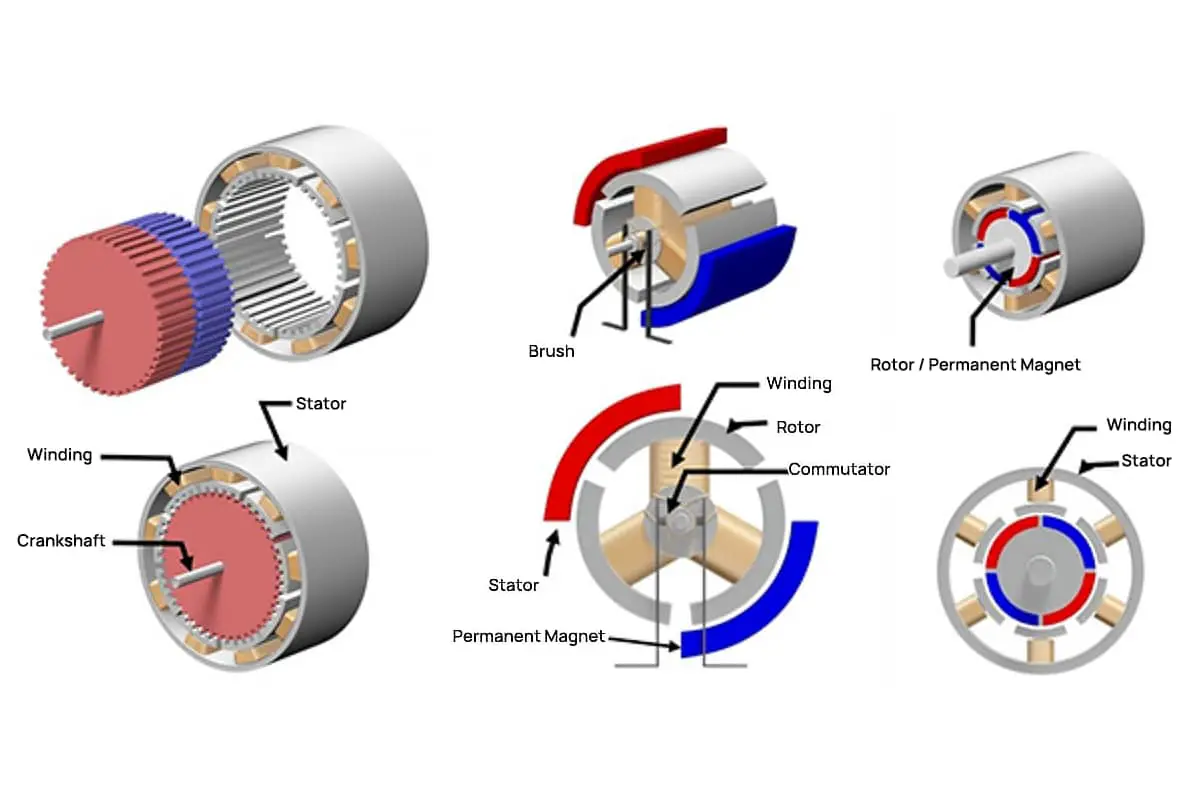
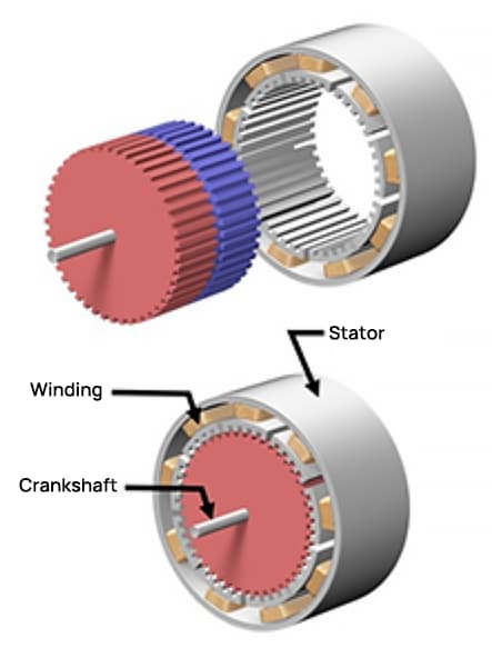
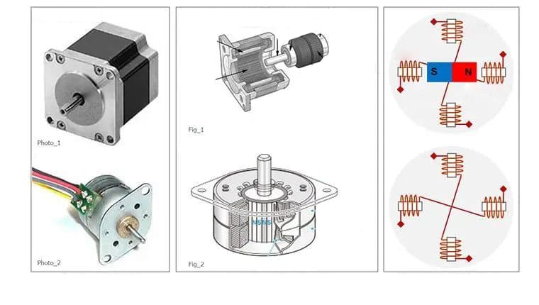
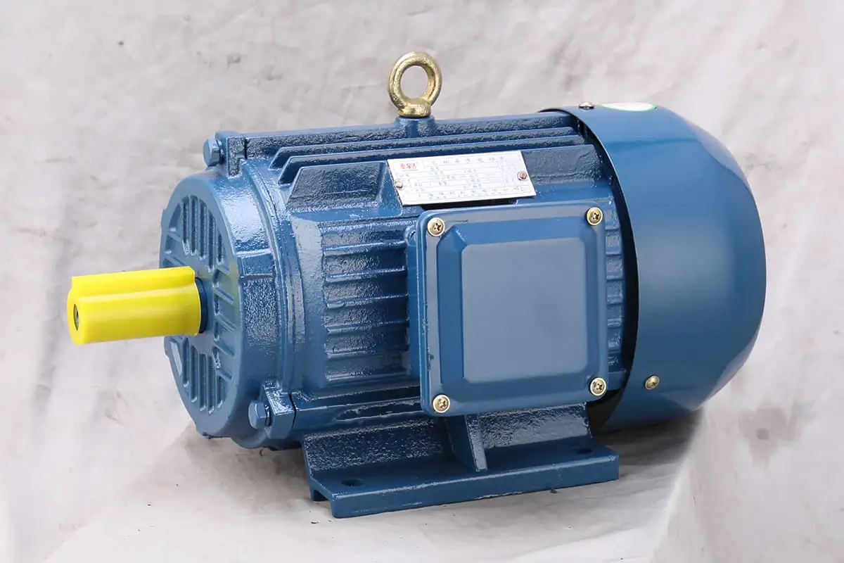
Structure of Small Motors
The figure below provides a general construction and comparison of three types of motors: stepper motors, brushed direct current (DC) motors, and brushless direct current (DC) motors.
The basic components of these motors mainly include coils, magnets, and rotors. Due to their diverse types, they are further classified into coil-fixed and magnet-fixed types.
Stepper Motor
Brushed Direct Current Motor
Brushless Direct Current Motor
The following is a structural description related to the example diagram. Please understand that this document introduces the structure within a broad framework, as there may be other structures if divided in more detail.
The coils of the stepper motor here are fixed on the outside, with the magnets rotating on the inside; the magnets of the brushed DC motor are fixed on the outside, with the coils rotating on the inside.
The supply of power to the coils and the change in the direction of the current are handled by brushes and commutators; in brushless motors, the coils are fixed on the outside, with the magnets rotating on the inside.
Due to variations in motor types, even with the same basic components, their structures can differ. Specific details will be explained in each section.
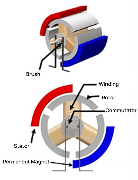
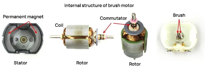
Brushed Motor
Structure of Brushed Motor
The image below shows the exterior of a brushed DC motor commonly used in models, as well as an exploded view of a typical two-pole (two magnets) and three-slot (three coils) motor. Many may have experience disassembling motors and removing magnets.
In a brushed DC motor, the permanent magnets are stationary while the coils can rotate around the internal center. The stationary side is known as the “stator,” and the rotating side is referred to as the “rotor.”
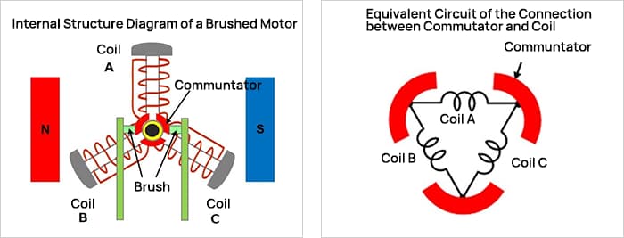
Here is a schematic diagram illustrating structural concepts.
The central axis of rotation is surrounded by three commutators – curved metal plates used for electrical current switching. To prevent contact with one another, the commutators are arranged 120° apart (360° ÷ 3 units). These commutators rotate with the axis.
Each commutator is connected to one end of a coil and another, and together, the three commutators and three coils form a complete circuit network (ring).
Two brushes are fixed at 0° and 180° to make contact with the commutators. An external DC power source is connected to the brushes, and the current flows along the path from brush to commutator, from commutator to coil, and from coil back to the brush.
This is the principle of rotation for a brushed motor.
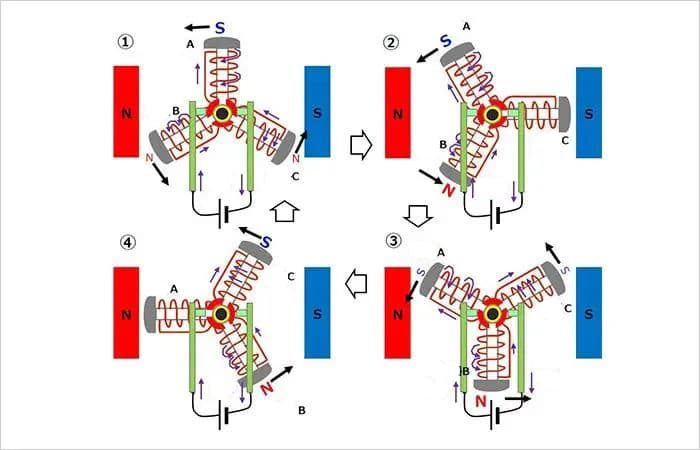
① Counter-clockwise rotation from the initial state
Coil A is at the top, with the power source connected to the brushes, designating the left side as (+) and the right as (-). A high current flows from the left brush through the commutator into coil A. This turns the upper (outer) part of coil A into a south pole (S).
Since half of coil A’s current flows from the left brush to coils B and C in the opposite direction to coil A, the outer sides of coils B and C become weak north poles (N), indicated by smaller letters in the diagram.
The magnetic fields generated in these coils, along with the repulsion and attraction of the magnets, provide a force that rotates the coils counter-clockly.
② Further counter-clockwise rotation
Next, assuming that coil A has rotated 30° counter-clockwise, the right brush contacts the two commutators.
The current in coil A continues to flow from the left brush across the right brush, and the outer side of the coil remains a south pole. The same current flows through coil B, turning its outer side into a stronger north pole. Coil C is short-circuited by the brushes at both ends, so there is no current flow and no magnetic field is generated.
Even in this state, a counter-clockly rotating force is applied. From ③ to ④, the upper coil continues to be driven leftward, and the lower coil continues to be driven rightward, resulting in continued counter-clockwise rotation.
Every 30° rotation of the coil to states ③ and ④, when the coil is above the central horizontal axis, its outer side becomes a south pole; when it’s below, it becomes a north pole, and this motion repeats.
In other words, the upper coil repeatedly experiences a leftward force, and the lower coil a rightward force (both in the counter-clockwise direction). This keeps the rotor rotating counter-clockwise.
If the power source is connected to the opposite left brush (-) and right brush (+), a reverse magnetic field is generated in the coil, thus reversing the direction of the force applied to the coil, making it rotate clockwise.
Additionally, when the power source is disconnected, the rotor of the brushed motor stops rotating due to the absence of the magnetic field that was driving its rotation.
Three-Phase Full-Wave Brushless Motor
Appearance and Structure of the Three-Phase Full-Wave Brushless Motor
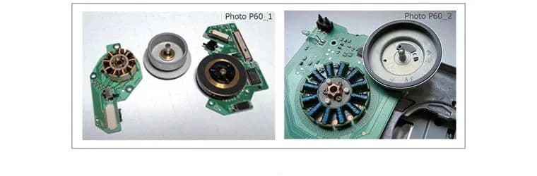
The image below depicts an example of the appearance and structure of the brushless motor.
Example of Brushless Motor Appearance and Structure
The left side shows an example of the main spindle motor used to rotate the disc in the disc playback device, containing a total of nine coils, three phases times three.
On the right is an example of the main spindle motor of an FDD device, with twelve coils (three phases times four). The coils are mounted on a circuit board and wrapped around an iron core.
On the right side of the coil, the disc-shaped component is a permanent magnet rotor. The perimeter is a permanent magnet, the rotor’s shaft is inserted into the center of the coil and covers part of the coil, with the permanent magnet surrounding the periphery of the coil.
Internal Structure Diagram and Equivalent Circuit of Three-Phase Full-Wave Brushless Motor
Next are the simplified internal structure diagram and the equivalent circuit diagram of the coil connections for a three-phase full-wave brushless motor.
This schematic represents a simple structure of a 2-pole (2 magnets) 3-slot (3 coils) motor. It resembles the structure of a brushed motor with an equal number of poles and slots, except the coil side is stationary and the magnets are rotatable. Naturally, this design does not incorporate brushes.
In this configuration, the coils are connected in a Y-formation. Semiconductor components supply current to the coils, controlling the inflow and outflow of current based on the position of the rotating magnets.
In this example, a Hall element is used to detect the position of the magnets. The Hall element is placed between the coils, where it detects the voltage generated by magnetic field strength and uses it for positional information.
In the previously provided image of the FDD spindle motor, a Hall element (located above the coils) can also be observed, serving to detect position between the coils.
The Hall element is a well-known magnetic sensor. It can convert the magnitude of a magnetic field into a voltage, representing the direction of the field with positive or negative values. Below is a diagram illustrating the Hall effect.
The Hall element utilizes the phenomenon that “when the current IH flows through the semiconductor and the magnetic flux B passes through at a right angle to the current, a voltage VH is generated in the direction perpendicular to the current and the magnetic field.”
This phenomenon, known as the “Hall Effect,” was discovered by American physicist Edwin Herbert Hall. The voltage VH generated is represented by the following formula.
VH=(KH/d)・IH・B
Where KH is the Hall coefficient, and d is the thickness of the flux-penetrating surface.
As the formula suggests, the larger the current, the higher the voltage. This characteristic is often used to detect the position of the rotor (magnet).
Rotation Principle of Three-Phase Full-Wave Brushless Motor
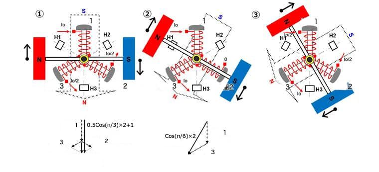
The rotation principle of the brushless motor will be explained in steps ① to ⑥. For ease of understanding, the permanent magnet has been simplified from a circle to a rectangle.
1) In a three-phase coil system, imagine coil 1 fixed at the 12 o’clock position of a clock, coil 2 at 4 o’clock, and coil 3 at 8 o’clock. Assume a 2-pole permanent magnet with its North pole on the left and South pole on the right, capable of rotation.
Current Io is introduced into coil 1, generating a South pole magnetic field on the outside of the coil. Half of this current, Io/2, flows out from coils 2 and 3, creating a North pole magnetic field on their exterior.
When the magnetic fields of coils 2 and 3 undergo vector synthesis, a downward North pole magnetic field is generated. This field is half the size of the magnetic field produced when current Io passes through one coil and, when added to the field of coil 1, becomes 1.5 times larger. This creates a synthesized magnetic field at a 90° angle to the permanent magnet, thus generating maximum torque and prompting clockwise rotation of the permanent magnet.
As the current in coil 2 decreases and that in coil 3 increases based on the rotation position, the synthesized magnetic field also rotates clockwise, continuing the rotation of the permanent magnet.
2) With a 30° rotation, current Io enters coil 1, setting the current in coil 2 to zero, and making current Io flow out of coil 3.
The exterior of coil 1 becomes the S pole, and the exterior of coil 3 turns into the N pole. During the vector combination, the generated magnetic field is √3 (approximately 1.72) times that of a single coil carrying current Io. This also results in a composite magnetic field at a 90° angle to the permanent magnet’s field, rotating clockwise.
When the inflow current Io in coil 1 is reduced according to the rotational position, the inflow current in coil 2 starts to increase from zero, and the outflow current in coil 3 increases to Io, the composite magnetic field also rotates clockwise, and the permanent magnet continues to rotate.
Assuming all phase currents are sinusoidal, the current here is Io×sin(π⁄3)=Io×√3⁄2. Through the vector combination of the magnetic field, the total magnetic field size is 1.5 times the field produced by a single coil ((√3⁄2)2×2=1.5). When all phase currents are sinusoidal, regardless of the position of the permanent magnet, the size of the vector composite magnetic field is always 1.5 times that of a single coil, and the magnetic field forms a 90° angle with the magnetic field of the permanent magnet.
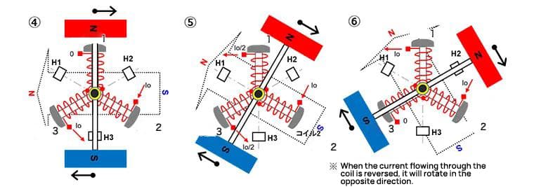
3) Upon further rotation of 30°, current Io/2 flows into coil 1, current Io/2 enters coil 2, and current Io flows out of coil 3.
The exterior of coil 1 becomes the S pole, the exterior of coil 2 also turns into the S pole, and the exterior of coil 3 becomes the N pole. During vector combination, the generated magnetic field is 1.5 times the magnetic field produced when current Io passes through a single coil (same as in ①). A composite magnetic field is also formed here at a 90° angle to the permanent magnet’s field, rotating clockwise.
Steps 4 through 6, rotate in the same manner as steps 1 through 3.
In this way, by sequentially switching the current flowing into the coil according to the position of the permanent magnet, the permanent magnet will rotate in a fixed direction. Similarly, if the current is reversed and the direction of the synthetic magnetic field is reversed, it will rotate counterclockwise.
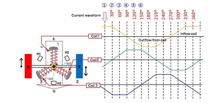
The diagram below continuously displays the current for each coil in each of the aforementioned steps 1 through 6. From the above introduction, the relationship between the changes in current and rotation should be understood.
Stepper Motor
The stepper motor is a type of motor that can accurately synchronize with pulse signals to control rotation angles and speed. It is also known as a “pulse motor”.
The stepper motor, which doesn’t require a position sensor and can accomplish accurate positioning via open-loop control, is widely used in equipment that requires precise location.
Structure of a Stepper Motor (Two-Phase Bipolar)
The images below, from left to right, display an example of the external appearance of a stepper motor, a simple diagram of its internal structure, and a conceptual schematic of its design.
The exterior examples provided are of HB (Hybrid) and PM (Permanent Magnet) type stepper motors. The middle diagrams also depict the structures of HB and PM types.
Stepper motors are structured with fixed coils and a rotating magnet. The right-side conceptual diagram of the internal structure of the stepper motor illustrates an example of a PM motor using two phases (two sets) of coils. In the basic structure examples of the stepper motors, the coils are positioned externally, and the permanent magnet is internally located. Beyond two-phase, there are also types with a higher number of phases such as three-phase and five-phase.
Some stepper motors have distinct structures, but for the sake of explaining their working principles, this article provides the basic structure of stepper motors. Through this article, it is intended to understand that stepper motors primarily adopt a structure with fixed coils and a rotating permanent magnet.
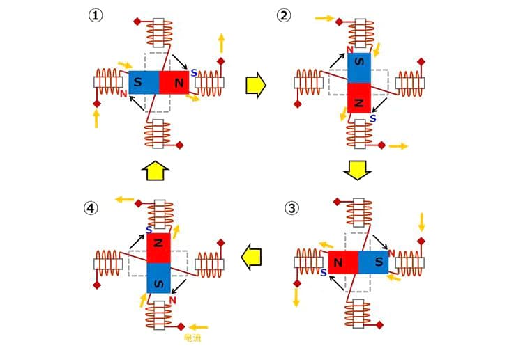
Basic Working Principle of Stepper Motors (Single-Phase Excitation)
The following diagram is used to explain the basic working principle of stepper motors. This is a single-phase (one set of coils) excitation example of the above-mentioned two-phase bipolar coils. The premise of the diagram is the state changing from ① to ④. The coils consist of Coil 1 and Coil 2. Additionally, the arrow of the current represents the direction of current flow.
①Direct the current to flow in from the left side of coil 1 and out from the right side. Avoid any current flow through coil 2. As a result, the inner side of the left coil 1 becomes N (north), while the inner side of the right coil 1 becomes S (south). Consequently, the permanent magnet in the middle is attracted by the magnetic field of coil 1, adopting a state with S on the left and N on the right, and halts.
②Next, halt the current in coil 1, directing it to flow in from the top of coil 2 and out from the bottom. The inner side of the top coil 2 then becomes N, and the inner side of the bottom coil 2 becomes S. The permanent magnet is attracted by this magnetic field, rotating 90 degrees clockwise and stopping.
③Thereafter, stop the current in coil 2, directing it to flow in from the right side of coil 1 and out from the left side. The inner side of the left coil 1 becomes S, and the right coil 1’s inner side becomes N. The permanent magnet is again attracted by this field, rotating another 90 degrees clockwise and stopping.
④Finally, halt the current in coil 1, directing it to flow in from the bottom of coil 2 and out from the top. The inner side of the top coil 2 becomes S, while the inner side of the bottom coil 2 becomes N. Once more, the permanent magnet is attracted by this magnetic field, rotating 90 degrees clockwise and stopping.
By switching the current flow through the coils in the above sequence (① to ④) via an electronic circuit, the stepper motor can be made to rotate. In this example, each switch action rotates the stepper motor by 90 degrees.
Moreover, maintaining a continuous current flow through a specific coil allows the motor to remain in the halted state while maintaining torque. As a side note, reversing the order of the current flow through the coils can cause the stepper motor to rotate in the opposite direction.
As the founder of MachineMFG, I have dedicated over a decade of my career to the metalworking industry. My extensive experience has allowed me to become an expert in the fields of sheet metal fabrication, machining, mechanical engineering, and machine tools for metals. I am constantly thinking, reading, and writing about these subjects, constantly striving to stay at the forefront of my field. Let my knowledge and expertise be an asset to your business.
Have you ever wondered what keeps an electric motor running smoothly without overheating? Understanding the safe operating temperatures for motors is crucial for their longevity and performance. In this article,…
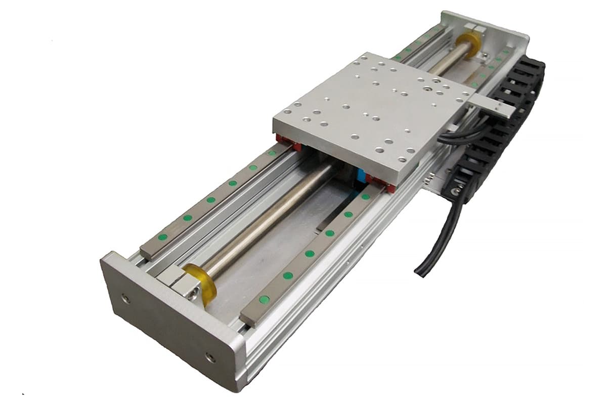
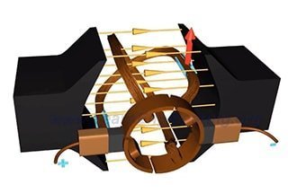
Ever wondered how trains can float above tracks or how robots achieve precise movements? This article unveils the fascinating world of linear motors, explaining their principles, types, and unique advantages.…
Ever wondered why your electric motor sometimes struggles to start smoothly? High starting currents can cause significant stress on your electrical system, leading to potential failures and inefficiencies. This article…
How do you determine the maximum vibration level for electric motor bearings? This crucial question touches on both operational limits and post-installation testing. The article explores international and national standards…
A few days ago, an engineer asked about the selection of lubricants for bearings. The lubricant manufacturers had provided a plethora of performance indicators, but the meanings behind these parameters…
Choosing the right bearings for vertical motors involves unique challenges due to the structural differences from horizontal motors. The selection process must account for axial and radial loads, lubrication issues…
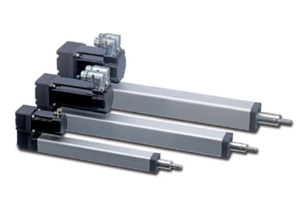
1. The distinction between electric push rod and electric cylinder Electric push rod and electric cylinder are generally referred to as electric actuators. They use an electric motor to drive…
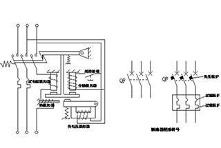
Ever wondered what keeps your home's electrical systems safe and reliable? Low-voltage electrical apparatus, like circuit breakers and contactors, play a crucial role in ensuring this. This article demystifies the…
Have you ever wondered what sets DC motors apart from AC motors? In this article, we explore the fundamental differences between these two types of motors, including their operating principles,…