Exploring Motor Types and Principles in Manufacturing
Imagine the world without the hum of motors—no cars, no appliances, no industrial machines. Motors convert electrical energy into mechanical energy, powering everything from toys to manufacturing giants. In this article, we’ll explore various motor types, their working principles, and their applications. By understanding these fundamentals, you’ll gain insights into how these indispensable devices shape our modern lives and the innovations they drive in the industrial landscape.
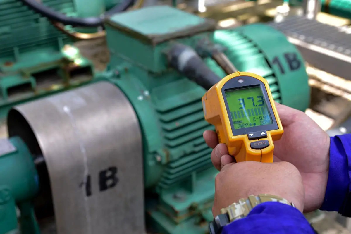
Nearly half of the world’s power consumption is attributed to motors, making the efficient use of motors one of the most effective measures to address global energy issues.
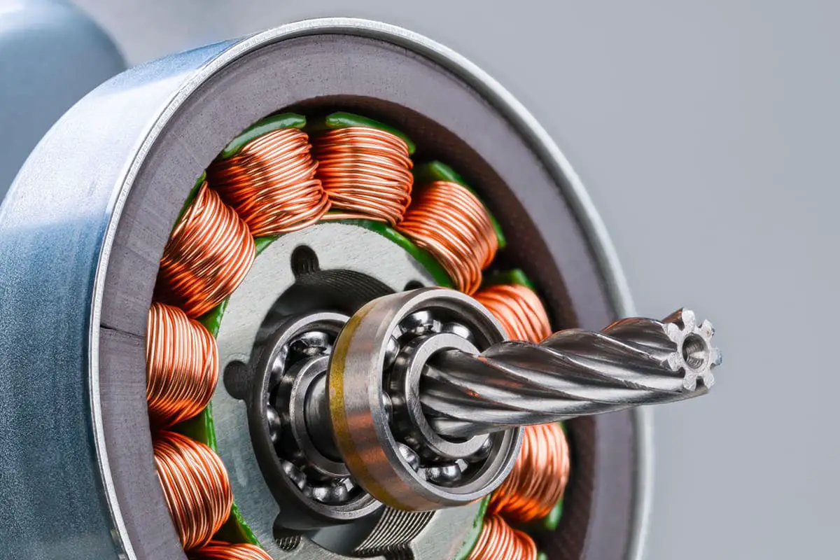
A motor is a device that converts electrical energy into mechanical energy. It utilizes a powered coil (the stator winding) to generate a rotating magnetic field, which acts upon the rotor (such as a squirrel-cage closed aluminum frame) to create a rotating magnetic torque.
Motors are divided into direct current (DC) motors and alternating current (AC) motors based on the type of power supply used. Most of the motors in the power system are AC motors, which can be either synchronous or asynchronous (the rotation speed of the motor stator magnetic field is not synchronized with the rotor rotation speed).
A motor mainly consists of a stator and a rotor. The direction of motion of the powered conductor in the magnetic field is related to the direction of the current and the direction of the magnetic field lines. The working principle of a motor is the force of the magnetic field on the current, causing the motor to rotate.
Motor control refers to the control of the motor’s start, acceleration, operation, deceleration, and stop. There are different requirements and objectives depending on the type of motor and the circumstances in which the motor is used. For motors, through motor control, the goals of rapid start, quick response, high efficiency, high torque output, and high overload capacity are achieved.
The standard motors, servomotors, stepper motors, and servo motors mentioned here refer to DC micromotors, which we often encounter. A motor, also known as a “motor,” refers to this electromagnetic induction device that maintains the transformation or transmission of electromagnetic energy according to Faraday’s law of electromagnetic induction.
A motor, also known as an “electric machine,” is represented in the power circuit by the English letter “M” (formerly represented by “D”). Its main function is to generate driving torque as a power source for electrical appliances or various machines. A generator is represented by the letter “G” in the circuit.
1. Types of Motors
Generally, motors refer to devices that convert the force generated by the flow of electric current in a magnetic field into rotational motion, and in a broader sense, linear motion as well.
Motors can be classified into two categories based on their power source: DC motors and AC motors.
They can also be roughly categorized based on their rotation principles, with a few exceptions for special types of motors.
(1) DC motor
Brushed Motor
The widely used brushed motor is generally referred to as a DC motor. The rotor rotates by switching the current through electrodes called “brushes” (on the stator side) and a “commutator” (on the armature side).
Brushless DC Motor
This motor does not require brushes or a commutator, but instead uses switching functions such as transistors to switch currents and rotate the motor.
Stepper Motor
This motor operates synchronously with pulse power and is therefore also called a pulse motor. Its characteristic is easy and accurate positioning operation.
(2) AC motor
Asynchronous motor
The alternating current causes the stator to produce a rotating magnetic field, which causes the rotor to produce an induced current and rotate under its interaction.
Synchronous motor
AC creates a rotating magnetic field, and the rotor with the magnetic field rotates due to attraction. The rotation rate is synchronized with the power frequency.
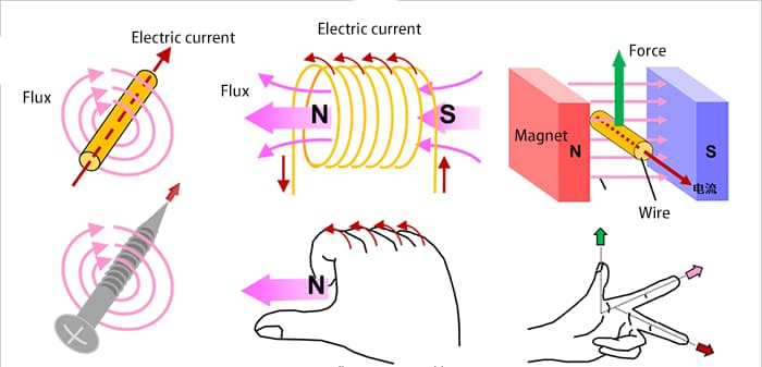
About Electric Current, Magnetic Fields, and Force
Firstly, in order to facilitate the explanation of motor principles, let’s review the basic laws of electric current, magnetic fields, and force. Although it may bring a sense of nostalgia, it is easy to forget this knowledge if one doesn’t frequently use magnetic components.
We will use pictures and formulas to illustrate this.
Schematic diagram of motor rotation
When the wire loop is a rectangle, we need to consider the force acting on the current.
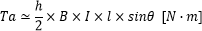
The force F acting on the sides a and c can be calculated by the following formula:
This produces a torque about the central axis.
For example, when considering the state where the rotation angle is only θ, the force acting on b and d at right angles is sinθ. Therefore, the torque Ta on the side a can be expressed by the following formula:
In the same way, considering the side c, the torque doubles and generates a torque calculated by the following formula:
Since the area of the rectangle is S = h x l, substituting it into the above formula yields the following results:
This formula is not only applicable to rectangles but also to other common shapes such as circles. Motors utilize this principle.
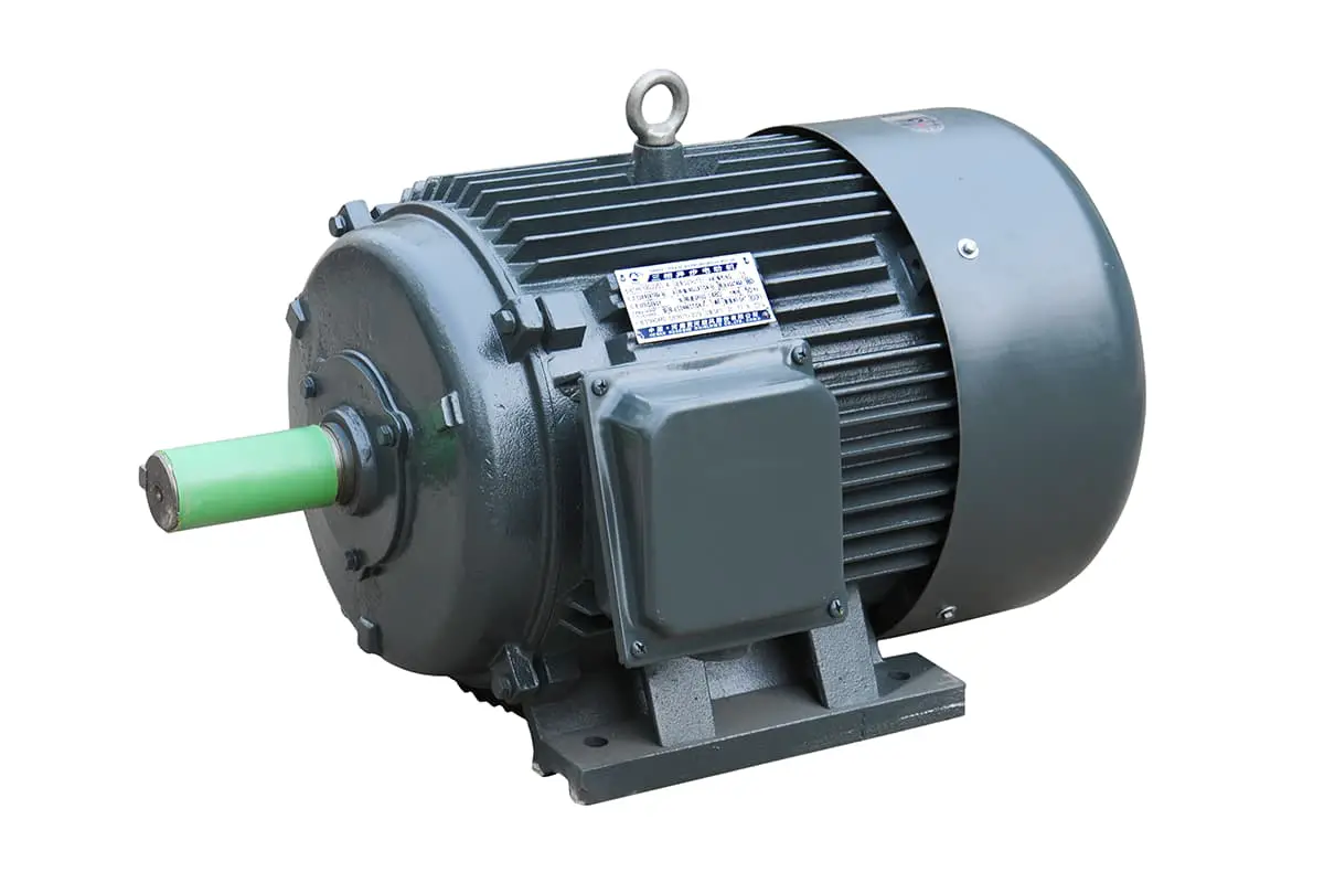
Standard Motor
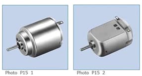
A standard motor, frequently seen in everyday items such as electric toys and electric razors, is typically a direct current brushed motor. Characterized by high speed and low torque, it only requires two pins to operate. When connected to the positive and negative terminals of a battery, the motor starts to rotate. Reversing the connection will cause the motor to rotate in the opposite direction.
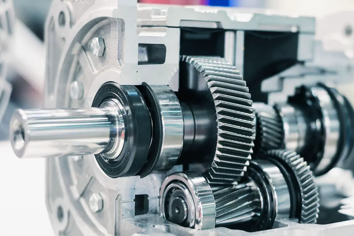
Gear Reduction Motor
A gear reduction motor is a standard motor equipped with a gearbox. This design lowers the rotational speed while increasing the torque, expanding the range of practical applications for the standard motor.
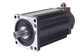
Servo Motor
A servo motor consists mainly of a shell, circuit board, coreless motor, gears, and position detector. It operates by receiving a signal from the receiver to the servo motor. The onboard IC determines the rotation direction and drives the coreless motor to start rotating.
The motion is transmitted to the swing arm through the reduction gears, and the position detector simultaneously sends back signals to verify if the intended position has been reached. The position detector is essentially a variable resistor, which changes resistance values as the servo motor rotates. By detecting these resistance values, the rotation angle can be determined.
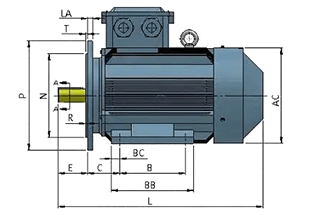
Specifications provided by servo motor manufacturers usually include dimensions (mm), torque (kg/cm), speed (sec/60°), test voltage (V), and weight (g). The unit of torque is kg/cm, indicating how many kilograms can be lifted at a swing arm length of 1 cm.
This is the concept of a leverage arm, therefore, the longer the arm, the lower the torque. The unit of speed is sec/60°, representing the time required for the servo motor to rotate 60°.
Stepper Motor
A stepper motor is an open-loop control element that converts electric pulse signals into angular or linear displacement. Under non-overload conditions, the speed and stopping position of the motor depend solely on the frequency and number of pulse signals, irrespective of load changes.
When a stepper driver receives a pulse signal, it drives the stepper motor to rotate a fixed angle, known as the “step angle,” in a predetermined direction. Its rotation progresses in fixed angle increments. The number of pulses can be controlled to manage angular displacement, achieving precise positioning. Similarly, the pulse frequency can be used to control the rotational speed and acceleration of the motor, thus achieving speed regulation.
A servo motor, also known as an actuator motor, serves as an executing unit in automatic control systems, converting the received electrical signals into an angular displacement or angular velocity output on the motor shaft.
It comes in two main categories: direct current (DC) and alternating current (AC) servo motors. The primary characteristic of these motors is that there is no self-rotation phenomenon when the signal voltage is zero and the rotational speed uniformly decreases as the torque increases.
Servo motors primarily rely on pulses for positioning. Essentially, the servo motor rotates by a pulse-corresponding angle for each pulse received, thereby achieving displacement. Since the servo motor itself has the ability to emit pulses, it emits a corresponding number of pulses for each degree it rotates.
This forms a responsive or ‘closed loop’ system with the received pulses. In this way, the system knows how many pulses have been sent to the servo motor and how many pulses have been received back. Consequently, it can control the rotation of the motor very precisely, enabling precise positioning up to 0.001mm.
Servo motors are broadly divided into AC servo and DC servo categories.
AC servo motors are further divided into asynchronous AC servo motors and synchronous AC servo motors.
DC servo motors are split into brushed and brushless motors. Brushed motors are low-cost, simple in structure, produce a high starting torque, have a wide range of speed control, and are easy to control. They require maintenance, but it’s inconvenient (e.g., brush replacement), and they produce electromagnetic interference and have specific environmental requirements. Therefore, they are suitable for cost-sensitive general industrial and civilian applications.
2. How do Motors Rotate?
1)Motors Rotate with the Help of Magnets and Magnetic Force
Around a permanent magnet with a rotating shaft,
① Rotating the magnet (to produce a rotating magnetic field),
② According to the principle of opposite poles attract and same poles repel between the N pole and S pole,
③ The magnet with the rotating shaft will rotate.
This is the basic principle of motor rotation.
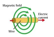
The flow of current through a wire generates a rotating magnetic field (magnetic force) around it, which causes the magnet to rotate.
In fact, this is the same operational state as previously described.
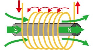
In addition, if the wire is wound into a coil, the magnetic forces are combined to form a large magnetic field flux (magnetic flux), which produces N and S poles.
Inserting an iron core into the coil-shaped wire makes it easier for the magnetic field lines to pass through and generate a stronger magnetic force.
2)Practical Rotating Motors
Here, we will introduce the practical method of using three-phase AC and coils to produce a rotating magnetic field as a rotating motor.
(Three-phase AC is an AC signal with a phase difference of 120°.)
The combined magnetic field in the above state ① corresponds to the figure ① below.
The combined magnetic field in the above state ② corresponds to the figure ② below.
The combined magnetic field in the above state ③ corresponds to the figure ③ below.
As mentioned above, the coil wound around the iron core is divided into three phases, with U-phase coil, V-phase coil, and W-phase coil arranged at 120° intervals.
The coil with high voltage generates an N pole, while the coil with low voltage generates an S pole.
Each phase changes according to a sine wave, so the polarity (N pole, S pole) and magnetic field (magnetic force) of each coil will change.
At this time, if we look at the coil that produces an N pole, it changes sequentially from U-phase coil to V-phase coil to W-phase coil to U-phase coil, causing rotation.
3. Structure of Small Motors
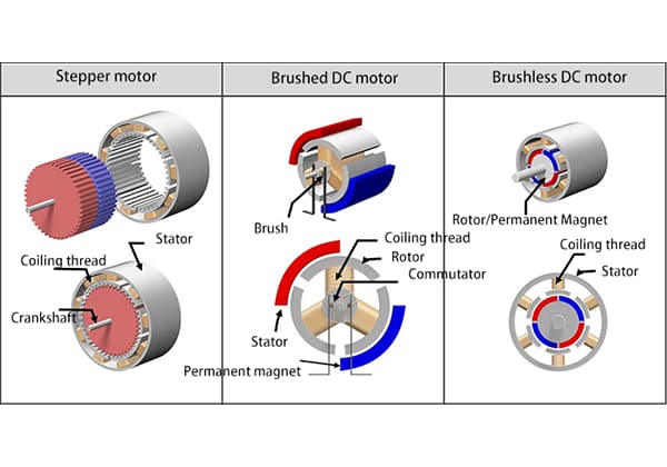
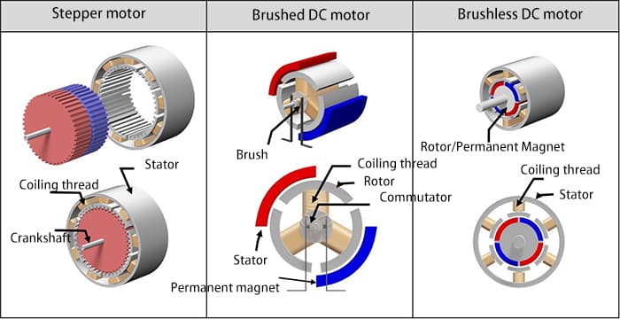
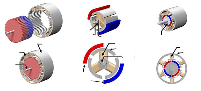
The following figure shows the approximate structures and comparisons of three types of motors: the stepping motor, the brushed DC motor, and the brushless DC motor.
The basic components of these motors are mainly coils, magnets, and rotors, and they are classified as coil-fixed type and magnet-fixed type due to their different types.
The following is a structural explanation related to the example diagram. As there may be other structures if we divide them more finely, please understand that this article describes the overall structure.
In the stepping motor shown here, the coil is fixed on the outer side and the magnet rotates on the inner side.
In the brushed DC motor shown here, the magnet is fixed on the outer side and the coil rotates on the inner side. The brushes and the commutator are responsible for supplying power to the coil and changing the direction of the current.
In the brushless motor shown here, the coil is fixed on the outer side and the magnet rotates on the inner side.
Due to the different types of motor, even if the basic components are the same, the structure may be different. The detailed explanation will be given in each section.
4. Brushed Motor
Structure of Brushed Motor
Shown below is the appearance of a brushed DC motor frequently used in models, as well as an exploded diagram of a typical two-pole (2 magnets) and three-slot (3 coils) motor. Many people may have experience dismantling motors and removing magnets.
As can be seen, the permanent magnet of a brushed DC motor is fixed, and the coils can rotate around the internal center of the motor. The fixed side is called the “stator,” while the rotating side is called the “rotor.”
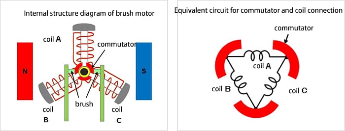
The following is a schematic diagram representing the concept of the motor’s structure.
There are three commutators (curved metal plates for switching the current) on the periphery of the rotating central axis. To prevent them from contacting each other, the commutators are arranged at intervals of 120 degrees (360 degrees ÷ 3). The commutators rotate along with the rotation of the axis.
Each commutator is connected to one coil end and another coil end, and the three commutators and three coils form a circuit network as a whole (ring-shaped).
Two brushes are fixed at 0° and 180° to contact the commutators. The external DC power supply is connected to the brushes, and the current flows along the path of brush → commutator → coil → brush.
Operating principle of a brushed motor.
① Counterclockwise Rotation from Initial State
In the initial state, Coil A is at the top, and the power supply is connected to the brushes with the left (+) and right (-) sides defined. A large current flows from the left brush through the commutator to Coil A, and the upper (outer) side of Coil A becomes an S pole structure.
Since half of the current flowing through Coil A from the left brush towards Coils B and C is in the opposite direction to that of Coil A, the outer side of Coils B and C becomes a weaker N pole (represented by smaller letters in the diagram).
The magnetic fields generated in these coils and the repulsion and attraction between the magnets cause the coil to rotate counterclockwise.
② Further Counterclockwise Rotation
Assuming Coil A is in a state of counterclockwise rotation of 30 degrees, the right brush contacts two commutators.
The current in Coil A continues to flow from the left brush through the right brush, and the outer side of Coil A remains an S pole.
The same current as in Coil A flows through Coil B, and the outer side of Coil B becomes a stronger N pole.
Since both ends of Coil C are short-circuited by the brushes, no current flows, and no magnetic field is generated.
Even in this case, the coil is subjected to a counterclockwise rotational force.
From ③ to ④, the upper coil continues to be subjected to a leftward force and the lower coil continues to be subjected to a rightward force, continuing to rotate counterclockwise.
Each time the coil rotates 30 degrees to states ③ and ④, the outer side of the coil becomes an S pole when the coil is located above the center horizontal axis, and an N pole when the coil is located below it, repeatedly performing this motion.
In other words, the upper coil repeatedly receives a leftward force, and the lower coil repeatedly receives a rightward force (both in a counterclockwise direction). This causes the rotor to continuously rotate counterclockwise.
If the power supply is connected to the opposite left brush (-) and right brush (+), the coil generates a magnetic field in the opposite direction, and the direction of force applied to the coil is reversed, causing clockwise rotation.
Additionally, when the power supply is disconnected, the rotor of the brushed motor stops rotating because there is no magnetic field to keep it rotating.
5. Three-Phase Full-Wave Brushless Motor
Appearance and Structure of Three-Phase Full-Wave Brushless Motor
The following figure shows an example of the appearance and structure of a brushless motor.
On the left is an example of a spindle motor for rotating discs in a disc playback device. There are a total of nine coils, consisting of three phases times three.
On the right is an example of a spindle motor for an FDD device, which has 12 coils (three phases times four). The coils are fixed on the circuit board and wound around an iron core.
The disk-shaped component to the right of the coil is a permanent magnet rotor. The outer edge is made of a permanent magnet, and the rotor shaft is inserted into the center of the coil and covers part of it. The permanent magnet rotates around the outer edge of the coil.
The internal structure diagram of a three-phase full-wave brushless motor and the equivalent circuit for coil connections.
The following are simplified diagrams of the internal structure and equivalent circuit for coil connections.
The simplified diagram shows a 2-pole (2 magnets) 3-slot (3 coils) motor with a simple structure. It is similar to a brushed motor structure with the same number of poles and slots, but the coil side is fixed while the magnets can rotate. Of course, there are no brushes.
In this case, the coils are connected in a Y-shaped configuration, and semiconductor components are used to supply current to the coils. The current flow is controlled based on the position of the rotating magnets.
In this example, Hall elements are used to detect the position of the magnets. The Hall elements are placed between the coils and detect the voltage generated by the magnetic field strength, which is used as position information. In the image of the spindle motor for the FDD device provided earlier, Hall elements can also be seen between the coils for position detection (above the coils).
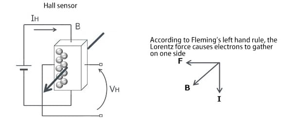
Hall elements are well-known magnetic sensors that convert the size of the magnetic field into the size of the voltage, and represent the direction of the magnetic field with positive or negative voltage.
The following is a schematic diagram illustrating the Hall effect.
The Hall element utilizes the phenomenon that “when a current IH passes through a semiconductor and a magnetic flux B passes through perpendicular to the current, a voltage VH is generated in the direction perpendicular to both the current and the magnetic field.” American physicist Edwin Herbert Hall discovered this phenomenon and named it the “Hall effect.” The voltage VH generated is expressed by the following formula:
VH = (KH / d)・IH・B
※KH: Hall coefficient, d: thickness of the magnetic flux penetration surface
As shown in the formula, the higher the current, the higher the voltage. This characteristic is commonly used to detect the position of the rotor (magnet).
Rotational principle of three-phase full-wave brushless motors
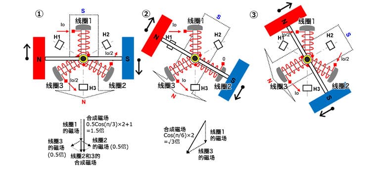
The rotational principle of a brushless motor will now be explained in steps 1 to 6. To make it easier to understand, the permanent magnet has been simplified from a circular shape to a rectangular shape.
① In a three-phase coil system, coil 1 is fixed at the 12 o’clock position, coil 2 is fixed at the 4 o’clock position, and coil 3 is fixed at the 8 o’clock position on the clock face. A 2-pole permanent magnet with its N pole on the left and S pole on the right is able to rotate.
Pass a current Io through coil 1 to produce an S pole magnetic field on the outside of the coil. Pass a current of Io/2 through coils 2 and 3 to produce an N pole magnetic field on the outside of the coil.
When the magnetic fields of coils 2 and 3 are vectorially combined, an N pole magnetic field pointing downwards is produced. This magnetic field is 0.5 times the magnetic field produced by the current Io passing through a single coil, and when added to the magnetic field of coil 1, it becomes 1.5 times stronger. This produces a combined magnetic field perpendicular to the permanent magnet, which generates maximum torque and causes the permanent magnet to rotate clockwise.
As the current through coil 2 is reduced and the current through coil 3 is increased based on the rotation position, the combined magnetic field also rotates clockwise, causing the permanent magnet to continue to rotate.
② In a rotated state of 30 degrees, a current Io is passed through coil 1, making the current in coil 2 zero and causing the current Io to flow out of coil 3.
The outside of coil 1 becomes an S pole and the outside of coil 3 becomes an N pole. When vectorially combined, the magnetic field produced is √3 (≈1.72) times stronger than the magnetic field produced by the current Io passing through a single coil. This also produces a combined magnetic field perpendicular to the permanent magnet, which rotates clockwise.
As the rotation position changes, the current flowing into coil 1 is reduced, the current flowing into coil 2 starts from zero and increases, and the current flowing out of coil 3 increases to Io. As a result, the combined magnetic field also rotates clockwise, causing the permanent magnet to continue to rotate.
※ Assuming that each phase current is a sine wave, the current value here is Io × sin(π⁄3) = Io × √3⁄2. Through vectorial combination of the magnetic fields, the total magnetic field magnitude is 1.5 times the magnetic field produced by a single coil.
When each phase current is a sine wave, regardless of the position of the permanent magnet, the magnitude of the vectorially combined magnetic field is always 1.5 times the magnetic field produced by a single coil, and the magnetic field is perpendicular to the permanent magnet’s magnetic field at a 90-degree angle.
③ In a continued rotation of 30 degrees, a current of Io/2 flows through coil 1, a current of Io/2 flows through coil 2, and a current of Io flows out of coil 3.
The outside of coil 1 becomes an S pole, the outside of coil 2 also becomes an S pole, and the outside of coil 3 becomes an N pole. When vectorially combined, the magnetic field produced is 1.5 times the magnetic field produced when a current of Io passes through a single coil (same as in step 1). This also produces a combined magnetic field perpendicular to the permanent magnet’s magnetic field at a 90-degree angle and rotates clockwise.
④-⑥
Continue rotating in the same manner as steps 1-3.
In this way, if the current flowing into the coils is continuously switched based on the position of the permanent magnet, the permanent magnet will rotate in a fixed direction. Similarly, if the current is made to flow in the opposite direction and the direction of the combined magnetic field is reversed, the rotation will be counterclockwise.
The following diagram shows the current flowing through each coil for each step from 1 to 6.
Through the above explanation, the relationship between current changes and rotation should now be understood.
6. Stepper Motor
A stepper motor is a type of motor that can be precisely controlled in terms of rotation angle and speed by synchronizing with a pulse signal. Stepper motors are also known as “pulse motors”.
Due to their ability to achieve accurate positioning without the use of position sensors and with only open-loop control, stepper motors are widely used in equipment that requires positioning.
Structure of Stepper Motor (Two-phase bipolar)
The following images from left to right show examples of the appearance of a stepper motor, a schematic diagram of its internal structure, and a conceptual diagram of its structure.
In the appearance example, both the HB (hybrid) and PM (permanent magnet) types of stepper motors are shown. The schematic diagram in the middle also shows the structure of both the HB and PM types.
A stepper motor has a structure in which the coils are fixed and the permanent magnet rotates. The conceptual diagram of the internal structure of the stepper motor on the right is an example of a PM motor with two-phase (two sets) coils.
In the example of the basic structure of the stepper motor, the coils are arranged on the outside and the permanent magnet is arranged on the inside. In addition to the two-phase type, there are types with more phases such as three-phase and five-phase.
Some stepper motors have different structures, but for the sake of explaining the basic working principle of stepper motors, this article presents the stepper motor with the basic structure of fixed coils and rotating permanent magnets.
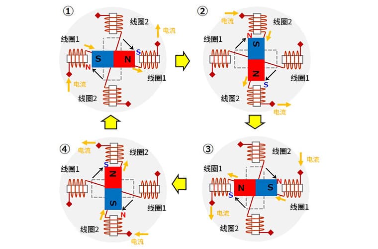
The following diagram is used to explain the basic working principle of the stepper motor. This is an excitation example of each phase (one set of coils) of the two-phase bipolar coils shown in the previous image, assuming a state change from ① to ④. The coils are composed of coils 1 and 2, and the current arrow indicates the direction of current flow.
①
Electric current flows from the left side of coil 1 and exits from the right side.
Do not allow electric current to flow through coil 2.
At this point, the inside of the left coil 1 becomes North, and the inside of the right coil 1 becomes South.
As a result, the middle permanent magnet is attracted by the magnetic field of coil 1 and stops in a state where the left side is South and the right side is North.
②
Stop the current in coil 1 and allow current to flow from the top of coil 2 and exit from the bottom.
The inside of the top coil 2 becomes North, and the inside of the bottom coil 2 becomes South.
The permanent magnet is attracted by its magnetic field and rotates 90° clockwise and stops.
③
Stop the current in coil 2 and allow current to flow from the right side of coil 1 and exit from the left side.
The inside of the left coil 1 becomes South, and the inside of the right coil 1 becomes North.
The permanent magnet is attracted by its magnetic field and rotates another 90° clockwise and stops.
④
Stop the current in coil 1 and allow current to flow from the bottom of coil 2 and exit from the top.
The inside of the top coil 2 becomes South, and the inside of the bottom coil 2 becomes North.
The permanent magnet is attracted by its magnetic field and rotates another 90° clockwise and stops.
By switching the current flowing through the coils in the order of steps ① to ④ using electronic circuits, the stepper motor can be rotated. In this example, each switching action will rotate the stepper motor by 90°.
Additionally, by continuously flowing current through a particular coil, the stepper motor can maintain its stopped position and have holding torque. It’s worth mentioning that reversing the order of the current flowing through the coils can make the stepper motor rotate in the opposite direction.
As the founder of MachineMFG, I have dedicated over a decade of my career to the metalworking industry. My extensive experience has allowed me to become an expert in the fields of sheet metal fabrication, machining, mechanical engineering, and machine tools for metals. I am constantly thinking, reading, and writing about these subjects, constantly striving to stay at the forefront of my field. Let my knowledge and expertise be an asset to your business.
Have you ever wondered what keeps an electric motor running smoothly without overheating? Understanding the safe operating temperatures for motors is crucial for their longevity and performance. In this article,…
Ever wondered how machines achieve precise movements? This blog dives into the fascinating world of servo motor control modes. From pulse to analog control, we'll explore how each method works…
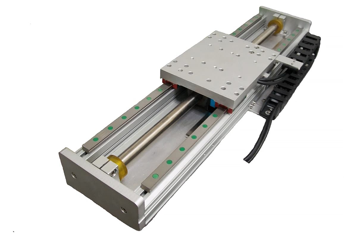
Ever wondered how trains can float above tracks or how robots achieve precise movements? This article unveils the fascinating world of linear motors, explaining their principles, types, and unique advantages.…
Ever wondered how to pick the perfect motor for your project? The key lies in understanding the types of motors—DC, asynchronous, and synchronous—and their unique advantages. This article breaks down…
Why do motor bearings get so hot, and what can be done about it? This article dives into the causes of motor bearing heat generation, from excessive loads and poor…
What happens when a motor's magnetic balance is off? Unilateral magnetic pull occurs due to an imbalanced air gap in motors, causing uneven forces that strain motor bearings. This article…
How do bearings impact the efficiency and durability of helical gear motors? This article delves into the critical role of bearings, discussing their selection and arrangement, and how they handle…
Imagine a world where machines not only build our products but also think and learn like us. In this article, we explore how artificial intelligence is transforming the manufacturing industry.…
Have you ever wondered how everyday objects are meticulously crafted from metal? This article unravels 444 essential concepts in mechanical manufacturing, from riveting techniques to the nuances of welding machines.…