Abrasive Water Jet Cutting Technology: What You Need to Know
Imagine cutting through steel or marble with nothing more than a jet of water. This is the power of abrasive water jet technology, a groundbreaking method that uses high-pressure water…
Imagine a cutting technique so precise it revolutionizes the production of essential motor and transformer components. Water cutting of silicon steel sheets does just that, offering superior quality and efficiency. This article dives into how this innovative method enhances production, reduces costs, and extends the life of silicon steel sheets. Get ready to explore the intricacies of water cutting and discover why it’s becoming a game-changer in the manufacturing industry.

The traditional method for producing silicon steel sheets, which are used in motors and electrical appliances, involves the installation of molds on mechanical presses.
The cold stamping die of silicon steel sheet is mainly composed of male and female dies, which are installed on the press to punch the silicon steel sheet into the motor stator and rotor or transformer iron chip.
During the operation of a silicon steel sheet die, the edge is subject to impact, shear, and bending forces. Additionally, the edge is also squeezed and rubbed by the silicon steel sheet. A special coating on the surface of the silicon steel sheet enhances the friction and wear of the edge, which is the main reason for the die’s normal failure.
As a result, die wear is severe, and it often needs to be sharpened before reaching its ideal service life. The number of punched parts in a set of dies is often less than its theoretical value.
For instance, consider the blanking process of a certain motor’s silicon steel sheet. It requires seven types of dies to complete, with a total cost of 190,000 yuan. The hardness of a stamping die for a rotor sheet is 60 to 62Hrc and is installed on a 60t stamping machine tool. Typically, the die can punch more than 200,000 pieces.
However, the slot hole’s edge of the die collapses after being used less than 9,000 times. Grinding the die (usually after 50,000 to 60,000 times) and reapplying it on the machine doesn’t solve the problem. Instead, the collapse persists, and cracks appear on the die’s outer edge.
During continuous stamping, the cracks rapidly expand, and the die fails, becoming unusable after fewer than 20,000 uses. Each time two motors are produced, three types of molds require sharpening, costing between 400 and 800 yuan each time, making the product manufacturing cost relatively high.
Especially during new product trial production, mold manufacturing costs are considerably high, and the production cycle is long, doubling the new product development cost.
Silicon steel sheet is a crucial component of motors and electrical appliances. Its performance directly affects the loss of electric energy and the efficiency, size, and weight of products such as transformers.
Therefore, silicon steel sheet should generally meet the following requirements:
The blanking process of silicon steel sheet should not only have the typical characteristics of metal shearing but also satisfy the following special requirements.
The height of the burr on the silicon steel sheet used for blanking should not exceed 0.05mm. The impact of burrs on the performance of the entire machine’s mechanical parts is receiving more attention.
The electromagnetic characteristics of generators, motors, and transformers that use silicon steel sheets are significantly affected by burrs.
Die blanking is used to form the silicon steel sheets used in generators, motors, and transformers. Often, the die manufacturing gap is too large, or it increases due to wear.
During the blanking process, the silicon steel sheet is extruded, causing slight plastic deformation. This deformation remains on the sheet’s edge, resulting in the formation of burrs.
Generators’ rotor, stator, and transformer core use a large number of blanking silicon steel sheets that have burrs.
Burr on the silicon steel sheet reduces the stacking factor. To install the same number of sheets, the motor volume must increase.
Furthermore, the burr affects the motor’s output power. It has been demonstrated that the generator’s output power can increase by 0.1% to 0.2% by using deburred silicon steel sheets compared to generators that don’t use deburred silicon steel sheets.
The presence of burrs on silicon steel sheets creates significant gaps between laminations, which can lead to the production of eddy currents, increased magnetic loss, higher temperatures, noise, and even short circuits, resulting in motor failure.
Motors with deburred silicon steel sheets have an average service life that is more than 5% longer compared to those without deburring.
Processed silicon steel sheets can be stacked manually or automatically, and the gap at the joint must be minimized. This requires equipment to maintain high accuracy, including spare parts accuracy, when reaching maximum production capacity. This ensures that the products are virtually free of burrs after shearing (the burr height after longitudinal shearing of silicon steel sheet should not exceed 0.05mm).
Otherwise, during lamination, burrs can cause lap short circuits between the laminations, increase eddy current loss, and reduce the filling coefficient of the lamination.
China’s relevant standards clearly state that the burr height of silicon steel sheets should not exceed 0.05mm. However, many motor factories have not implemented effective deburring measures. They still install and use sheets with burrs as high as 0.07~0.1mm, which seriously affects quality.
Furthermore, the insulating paint film on the surface of the silicon steel sheet should not be visibly scratched during deburring.
After cutting, stamping, and stacking, silicon steel sheets undergo internal stress that deforms the grains, reduces permeability, and increases specific iron loss.
To avoid or minimize these effects, cold-rolled oriented silicon steel sheets are typically treated with nitrogen-filled annealing at a temperature of approximately 800°C after shear processing. This treatment eliminates the stress generated during processing and ensures that the original properties are retained.
Although tests have shown that the specific iron loss of cold-rolled oriented silicon steel sheet after annealing is reduced by around 30%, many manufacturers opt not to adopt this process due to the associated cost increase.
Given the specialized performance requirements of silicon steel sheets, it is crucial to maintain high standards for their production.
These standards must surpass even the American Society for Testing and Materials (ASTM) side bending criteria for general sheared metal, which sets a limit of no more than 6mm/3M in length. As a result, the shear process layout for silicon steel sheets needs to meet even more stringent requirements.
The silicon steel sheet that has been sheared must be free from any visible waves, which are commonly referred to as lotus leaf edge.
In the event of waves, the ratio of wave height to wavelength must not exceed 2.5%.
If this condition is not met, the silicon steel sheet will undergo severe plastic deformation, which will result in damage to the domain structure and a significant increase in loss.
Insulation damage is not permissible within the shearing range or on the surface of the strip. Additionally, the edge of the sheet must be free of any extrusion damage, as failure to meet these criteria may adversely affect the quality of the iron core.

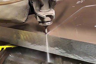
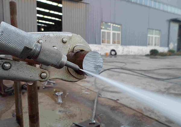
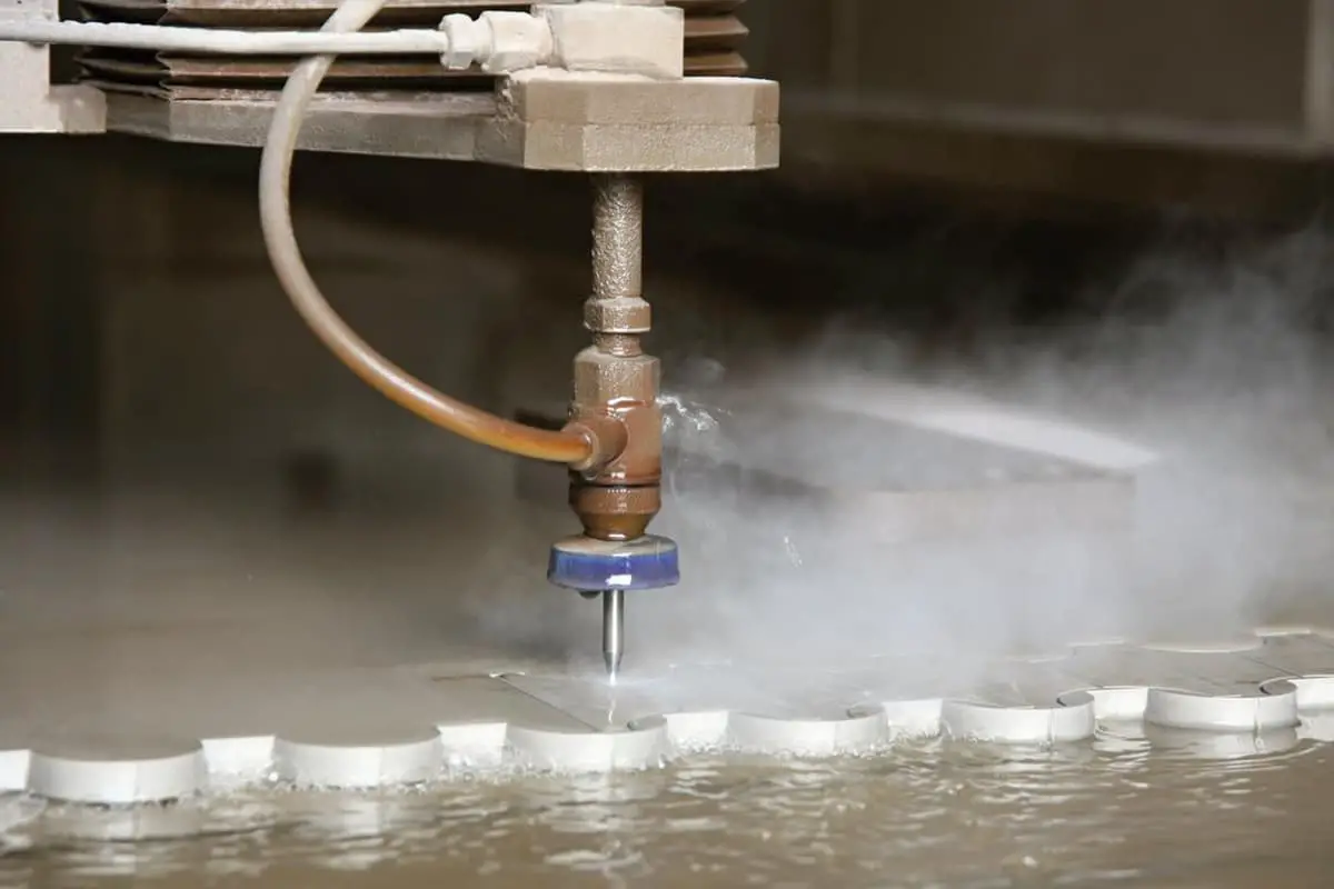
Ultra-high-pressure water cutting, also known as water knife or water jet, is a process that generates a high-energy water flow by pressurizing ordinary water through multiple stages. This water flow is then directed through a fine nozzle to cut materials at a speed of almost a kilometer per second.
This cutting technique is referred to as ultra-high-pressure water cutting. Its origin can be traced back to Scotland, where it was discovered. Over a period of 100 years, experimental research led to the development of an industrial high-pressure water cutting system.
High-pressure water cutting is not patented. However, in 1968, a professor at Columbia University in the United States introduced abrasives to the high-pressure water, which accelerated the cutting process by grinding the materials with the abrasive and the high-pressure water jet.
Today, the United States, Germany, Russia, and Italy have achieved breakthroughs in ultra-high-pressure water cutting technology, with a maximum cutting pressure of 550MPa. This method is widely used for cutting materials such as stone, metal, glass, ceramics, cement products, paper, food, plastics, cloth, polyurethane, wood, leather, rubber, ammunition, and more.
There are three main uses of water cutting:
Firstly, cutting non-combustible materials such as marble, ceramic tiles, glass, cement products, and other materials that cannot be processed by thermal cutting.
Secondly, cutting combustible materials like steel plates, plastic, cloth, polyurethane, wood, leather, rubber, etc. In the past, thermal cutting could also process these materials, but it often resulted in combustion areas and burrs. Water cutting, on the other hand, doesn’t produce such problems, and the physical and mechanical properties of the cut materials remain unchanged, which is a significant advantage of water cutting.
Thirdly, cutting flammable and explosive materials like ammunition and cutting in flammable and explosive environments cannot be replaced by other processing methods.
In terms of water quality, ultra-high pressure water cutting is available in two forms: pure water cutting and abrasive cutting.
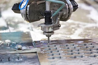
The water-cutting test for silicon steel sheet is carried out using the Altorf water knife as the main equipment.
The high voltage generator (APW38037Z-09A) of the equipment is equipped with a complete set of originally imported superchargers from AccuStream Inc.
The control system uses PLC instead of relay to achieve communication and flexible control with the computer.
The cutting platform (APW-2030BA) has a gantry structure, which makes it more stable and accurate compared to a cantilever structure.
The equipment is equipped with an industrial PC platform with special water cutting software based on Windows and supported by a genuine Windows XP system.
The linear part of the cutting process has a speed of 800mm/min, while the circular arc part has a speed of 300mm/min. The thickness of the silicon steel sheet used in the test is 0.5mm.
After the test, the product is retrieved from the water tank of the cutting platform, dried, and its size checked. The product had an out-of-tolerance issue only at the knife entry during round hole cutting. This issue was mainly caused by too fast knife entry during programming, making the hole feel elliptical. During the retest, this phenomenon disappeared, and the burr was less than 0.05mm. The product could be stacked without grinding, and the rest of the product met the requirements of the drawing.
The test results of the water-cutting process for silicon steel sheets indicate that optimal product quality can be achieved by utilizing appropriate cutting process parameters, closely monitoring the water quality and sand particle size, and controlling the inlet speed and direction of the arc.
Water cutting offers several advantages, such as high speed, excellent quality, cost savings, and easy product modification. Additionally, it proves especially useful during trial production of new products since there is no need for molds. This significantly reduces the production preparation cycle and minimizes the initial investment required for new products. The results of such trials have been highly satisfactory.

As the founder of MachineMFG, I have dedicated over a decade of my career to the metalworking industry. My extensive experience has allowed me to become an expert in the fields of sheet metal fabrication, machining, mechanical engineering, and machine tools for metals. I am constantly thinking, reading, and writing about these subjects, constantly striving to stay at the forefront of my field. Let my knowledge and expertise be an asset to your business.