Inside Micrometer Instruction Manual: A Step-by-Step Guide
Have you ever struggled to measure the inside dimensions of an object with precision? The inside micrometer, a versatile tool for internal measurements, is essential for achieving high accuracy in mechanical processing. This article will guide you through its structure, technical data, and proper usage, ensuring you can confidently measure inner diameters and distances between parallel planes. By the end, you’ll understand how to handle and maintain this instrument to get reliable results every time.
The Inside Micrometer is a universal internal dimensional measurement tool that uses the principle of a screw pair to read the distance between the spherical measuring surfaces at both ends of the main body. It is especially suitable for measuring the inner diameter, groove, and distance between two parallel planes in mechanical processing. The accuracy level measured is generally IT8-IT10 as specified in GB/T1800.3-1998.
The center of the measuring head of the inside micrometer is set with a hard alloy sheet, which extends the service life of the inside micrometer.
The driving mechanism of the inside micrometer is composed of a micrometer screw and a threaded shaft sleeve fixed in the fixed sleeve; the differential, calibration nut, and micrometer screw are fastened together as moving parts; The measuring head, threaded shaft sleeve, fixed sleeve, etc. are connected as a fixed part. The inside micrometer has a compact structure and stable and reliable measurement accuracy.
All accuracy indicators meet national standards.
Users can choose the appropriate micrometer based on their measurement needs or place special orders according to their requirements. The specific specifications and graduation values are shown in Table 1.
Table 1
Series and indicators
Lower limit of measurement
50
150
250
Individual inner diameter
Measuring range of micrometer head
13
25
50
25
Graduation value
0.01
0.01
0.01
0.01
Specification (measurement range)
50-250 50-600 50-1000 50-1500
150-1500 150-2000 150-3000
250-2000 250-3000 250-4000 250-5000 250-6000
50-75 75-100 275-300
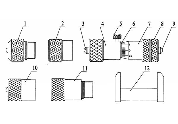
2. Structural Diagram
1. Measuring contact
2. Connecting sleeve
3. Measuring head
4. Threaded shaft sleeve
5. Locking screw
6. Fixed sleeve
7. Differential
8. Calibration nut
9. Micrometer screw
10. Measuring head
11. Connecting rod
12. Calibration clamp
3.Technical data
Technical data
Measuring range
50~75
75~125
>125~200
>200~325
>325~500
>500~600
Graduation value
0.01
0.01
0.01
0.01
0.01
0.01
Indication error
±0.006
±0.006
±0.008
±0.010
±0.012
±0.016
Measure the spherical radius of the surface
20
20
20
20
20
20
The range of the micrometer screw is 13
Check the size and deviation of the card board by 50 ± 0.002
4. Instructions for Use
Observe whether there are any defects on the appearance of the Inside Micrometer that may affect the measurement. Clean the measuring contacts, measuring heads, and measuring heads, rotate the differential to check if it rotates flexibly, and check if the locking device is firmly fixed.
Before using the Inside Micrometer, use the calibration clamp to calibrate the zero position of the micrometer head (combination of 3-9 components), and apply even force.
If there is a slight error, first tighten the locking screw and then loosen the calibration nut to align the zero position of the differential cylinder with the longitudinal line of the fixed sleeve, and finally tighten the calibration nut.
When connecting the connecting rod to the Inside Micrometer during use, first unscrew the nut on the threaded shaft sleeve, and then tighten the right end of the connecting rod to the left end of the threaded shaft sleeve.
When using the Inside Micrometer to measure the aperture, support the measuring surface of the measuring contact on the measured surface, adjust the differential, and swing the measuring surface on one side of the differential cylinder in the radial section of the hole to find the maximum size, and then swing it in the axial section of the hole to find the minimum size. This adjustment needs to be repeated several times.
Finally, tighten the locking screw, remove the Inside Micrometer, and read the measurement. When measuring the distance between two parallel planes, swing the Inside Micrometer in multiple directions and take the smallest size as the measurement result.
5. Precautions
The Inside Micrometer can not only be used with a connecting rod for internal diameter and internal dimensional measurement but the micrometer head (combination of 3-9 components) can also be used as a single Inside Micrometer.
When using the Inside Micrometer, select the appropriate connecting rod from the provided connecting rod comparison table to form the required size to reduce cumulative errors. Also, connect the largest connecting rod to the micrometer head, and then sequentially connect to the measuring contact to reduce the bending of the axis after connection.
When using the Inside Micrometer to measure the aperture, at least one cross-section should be measured in two perpendicular directions. For deep hole measurements, the number of supporting faces should be appropriately increased.
Pay attention to the influence of temperature during measurement and prevent heat transfer from the hand or other heat sources. Especially for large-size measurements, special attention should be paid.
The support position of the Inside Micrometer during measurement should be correct. When measuring with a long-length Inside Micrometer, support it at 0.211L on both ends of the full-length size. This reduces deformation and minimizes measurement errors.
After measurement, the Inside Micrometer should be placed flat to avoid deformation of the instrument.
During use, be careful not to bump the micrometer. Before assembling the connecting rod, wipe clean all contact surfaces and measuring surfaces. After use, apply rust-proof oil to each measuring surface, and store them in a box.
The connecting rod comparison table is attached below.
Except for the (50-70) mm measurement range, all other components are connected to the micrometer head with a connecting sleeve.
Comparison Table for Extension Rod of (50-600) mm Inner Diameter Micrometer
As the founder of MachineMFG, I have dedicated over a decade of my career to the metalworking industry. My extensive experience has allowed me to become an expert in the fields of sheet metal fabrication, machining, mechanical engineering, and machine tools for metals. I am constantly thinking, reading, and writing about these subjects, constantly striving to stay at the forefront of my field. Let my knowledge and expertise be an asset to your business.
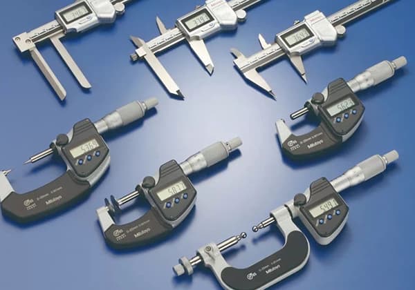
When it comes to precise measurements, should you reach for a Vernier caliper or a micrometer? Both tools are essential in various industries, but each has its strengths. This article…
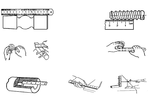
Ever wondered how precise measurements shape the world of mechanical engineering? This article explores essential tools like steel rulers, calipers, and vernier calipers, revealing their uses and accuracy. Learn how…
How do you measure the intricate curves and grooves of a complex workpiece? Standard tools fall short, making precise measurement difficult. This article delves into specialized instruments designed for these…
Have you ever wondered why your machinery fails prematurely? This article uncovers the common issue of bearing misalignment and offers practical methods to inspect, diagnose, and correct it. Learn how…
I. What Is Nondestructive Testing? Nondestructive testing is a general term that refers to all technical means used to detect defects or nonuniformity in an object being tested, by utilizing…
Imagine a world where nearly anything can be created layer by layer, from intricate medical implants to entire houses. This is the power of 3D printing. Our article explores the…