Have you ever wondered what holds our world together, from towering skyscrapers to everyday gadgets? This blog post will unravel the fascinating world of fasteners, exploring their types, uses, and essential characteristics. Get ready to learn how these small components play a big role in engineering and everyday life!
Fasteners are a common component that everyone should be familiar with.
In this article, we will introduce fasteners from four perspectives: classification of fasteners, identification and inspection of threads, material requirements, heat treatment requirements, and mechanical performance requirements for bolts, screws, and studs, as well as the types and structure of steel structure bolts.
I. Classification of Fasteners
What are Fasteners?
Fasteners are mechanical components used to securely join two or more parts or components into a single unit. They are also commonly referred to as standard parts on the market.
Types of Fasteners:
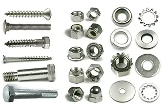
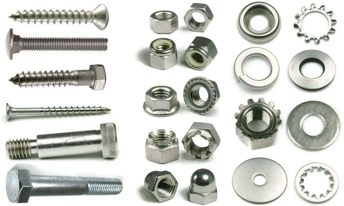
Fasteners usually include the following twelve types of parts: Bolts, studs, screws, nuts, self-tapping screws, wood screws, washers, retaining rings, pins, rivets, complete assemblies, and connecting pairs, as well as welding nails.
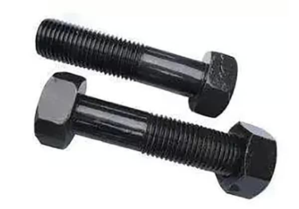
(1) Bolts:
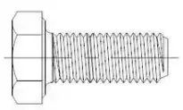
Bolts are a type of fastener consisting of a head and a screw (cylinder with an external thread) that requires a nut to secure two parts with through holes. This type of connection is known as a bolt connection and is a removable connection as the two parts can be separated if the nut is unscrewed from the bolt.
As shown below:
Fig. 2-1-1 full thread of outer hexagon head bolt
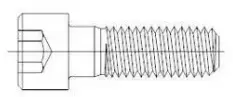
Fig. 2-1-2 half tooth of hexagon socket bolt with cylindrical head
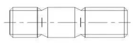
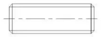
(2) Stud:
A stud is a fastener that has external threads on both ends and does not have a head. When connecting, one end is screwed into a part with an internal threaded hole, while the other end passes through a part with a through hole, and is then secured by a nut. This results in a firmly connected whole.
This type of connection is referred to as a stud connection and, like the bolt connection, is a removable connection. Studs are mainly used when one of the connected parts is thick, requires a compact structure, or frequent disassembly makes a bolt connection unsuitable.
As shown below:
Fig. 2-2-3 double head stud
Fig. 2-2-4 full thread stud
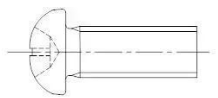
(3) Screw:
A screw is a fastener made up of a head and a screw. It can be divided into three categories based on its purpose: steel structure screw, set screw, and special-purpose screw.
Machine screws are mainly used to fasten a part with a fixed threaded hole to a part with a through hole without the need for a nut (this type of connection is known as a screw connection and is also a removable connection). Machine screws can also be used with nuts to secure two parts with through holes.
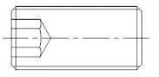
Set screws are used primarily to fix the relative position between two parts.
Special-purpose screws, such as eyebolts, are used for hoisting components.
As shown below:
Fig. 2-3-5 pan head screw
Fig. 2-3-6 hexagon socket set screw
Fig. 2-3-7 eyebolt
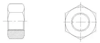
(4) Nut:
A nut is a component that has an internal threaded hole and is typically shaped as a flat hexagonal column, a flat square column, or a flat cylindrical shape.
Nuts are used to fasten and connect two parts into a single unit with bolts, studs, or steel structure screws.
As shown below:
Fig. 2-4-8 hex nut
(5) Self-Tapping Screw:
A self-tapping screw is similar to a screw but has a special thread specifically designed for self-tapping screws.
It is used to fasten and connect two thin metal components into a single unit. Small holes need to be pre-drilled into the components. Because the screw has a high level of hardness, it can be directly screwed into the component’s hole to form corresponding internal threads in the component.
This type of connection is also a removable connection.
As shown below:
Fig. 2-5-9 self tapping screw
(6) Wood Screws:
A wood screw is similar to a screw but has a special thread specifically designed for use in wood. It can be directly screwed into a wooden component or part to firmly connect a metal (or non-metal) part with a through hole to the wooden component.
This type of connection is also a removable connection.
As shown below:
Fig. 2-7-10 hexagon head wood screw
(7) Washer:
A washer is a type of fastener with a flat circular shape.
It is placed between the support surface of bolts, screws, or nuts and the surface of the connected parts to increase the contact surface area, reduce the pressure per unit area, and protect the surface of the connected parts from damage. Another type of elastic washer can also prevent the nut from loosening.
As shown below:
Fig. 2-7-11 flat washer
2-7-12 elastic washer
(8) Retaining Ring:
A retaining ring is installed in the shaft groove or hole groove of steel structures and equipment to prevent movement of parts on the shaft or hole from left to right.
As shown below:
Fig. 2-8-13 retaining ring
(9) Pin:
Pins are mainly used for positioning parts and some can also be used for connecting, fixing, transmitting power, or locking other fasteners.
As shown below:
Fig. 2-9-14 pin
(10) Rivets:
Rivets are fasteners made up of a head and a nail rod and are used to securely connect two parts or components with through holes into a single unit. This type of connection is referred to as a rivet connection and is also known as riveting.
Rivets form a non-removable connection as the rivets must be destroyed in order to separate the two connected parts.
As shown below:
Fig. 2-10-15 half round head rivet
(11) Assembly and Connecting Pair:
An assembly refers to a fastener that is supplied as a combination, such as a machine screw (or bolt, self-tapping screw) and a flat washer (or spring washer, lock washer).
A connecting pair refers to a fastener that consists of a special bolt, nut, and washer, such as a high-strength large hexagonal bolt connecting pair for steel structures.
As shown below:
Fig. 2-11-16 machine screw assembly
Fig. 2-11-17 torsion shear bolt connection of steel structure
(12) Tack:
A tack is a unique fastener made up of a polished rod and a nail head (or without a nail head) that is fixedly connected to one part or component by welding, in order to connect it with other parts.
As shown below:
Fig. 2-12-18 welding nail
II. Identification and Inspection of Threads
1. Purpose and characteristics of thread:
Threads are commonly found in a variety of applications, including aircraft, cars, water pipes, and everyday gas usage.
In most cases, threads serve as fastening connections and facilitate the transfer of force and motion.
While there are several types of threads for special purposes, their number is limited.
The durability and simplicity of threads, combined with their reliable performance, easy disassembly, and convenient manufacturing, make them a crucial component in all types of electromechanical products.
For a thread to function effectively, it must possess two essential qualities:
The ability to be spun easily;
Adequate strength.
2. Classification of threads
a. Threads can be categorized into four types based on their structural characteristics and uses:
Ordinary thread (fastening thread): It has a triangular tooth shape and is used for connecting or fastening parts. Ordinary threads can further be divided into coarse and fine threads based on their pitch. Fine threads have a higher connection strength.
Transmission thread: Its tooth shape includes trapezoidal, rectangular, saw-shaped, and triangular forms.
Sealing thread: Used for sealing connections, mainly pipe threads, conical threads, and conical pipe threads.
Special purpose thread: Used for specific purposes.
b. Threads can also be divided based on region (country) into metric threads, British threads, and American threads.
British and American threads are collectively referred to as British threads and have a tooth profile angle of 60° and 55°. They use inch sizes for their diameter, pitch, and other relevant parameters.
In our country, the tooth profile angle is standardized at 60° and the diameter and pitch series are measured in millimeters. This type of thread is referred to as ordinary thread.
3. Common thread profile
4. Basic terms of thread
A thread is a continuous formation along a specified cylindrical or conical surface.
External thread: A thread formed on the outer surface of a cylinder or cone.
Internal thread: A thread formed on the inner surface of a cylinder or cone.
Major diameter: The diameter of an imaginary cylinder or cone that is tangent to the top of an external thread or the bottom of an internal thread.
Small diameter: The diameter of an imaginary cylinder or cone that is tangent to the bottom of an external thread or the top of an internal thread.
Middle diameter: The diameter of an imaginary cylinder or cone that passes through the groove of the tooth form where the width of the bulge is equal. This imaginary cylinder or cone is referred to as the pitch diameter cylinder or pitch diameter cone.
Right-hand thread: A thread that is screwed in when rotating in a clockwise direction.
Left-hand thread: A thread that is screwed in when rotating in a counterclockwise direction.
Profile angle: The angle between two adjacent tooth sides on the thread profile.
Pitch: The distance along the axis between two corresponding points on the pitch line of two adjacent teeth.
5. Marking of threads
Metric thread marking:
Generally, a complete metric thread designation should encompass the following three aspects:
A represents the thread type code, indicating the thread’s characteristics;
B refers to the thread’s size, which generally includes the diameter and pitch. For multi-threaded threads, it should also include the lead and number of threads;
C refers to the thread’s accuracy, which is determined by the tolerance zone of each diameter (including the position and size of the tolerance zone) and the screwing length.
Inch thread marking:
6. Thread measurement
For general standard threads, thread ring gauges or plug gauges are used for measurement.
Since there are numerous thread parameters, it is impractical to measure each one individually. Typically, thread gauges (thread ring gauges and thread plug gauges) are used to make a comprehensive assessment of the thread.
This inspection method, known as simulated assembly acceptance, is not only convenient and reliable, but it also meets the accuracy requirements for typical threads.
As a result, it has become the most widely used acceptance method in actual production.
7. Thread measurement (pitch diameter)
In threaded connections, the pitch diameter is the sole factor that determines the fit of the thread, making it crucial to correctly judge the pitch diameter’s qualifications.
To ensure the basic service performance of the thread, the standard must specify the pitch diameter’s qualifying judgment principle: “The actual pitch diameter of the thread cannot exceed the pitch diameter of the maximum solid tooth profile. The single pitch diameter of any part of the actual thread shall not exceed the pitch diameter of the minimum solid profile.”
Currently, there are two convenient methods for measuring the single pitch diameter: using a thread pitch diameter micrometer, or using the three-needle method (which is adopted by our company).
8. Thread fit grade:
Thread fit refers to the degree of tightness or looseness between screw threads.
The class of fit, on the other hand, refers to the specified combination of tolerance and deviation for internal and external threads.
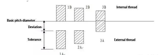
(1) For unified inch threads:
External threads have three classes: Class 1A, Class 2A, and Class 3A.
Internal threads have three classes as well: Class 1B, Class 2B, and Class 3B, all of which are clearance fits.
The higher the class number, the tighter the fit.
In English threads, only Class 1A and Class 2A have specified deviations. Class 3A has a zero deviation, and Class 1A and Class 2A have equal deviation.
The higher the class number, the lower the tolerance, as shown in the figure.
Class 1A and Class 1B have a very loose tolerance and are suitable for internal and external thread tolerance fits.
Class 2A and Class 2B are the most widely used thread tolerance grades specified for British series mechanical fasteners.
Class 3A and Class 3B have the tightest fit and are suitable for fasteners with tight tolerances, particularly for safety-critical designs.
External threads have specified fit deviations for Class 1A and Class 2A, but not for Class 3A.
The tolerance for Class 1A is 50% greater than that of Class 2A and 75% greater than that of Class 3A. For internal threads, the tolerance for Class 2B is 30% greater than that of Class 2A.
The tolerance for Class 1B is 50% greater than that of Class 2B and 75% greater than that of Class 3B.
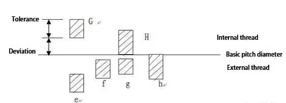
(2) The common thread grades for external metric threads are 4H, 6E, 6G, and 6H, while the common thread grades for internal threads are 6G, 6H, and 7H.
The accuracy grade of Japanese standard threads is divided into three grades: I, II, and III, with grade II being the most commonly used.
In metric threads, the basic deviation of H and h is zero, while the basic deviation of G is positive, and the basic deviation of e, f, and g is negative, as shown in the figure.
H is the most commonly used tolerance zone position for internal threads, and is generally not used for surface coating or very thin phosphating layers. The use of the basic deviation of G position is rare, and it is mainly used for thicker coatings.
The G tolerance zone is often used for plating with a 6-9um thin coating. For example, when product drawings call for 6H bolts, the threads should be plated with 6G tolerance zone.
The best thread fit combinations are H/G, H/H, or G/H. For refined fasteners such as bolts and nuts, it is recommended to use 6H/6G.
Medium accuracy grade of ordinary thread
Nut: 6H
Bolt: 6g
Medium accuracy grade of threads with thick covering
Nut: 6G
Bolt: 6e
High precision grade
Nut: 4H
Bolt: 4h, 6h
M6-P1. 0
External diameter
Effective diameter
6e
5.76-5.94
5.178-5.29
8g
5.694-5.974
5.144-5.324
6g
5.794-5.974
5.212-5.324
6h
5.82-6.00
5.238-5.350
4h
5.868-6.00
5.275-5.350
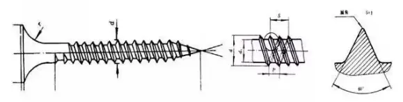
9. Common special thread
1). Self tapping thread: it is a kind of wide thread with large lead.
1. Overview of bolted connection of steel structure
Bolt connection for steel structures is a method of connecting two or more steel structure parts or components into a single unit using bolts. This type of connection is the simplest method for pre-assembling components and installing structures.
Full bolt connection of beam column joints
Bolt connection was first utilized in the installation of metal structures. However, in the late 1930s, it was gradually replaced by rivet connections and was only used as a temporary fixing method during component assembly.
The high-strength bolt connection method emerged in the 1950s. These bolts are made of medium carbon steel or medium carbon alloy steel and have a strength that is 2 to 3 times greater than that of ordinary bolts.
High-strength bolt connection has the benefits of being convenient to construct, safe, and reliable. It has been used in the manufacturing and installation of steel structures in metallurgical factories since the 1960s.
Full bolt connection of beam splicing
2. Specification of bolt
Common bolt specifications used in steel structures include M12, M16, M20, M24, and M30. The letter “M” represents the bolt symbol and the number is the nominal diameter.
Bolts are divided into 10 grades based on their performance: 3.6, 4.6, 4.8, 5.6, 5.8, 6.8, 8.8, 9.8, 10.9, and 12.9. Bolts with grades higher than 8.8 are made of low-carbon alloy steel or medium carbon steel and undergo heat treatment (quenching and tempering). These are referred to as high-strength bolts. Bolts with grades lower than 8.8 (excluding 8.8) are referred to as ordinary bolts.
The table below shows the performance grade and mechanical properties of bolts.
The bolt performance grade is composed of two parts of numbers, which respectively represent the nominal tensile strength of the bolt and the yield ratio of the material.
For example, the meaning of bolts with performance grade of 4.6 is: the number in the first part (4 in 4.6) is 1 / 100 of the nominal tensile strength (n / mm2) of bolt material, that is, fu ≥ 400N / mm2;
The number in the second part (6 in 4.6) is 10 times of the yield ratio of bolt material, that is, fy / fu = 0.6;
Product of two numbers (4) × 6 = “24”) is 1 / 10 of the nominal yield point (or yield strength) (n / mm2) of bolt material, which means fy ≥ 240n / mm2.
According to their level of manufacturing accuracy, ordinary bolts used in steel structures can be categorized into three grades: A, B, and C.
Grade B bolts are considered refined and are typically used in mechanical products, while Grade C bolts are considered rough.
Unless specified otherwise, ordinary bolts used in steel structures are typically coarse Grade C bolts with a performance grade of either 4.6 or 4.8.
The strength design value for bolted connections should be taken from Table 3.4.1-4 of the GB50017-2003 code for the design of steel structures.
Pressure bearing connection high strength butterfly bolt
Grade 8.8
400
250
Level 10.9
500
310
component
Q235 steel
one
305
405
470
Q345 steel
385
510
590
Q390 steel
400
530
615
Q420 steel
425
560
615
Table 3.4.1-5 strength design value of rivet connection (n / mm2)
Willow nail steel grade and component steel grade
Pull off nail
Shear resistance
Pressure bearing
Type I hole
Class II hole
Type I hole
Class II hole
rivet
BL2 or BL3
120
185
155
component
Q235 steel
450
365
Q345 steel
565
460
3. Classification of bolts
Bolts are known by various names such as screws, bolt nails, standard parts, fasteners, etc.
In a general sense, bolts can encompass a range of fasteners including ordinary bolts, high-strength bolts, anchor bolts, expansion bolts, chemical anchors, screws, studs, and more.
When considering bolts in a more specific manner, they can be divided into two categories: ordinary bolts and high-strength bolts.
(1) Common bolt connection
Ordinary bolts can be further divided into rough and refined bolts based on their manufacturing accuracy.
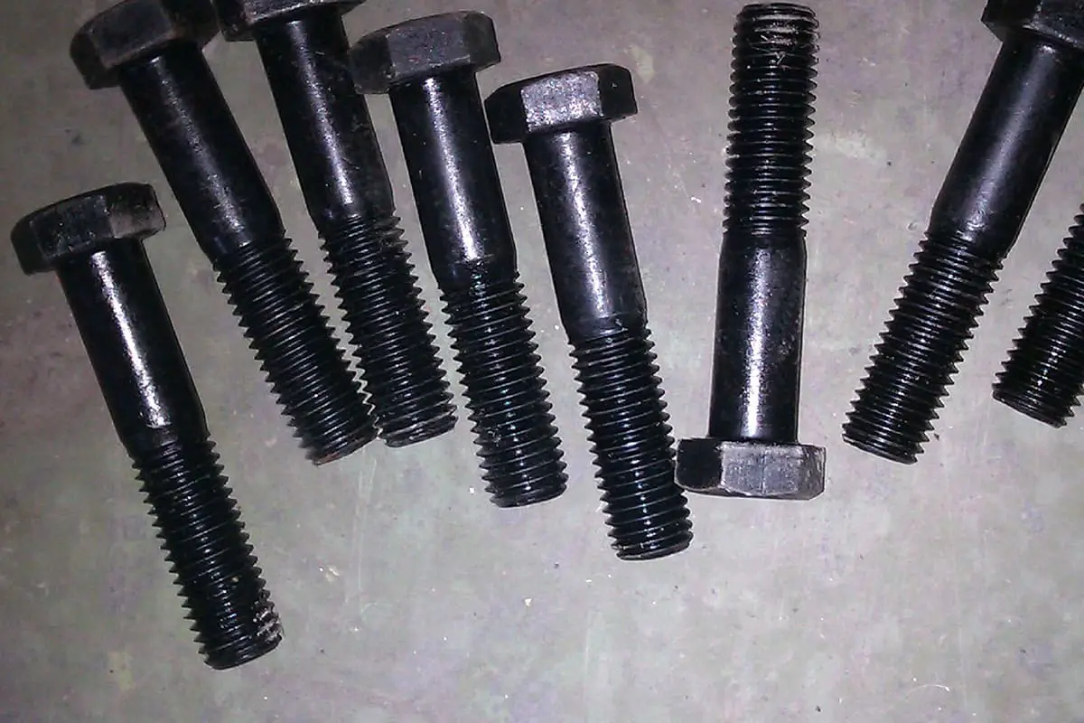
Additionally, ordinary bolts can also be classified into various types, such as hexagon head bolts, stud bolts, countersunk head bolts, and others.
The above picture shows countersunk head bolts
Rough bolt
Class C bolts are typically rough bolts made of carbon structural steel.
To ensure smooth penetration of the bolts into the screw holes, the hole diameter should be 1.0 to 2.0mm larger than the nominal diameter (d) of the bolts, resulting in a Class II hole.
The bolt hole spacing should be arranged to facilitate tightening with a wrench.
When rough bolts are used to connect the components of columns, beams, and roof trusses, a connection structure with supporting plates should be adopted.
In this scenario, the bolt is under tension and its shear force is carried by the supporting plate (as illustrated in the accompanying diagram).
The low strength grade of the materials used in rough bolts restricts its usage in structural connections. However, rough bolts are still commonly utilized in the connection of secondary beams for working platforms, wall skin beams, roof beams, supports, and hinged supports with low shear force.
The figure above depicts ordinary bolts.
Rough bolts are also frequently used in the pre-assembly of steel structures in workshops, pre-fastening of riveted components before riveting, assembly prior to high-strength bolt connection, and temporary fastening before node welding.
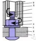
When using rough bolts as permanent fixing bolts, they should be tightened after proper alignment and measures should be taken to prevent loosening.
The figure above illustrates the double nut locking method for the column base bolt.
Refined bolt
Grades A and B bolts are considered refined bolts and typically require Class I holes. The hole diameter should be 0.3 to 0.5mm larger than the nominal diameter (d) of the bolt.
Refined bolt connections are used in some structural connections that are often disassembled and reassembled.
Refined bolts are primarily used in mechanical products and are not commonly used in building steel structures.
(2) High strength bolt connection
Bolts made of high-strength steel or requiring a high preload are referred to as high-strength bolts.
These bolts generate tension and transmit external forces through friction.
In contrast, a traditional bolt connection transmits shear force through the shear resistance of the bolt and the bearing pressure of the hole wall.
When tightening the nut, the tension is minimal and can be disregarded.
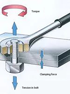
In addition to its high material strength, a high-strength bolt also applies a significant tension, resulting in extrusion pressure between the connecting components, providing a strong friction perpendicular to the screw’s direction.
Furthermore, factors such as tension, anti-slip coefficient, and steel type directly impact the bearing capacity of a high-strength bolt.
Working principle of high strength bolt
High-strength bolts are primarily classified into two categories based on their stress conditions: friction type and pressure type.
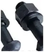
In terms of construction process, high-strength bolts are divided into two types: torsional shear high-strength bolts and large hexagonal high-strength bolts.
Torsional shear type high-strength bolt and large hexagon high-strength bolt
The friction type high-strength bolt connection transfers external force through the friction generated on the contact surface of the steel plate after the connecting plate layer is tightly adhered by the bolt tightening pressure. The component surface is sandblasted to create a red rust surface, which provides a high friction coefficient and reduces the number of connecting bolts required. The hole diameter for a friction type high-strength bolt should be 1.5 to 2.0mm larger than the nominal diameter (d) of the bolt.
In contrast, the pressure bearing high-strength bolt connection transfers stress through the combination of friction between components, shear force of the bolt’s central axis, and the bearing pressure of the component. The hole diameter for this type of bolt should be 1.0 to 1.5mm larger than the nominal diameter (d) of the bolt. Holes are drilled using a CNC drilling machine and drilling jig.
In essence, the friction type and pressure type high-strength bolts are the same bolt, with the difference being the consideration of sliding in the design. The friction surface of the friction type high-strength bolt cannot slide and the screw does not bear shear. If the friction surface slides, it is considered to have reached the design failure state, which is a relatively established and reliable technology. On the other hand, the friction surface of the pressure bearing high-strength bolt can slide and the screw also bears shear, with the final failure being similar to an ordinary bolt (bolt shear failure or steel plate compression failure).
The large hexagonal high-strength bolt is composed of a high-strength bolt, nut, and two washers, forming a high-strength bolt connection pair. During construction, the structure is temporarily fixed with rough bolts, and then high-strength bolts are installed one by one from the middle of the bolt group, starting with initial tightening, followed by re-tightening, and finally final tightening.
The figure shown above depicts large hexagonal head high-strength bolt connection pairs of varying lengths.
When installing the large hexagonal head high-strength bolt connection pair, a washer should be placed on both sides of the bolt. The initial tightening torque value should be 50% of the final tightening torque value, while the re-tightening torque value should equal the final tightening torque value.
The formula for calculating the final tightening torque value is:
TC = k * Pc * d
Where
Tc is the final tightening torque value, in n · m;
k is the torque coefficient;
Pc is the construction pretension, in kN;
d is the thread diameter of high-strength bolt, in mm.
A torque wrench should be used for tightening and should be calibrated before each use.
The torsional shear type high-strength bolt connection pair is comprised of a high-strength bolt, a nut, and a washer.
Installation principle of torsional shear high strength bolt
When installing the torsional shear type high-strength bolt connection pair, only one washer should be placed on one side of the nut.
The formula for calculating the initial tightening torque value is:
Tc = 0.065 * Pc * d
Where
Tc is the initial tightening torque value, in n · m;
Pc is the construction pretension, in kn;
d is the thread diameter of high-strength bolt, in mm.
Finally, a specialized wrench should be used to unscrew the tail plum blossom head until it breaks.
Quality inspection should focus on supervising and inspecting the construction process.
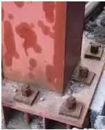
(3) Anchor bolt
An anchor bolt, also known as an anchor screw or anchor wire, is used to connect a steel structure column base to a concrete foundation. Q235 and Q345 round steel are commonly used for this purpose.
There are different types of anchor bolts, and if the diameter is greater than 24mm, an anchor plate should be used.
During installation, the anchor bolt group should be secured by the steel frame and installed along with the binding reinforcement cage before pouring the concrete. The bolt head should be exposed to the concrete surface for a specific length.
Once the concrete has reached a certain level of strength, the steel column base should be installed, and secondary grouting should be performed at the bottom of the column.
Steel frame fixed anchor bolt group
Schematic diagram of anchor bolt
The picture depicts a steel structure column base before secondary grouting, with a rubber sleeve being used to protect the top of the anchor bolt from the thread.
(4) Chemical anchor bolt
The chemical anchor bolt is a new type of fastening material that consists of a chemical agent and a metal rod. It is used to install connectors of other structures on existing concrete structures.
It can be utilized for the installation of post-embedded parts in various steel structure constructions, such as curtain walls and marble dry hanging. Additionally, it can be used for equipment installation, installing highway and bridge guardrails, reinforcing and transforming buildings, and other applications.
Screw and agent of chemical anchor bolt
The chemical anchor bolt is a new type of anchor bolt that follows the expansion anchor bolt. It is a composite component that is secured and fixed in the drilled concrete substrate through a special chemical adhesive and screw, thus achieving the anchoring of fixed parts.
The chemical anchor bolt boasts a large pull-out bearing capacity and can replace the embedded anchor bar. It is often used to address the issue of forgetting to install the embedded parts of a steel structure on the construction site after the concrete has been poured. The chemical anchor bolt can be used to correct this situation.
The construction steps of chemical anchor bolt are as follows:
In accordance with engineering design requirements, drill holes at the designated positions in the base material (such as concrete). The hole diameter, depth, and bolt diameter should be determined by professional technicians or field tests.
Drill the holes using either a percussion drill or a water drill.
Clean the dust from the drilling holes using a special air cylinder, brush, or compressed air machine. This should be repeated at least three times to ensure that there is no dust or water left in the hole.
Ensure that the bolt surface is clean, dry, and free of oil or masonry.
Check the glass tube anchor package for any abnormalities such as damage or solidification of the agent. Insert the round head of the package into the anchor hole with the head facing outwards, and push it to the bottom of the hole.
Using an electric drill and special installation fixture, insert the screw into the bottom of the hole by rotating it strongly. Impact methods should not be used.
Once the screw reaches the bottom of the hole or the marked position on the bolt, stop rotating immediately, remove the installation fixture, and avoid disturbing the gel until it has completely cured. Over-rotating may lead to a loss of glue and affect anchoring force.
(The rotation time should not exceed 30 seconds, the rotation speed should be between 300 to 750 rpm, the bolt propulsion speed should be about 2 cm/s, and impact methods are not allowed).
(5) Expansion bolt
The function of an expansion bolt is similar to that of a chemical anchor bolt, and it is used for anchoring applications with less stress.
Expansion bolts of different specifications
Expansion bolts should not be used on parts with cracks or on parts that are prone to cracking in concrete structures.
When designing main load-bearing structures, important pipelines, high-speed operations, bearing impact loads, and large vibrations, the expansion bolts should be selected based on the calculated design tensile force and design shear force.
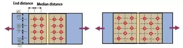
4. Arrangement and construction requirements of bolts
The arrangement of bolts can be divided into two categories: parallel and staggered.
Parallel arrangement – this arrangement is simple, neat, and compact. The size of the connecting plate used is small, but it results in a significant weakening of the component section.
Staggered arrangement – this arrangement is not as compact, but the size of the connecting plate used is larger, resulting in a smaller weakening of the member section.
Stress requirements
Vertical Stress Direction: To prevent stress concentration in bolts and excessive weakening of the section, as well as to reduce the bearing capacity, the edge distance and end distance of bolts should not be too small.
Direction of Force Action: To prevent the plate from breaking or shearing, the end distance should not be too small.
For Compression Members: To prevent buckling of connecting plates, the middle distance should not be too large.
Construction Requirements:
The edge distance and middle distance of bolts should not be too large to avoid loose fitting between plates, moisture intrusion, and corrosion of steel.
To facilitate the tightening of the nut with a wrench, the bolt pitch should not be less than 3 times the diameter of the bolt.
According to these requirements, the allowable spacing of bolts and relevant design values are specified in the GB50017-2017 code for the design of steel structures.
Table 8.3.4 maximum and minimum allowable distances of bolts or rivets
name
Position and direction
Maximum allowable distance (whichever is smaller)
Minimum allowable distance
Center spacing
Outer row (vertical or along the direction of internal force)
Rolling edge, automatic gas cutting or sawing edge
High strength bolt
Other bolts or nails
1.2d
Note:
1. d0 Is the hole diameter of the bolt or nail, and t is the thickness of the outer sheet.
2. The maximum distance between the steel plate edge and the bolt or rivet connected to the rigid member (such as angle steel, channel steel, etc.) can be adopted according to the value of the middle row.
As the founder of MachineMFG, I have dedicated over a decade of my career to the metalworking industry. My extensive experience has allowed me to become an expert in the fields of sheet metal fabrication, machining, mechanical engineering, and machine tools for metals. I am constantly thinking, reading, and writing about these subjects, constantly striving to stay at the forefront of my field. Let my knowledge and expertise be an asset to your business.
What if the future of engineering isn't just about innovative designs, but groundbreaking materials? From optical fibers revolutionizing data transmission to superconductive materials enhancing energy efficiency, the latest advancements in…
Have you ever thought about the hidden strength behind the bolts holding our world together? This article explores the fascinating world of bolt weights and strength grades, revealing how these…
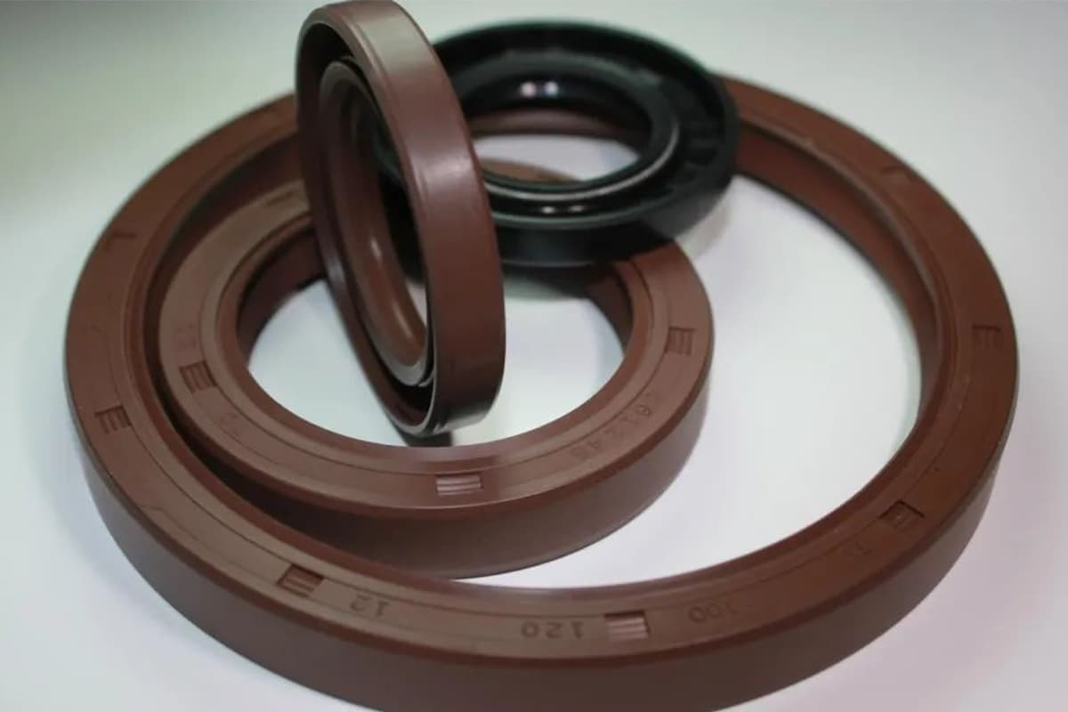
How do you keep crucial lubricants from leaking and causing damage in machinery? Skeleton oil seals might just be the unsung heroes of industrial maintenance. These seals play a vital…
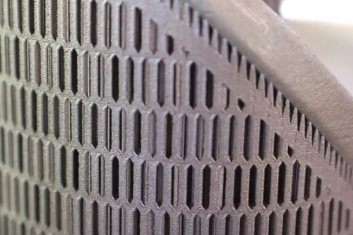
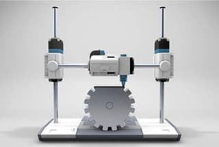
What makes intricate designs possible in 3D printing? The answer lies in support structures. This article explores the necessity, types, and design strategies of support structures that prevent part deformation…
1. What are the factors affecting the fatigue strength of bolts? There are various factors that can impact the fatigue strength of a connection, including the material used, structural design,…
What makes a material suitable for a specific engineering application? The answer lies in understanding its properties. This article covers 11 essential material properties, such as mechanical strength, impact toughness,…
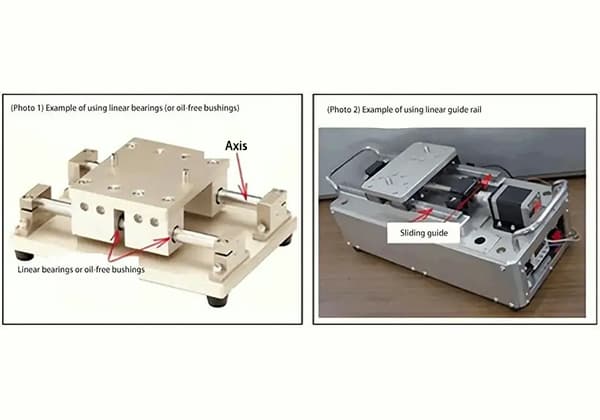
Have you ever wondered what the key to smooth, precise motion is in machines? Linear bearings are the unsung heroes behind countless automated systems, enabling effortless transfer, handling, positioning, and…
Imagine creating anything you want, layer by layer, right at your desk. Welcome to the world of 3D printing! This revolutionary technology, also known as additive manufacturing, builds objects by…
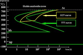
How does the cooling rate affect the microstructure of steel? The C-curve in heat treatment reveals the fascinating transformation of carbon steel's microstructure during cooling. This article delves into the…