Sheet Metal Joining Process: The Ultimate Guide
Have you ever wondered how sheet metal parts are joined together to create complex structures? In this blog post, we'll explore the fascinating world of sheet metal joining techniques. As…
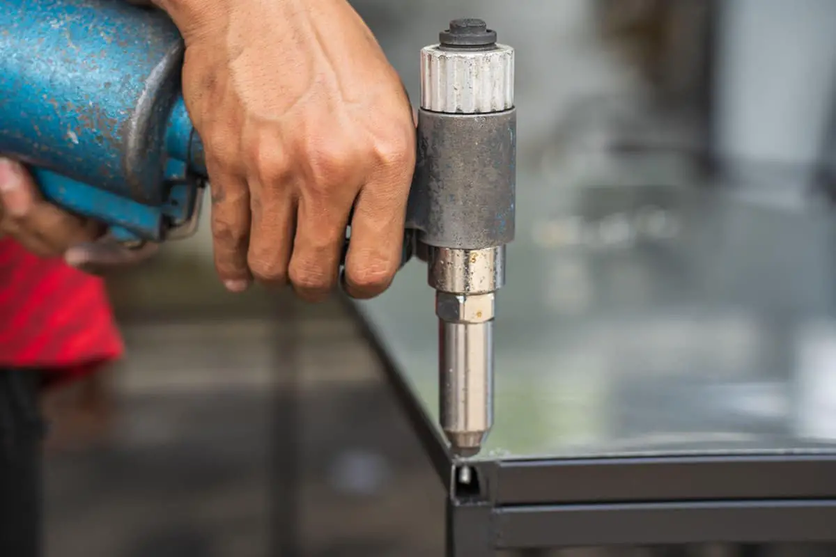
How do you ensure the reliability of sheet metal connections in your projects? Understanding the various methods of threaded connections and riveting is essential. This article delves into the principles of selecting rivets, different types of threaded fasteners, and the processes involved in press, swell, and pull riveting. By exploring these techniques, you’ll learn how to choose the best methods for your specific applications, ensuring strong, durable connections in your sheet metal work.
Threaded connections, a widely used and detachable fixing method, are simple in structure, reliable, and easy to assemble and disassemble. They are one of the most commonly used and broadest connection methods in sheet metal product structures, possessing irreplaceable advantages.
Common riveting methods for threaded fasteners in sheet metal parts include press riveting, swell riveting, and pull riveting.
1) Pay attention to the outer dimensions of the rivet to avoid interference.
2) Depending on the riveting method of the rivet, consider the direction of force applied to the rivet during assembly to avoid pull-out incidents.
3) The length of the rivet section should be slightly less than the thickness of the sheet, determined based on the thickness of the sheet.
4) When choosing rivets, consider the riveting method and leave space for the riveting operation.
5) Since the base plate deforms during press riveting and the fitting deforms during swell riveting, for stainless steel or materials with higher hardness, choose the swell riveting method.
6) For base plates less than 1mm thick, press riveting should be avoided. If there are special requirements, use the swell riveting method.
7) Swell rivets are more secure than press rivets and should be used unless there are special requirements.
8) For base plates thicker than 3.0mm, hexagon head press rivets should be avoided. Use round head press rivets to ensure the flatness after press riveting.
9) When choosing press rivets, note: M5 and below round head press rivets are suitable for riveting sheets with a thickness between 1.0~2.0mm; M6 round head press rivets are suitable for riveting sheets with a thickness between 2.0~2.5mm; M8 round head press rivets are suitable for riveting sheets thicker than 2.5mm.
Common structural forms of riveted components include press rivet nut columns, press rivet nuts (studs), expanding rivet nuts (studs), pull rivet nuts, floating press rivet nuts, and more.
(1) Press Rivet Nut Column
Also known as press rivet stud or nut column, it is a type of fastener widely used in sheet metal, thin plates, chassis, and cabinets. There is no specific national standard for press rivet nut columns. The base of the press rivet nut column is hexagonal, and the other end is cylindrical, with a groove in the middle of the hexagonal base and the cylinder.
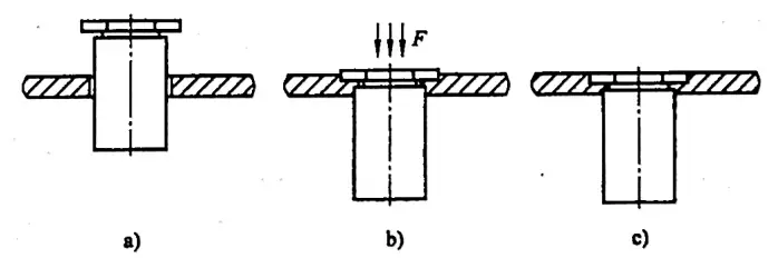
Press riveting is carried out on a special press machine using a mold, applying a certain amount of pressure to press the hexagonal head into a pre-set hole in the plate (the diameter of the pre-set hole is generally slightly larger than the outer diameter of the press rivet nut column’s cylinder).
This causes plastic deformation around the hole, with the deformed part being squeezed into the groove of the press rivet nut column, thereby riveting the press rivet nut column tightly on the plate. This type of riveting usually requires the hardness of the press rivet nut column to be greater than the hardness of the thin plate.
Ordinary low carbon steel plates (hardness less than 70HRB), aluminum alloy plates, copper plates, etc. are all suitable for press-fitting press rivet nut columns. For stainless steel plates and high carbon steel plates, due to their hard material, special high-strength press rivet nut columns are not only expensive, but also difficult to press, unreliable in riveting, and easy to fall off.
To ensure the reliability of riveting, it is often necessary to spot weld 2-3 points on the side of the press rivet nut column, so the process is poor. If the product must be riveted with stainless steel and high carbon steel plates, the hardness of the steel plate must be less than 80HRB.
Therefore, sheet metal parts with press rivet nut columns should avoid using stainless steel plates. The same applies to press rivet screws and press rivet nuts, which are not suitable for use on stainless steel plates. The process of press riveting the press rivet nut column is shown in Figure 9-1.
(2) Press Rivet Nut
Press rivet nuts are also a type of fastener widely used in sheet metal, thin plates, machine cases, and cabinets.
There is currently no specific national standard for press rivet nuts. They differ from press rivet nut columns by having added serrated steps and inverted heads, appearing circular in shape. The riveting principle of the press rivet nut is the same as that of the press rivet nut column. The riveting process of the press rivet nut is shown in Figure 9-2.

(3) Swell Rivet Nut
The swell rivet nut is a type of fastener used in sheet metal, thin plates, machine cases, and cabinets. Currently, there are no specific national standards for swell rivet nuts. There are two types of swell rivet nuts: hexagonal and round.
Before installing the swell rivet nut, a bottom hole must be pre-set on the sheet metal. Then, the swell rivet nut is inserted into the hole. On a special press machine, using a mold (with a taper on the upper mold head), a certain amount of pressure is applied to expand part of the swell rivet nut’s handle (causing some of the material to undergo plastic deformation).
This forms a certain taper, causing the swell rivet nut to tightly fit with the sheet metal, thereby fastening the swell rivet nut onto the thin plate, completing the riveting. The swell rivet nut generally doesn’t need to be hardened to ensure its toughness, ensuring that it can be tightened without cracking.
The riveting process is relatively simple, but because the connection between the swell rivet nut and the sheet metal is a deformed connection in the circumferential direction, it can withstand a larger push-out force, but the torque it can bear is smaller.
To compensate for this shortcoming, it is recommended to use hexagonal swell rivet nuts with reverse buckles or round swell rivet nuts with serrations. The bite between the reverse buckle or serration and the sheet metal increases the torque that the swell rivet nut can withstand. The process of swelling the rivet nut is shown in Figure 9-3.

(4) Rivet Nut
Also known as riveted nut or clinch cap, it is commonly used for fastening various sheet metal parts. Riveting refers to the process where the rivet nut, under the influence of external pull force, locally undergoes plastic expansion deformation (usually at specially designed locations) to clamp the sheet, thereby achieving reliable connection.
The method of riveting process involves the use of a specialized riveting gun. The riveting gun drives the bolt in its head to rotate through the engagement with the internal thread of the rivet nut, leading to the corresponding linear motion of the rivet nut and causing the thin-walled area of the rivet nut to expand and deform until it clamps the sheet.
By clamping the sheet through local deformation, the rivet nut can withstand a large push-out force and a certain amount of torque. Sometimes, to ensure the ability to withstand a large torque, hexagonal or serrated rivet nuts may be employed. The advantage of rivet nuts is single-sided construction, unaffected by product closure. The riveting process of the rivet nut is shown in Figure 9-4.

1) Common materials for rivet nuts include steel, aluminum alloy, and stainless steel. Varieties include flat-head rivet nuts (GB/T17880.1-1999), countersunk rivet nuts (GB/T17880.2-1999), small countersunk rivet nuts (GB/T17880.3-1999), 120° small countersunk rivet nuts (GB/T17880.4-1999), and hexagonal flat-head rivet nuts (GB/T17880.5-1999).
2) The use of rivet nuts: if a product requires the nut to be mounted externally while the internal space is narrow, preventing the riveting machine’s head from entering for riveting, and methods such as flanging and tapping cannot meet the strength requirements, then neither pressing nor expanding riveting will work, necessitating the use of pull riveting. Rivet nuts are suitable for connecting sheet metal parts with a thickness between 0.5 and 6m.
(5) Floating rivet nuts
Sheet metal products such as computer cases and cabinets are typically composed of many parts. Some sheet metal parts or components, due to the complex overall structure of the cases or cabinets and the large cumulative assembly size errors, result in significant deviations in the assembly position of the rivet nuts, making assembly of other parts difficult and, in some cases, impossible.
Therefore, using floating rivet nuts in certain positions instead of other types of rivet nuts can significantly improve this situation. The riveting process of the floating rivet nut is shown in Figure 9-5. There are no national standards for floating rivet nuts at present, only industry standards. When choosing to use them, the pre-set hole size and installation space should be determined according to the manufacturer’s product samples.

(6) Dimensions of the bottom hole of the riveted part and applicable sheet thickness
1) For the diameter of the bottom hole of the press-riveted nut pillar, refer to Table 9-1.
Table 9-1 Diameter of the Bottom Hole of the Press-Riveted Nut Pillar (Unit: mm)
| Thread Specifications | Codename | Diameter d of the base hole |
| M3×0.5 | (B)S0(0)(S)-M3-H | φ4.2 |
| M3×0.5 | (B)S0(0)(S)-3.5M3-H | φ5.4 |
| M4×0.7 | (B)S0(0)(S)-M4-H | φ6.0 |
| M4×0.7 | (B)S0(0)(S)-3.5M4-H | φ7.2 |
| M5 ×0.8 | (B)S0(0)(S)-M5-H | φ7.2 |
| M6×1.0 | (B)S0(0)(S)-M6-H | φ8.7 |
Note: S0 S0S denotes through-hole non-threaded press rivet nut columns; S00 S00S denotes through-hole threaded press rivet nut columns. Adding a B before the term indicates a blind hole; adding an S at the end means the material is stainless steel, and without an S, it’s steel. H stands for the height of the nut column.
2) Refer to Table 9-2 for the diameter of the bottom hole of the press-riveted nut.
Table 9-2: Diameter of the Bottom Hole of the Press-Riveted Nut (Unit: mm)
| Thread Specifications | Codename | Diameter d of the base hole |
| M2x0.4 | S(CLS)-M2-A(0,1,2) | φ4.2 |
| M2. 5 ×0.45 | S(CLS)-M2.5-A(0,1,2) | φ4.2 |
| M3x0.5 | S(CLS)-M3-A(0,1,2) | φ4.2 |
| M4x0.7 | S(CLS)-M4-A(0,1,2) | φ5.4 |
| M5×0.8 | S(CLS)-M5-A(0,1,2) | φ6.4 |
| M6×1.0 | S(CLS)-M6-A(0,1,2) | φ8.7 |
Post: CLS signifies a rivet nut made of stainless steel; S represents a rivet nut made of steel; A (handle code) indicates the applicable thickness code for the rivet nut (0 indicates a thickness of 0.8-1.2mm, 1 indicates a thickness of 1-1.5mm, 2 indicates a thickness of 1.5~2.5mm).
3) Refer to Table 9-3 for the bottom hole diameter of the embedded nut.
Table 9-3 Diameter of bottom hole for embedded nut (Unit: mm)
| Thread Specifications | Codename | Diameter d of the base hole |
| M2x0.4 | F(S)-M2-A | φ4.3 |
| M2.5×0.45 | F(S)-M2.5-A | φ4.3 |
| M3x0.5 | F(S)-M3-A | φ4.3 |
| M4x0.7 | F(S)-M4-A | φ$7.4 |
| M5x0.8 | F(S)-M5-A | φ7.9 |
| M6x1.0 | F(S)-M6-A | φ8.7 |
Note: “F” indicates a press-in nut; “S” signifies that the material is bronze; “A” (handle code) represents the thickness code for the applicable plate for the press-in nut.
4) Refer to Table 9-4 for the suitable plate thickness for the press-in nut.
Table 9-4: Applicable Plate Thickness for Press-in Nut (Unit: mm)
| Handle Code A | Thread Specifications | |||||
| M2 | M2.5 | M3 | M4 | M5 | M6 | |
| 1 | 1.5-2.3 | 1.5~2.3 | 1.5-2.3 | 1.5-2.3 | 1.5-2.3 | |
| 2 | 2.3-3.2 | 2.3-3.2 | 2.3-3.2 | 2.3-3.2 | 2.3-3.2 | |
| 3 | 3.2-3.9 | |||||
| 4 | 4~4.7 | |||||
| 5 | >4.7 | |||||
5) For the bottom hole diameter of the swage nut, refer to Table 9-5.
Table 9-5: Swage Nut Bottom Hole Diameter (Unit: mm)
| Thread Specifications | Codename | Diameter d of the base hole |
| M2.5×0.45 | Z-(S)-M2.5-A | φ5.0/Counterboring φ5.5×90° |
| M3x0.5 | Z-(S)-M3-A | 5.0/Counterboring φ5.5×90° |
| M4x0.7 | Z-(S)-M4-A | φ6.0/Counterboring φ7.0×90° |
| M5×0.8 | Z-(S)-M5-A | φ8.0/Counterboring φ9.0×90° |
| M6x1.0 | Z-(S)-M6-A | φ9.0/Counterboring φ10×90° |
| M8×1.25 | Z-(S)-M8-A | φ11/Counterboring φ12×90° |
Note: The addition of ‘S’ signifies that the material is stainless steel, whereas the absence of ‘S’ indicates that the material is steel. ‘A’ (handle code) represents the code for the applicable sheet thickness of the rivet nut.
6) The applicable sheet thickness for round expansion rivet nuts is shown in Table 9-6.
Table 9-6: Applicable Sheet Thickness for Round Expansion Rivet Nuts (Unit: mm)
| Handle Code A | Thread Specifications | |||||
| M3 | M4 | M5 | M6 | M8 | M10 | |
| 1.2 | 1.2 | 1.2 | ||||
| 1.5 | 1.5 | 1.5 | ||||
| 2.0 | 2.0 | 2.0 | 2.0 | 2.0 | 2.0 | 2.0 |
| 3.0 | 3.0 | 3.0 | 3.0 | 3.0 | ||
7) The applicable sheet thickness for hexagonal swage rivet nuts is shown in Table 9-7.
Table 9-7 Hexagonal swage rivet nut applicable sheet thickness (Unit: mm)
| Handle Code A | Thread Specifications | |||||
| M3 | M4 | M5 | M6 | M8 | M10 | |
| 1.5 | 1.5 | 1.5 | ||||
| 2.0 | 2.0 | 2.0 | 2.0 | |||
| 3.0 | 3.0 | 3.0 | 3.0 | 3.0 | ||
| 4.0 | 4.0 | 4.0 | 4.0 | 4.0 | ||
| 5.0 | 5.0 | 5.0 | 5.0 | |||
| 6.0 | 6.0 | 6.0 | ||||
Note: Hexagon swage rivet nuts are primarily used for connections involving copper base plates.
8) The diameter of the bottom hole of the press riveting screw can be found in Table 9-8.
Table 9-8: Diameter of the bottom hole of the press riveting screw
(Unit: mm)
| Thread Specifications | Codename | Diameter d of the base hole |
| M2.5×0.45 | FH(S)-2.5-L | φ2.5 |
| M3x0.5 | FH(S)-M3-L | φ3 |
| M3x0.5 | NFH(S)-M3-L | φ4.8 |
| M4x0.7 | FH(S)-M4-L | Φ4 |
| M4x0.7 | NFH(S)-M4-L | φ4.8 |
| M5 x0. 8 | FH(S)-M5-L | φ5 |
| M5 x0.8 | NFH(S)-M5-L | φ6.8 |
| M6 ×1.0 | FH(S)-M6-L | φ6 |
| M6 ×1.0 | NFH(S)-M6-L | φ6.8 |
Note: ‘S’ indicates that the material is stainless copper, while no ‘S’ implies that the material is steel. ‘FH’ represents a round head, ‘NFH’ denotes a hexagonal head, and ‘L’ signifies the total length of the screw.
9) For the diameter of the bottom hole of the pull rivet nut and the applicable plate thickness, please refer to the national standard: Flat head rivet nut (GB/T17880.1-1999), Countersunk rivet nut (CB/T17880.2-1999), Small countersunk rivet nut (GB/T17880.3-199), 120° small countersunk rivet nut (GB/T17880.4-1999), Flat head hexagonal rivet nut (GB/T17880.5-1999).
(7) The minimum distance from the center of the bottom hole of the riveted part to the edge of the base plate.
1) The recommended minimum distance from the center of the bottom hole of the commonly used press rivet nut post to the edge of the base plate is as shown in Table 9-9.
Table 9-9 Recommended minimum distance from the center of the bottom hole of the commonly used press rivet nut post to the edge of the base plate (unit: mm).
| Thread Specifications | Codename | Recommended minimum distance from the center of the bottom hole to the edge of the base plate. |
| M3x0.5 | (B)S0(0)(S)-3.5M3-H | 6.8 |
| M4x0.7 | (B)S0(0)(S)-M4-H | 8.0 |
| M5x0.8 | (B)S0(0)(S)-M5-H | 8.0 |
| M6x1.0 | (B)S0(0)(S)-M6-H | 10 |
2) The recommended minimum distance from the center of the commonly used rivet nut bottom hole to the edge of the base plate is shown in Table 9-10.
Table 9-10 Recommended minimum height from the center of the commonly used rivet nut bottom hole to the edge of the base plate (units: mm)
| Thread Specifications | Codename | Recommended minimum distance from the center of the bottom hole to the edge of the base plate. |
| M3x0.5 | S(CLS)-M3-A(0,1,2) | 4.8 |
| M4x0.7 | S(CLS)-M4-A(1,2) | 6.9 |
| M5x0.8 | S(CLS)-M5-A(1,2) | 7.1 |
| M6x1.0 | S(CLS)-M6-A(1,2) | 8.6 |
| M8×1.0 | S(CLS)-M8-2 | 9.7 |
| M10 x1. 5 | S(CLS)-M10-2 | 13.5 |
3) The recommended minimum distance from the center of the commonly used embedded nut bottom hole to the edge of the base plate is given in Table 9-11.
Table 9-11 Recommended minimum distance from the center of the commonly used embedded nut bottom hole to the edge of the base plate (Unit: mm)
| Thread Specifications | Codename | Recommended minimum distance from the center of the bottom hole to the edge of the base plate. |
| M3x0.5 | F(S)-M3-1.5 | 6 |
| M4x0.7 | F(S)-M4-2.5 | 6 |
| M5x0.8 | F(S)-M5-2.5 | 7.2 |
4) The recommended minimum distance from the center of the bottom hole of the commonly used round expansion rivet nut to the edge of the base plate is shown in Table 9-12.
Table 9-12 Recommended minimum distance from the center of the bottom hole of the commonly used round expansion rivet nut to the edge of the base plate (Unit: mm)
| Handle Code A | Thread Specifications | ||||
| M3 | M4 | M5 | M6 | M8 | |
| 1.2 | 4.8 | 6.9 | |||
| 1.5 | 4.8 | 6.9 | |||
| 2.0 | 4.8 | 6.9 | 7.1 | 8.6 | 9.7 |
| 3.0 | 7.1 | 8.6 | 9.7 | ||
5) The recommended minimum distance from the center of the base hole of the commonly used hexagonal swell rivet nut to the edge of the substrate is shown in Table 9-13.
Table 9-13 Recommended minimum distance from the center of the base hole of the commonly used hexagonal swell rivet nut to the edge of the substrate (Unit: mm)
| Handle Code A | Thread Specifications | |||||
| M4 | M5 | M6 | M8 | M10 | M12 | |
| 1.5 | 6.9 | |||||
| 2.0 | 6.9 | 7.1 | ||||
| 3.0 | 6.9 | 7.1 | 8.6 | 9.7 | ||
| 4.0 | 7.1 | 8.6 | 9.7 | 13.5 | 15 | |
| 5.0 | 8.6 | 9.7 | 13.5 | 15 | ||
| 6.0 | 9.7 | 13.5 | 15 | |||
6) The recommended minimum distance from the center of the common rivet screw bottom hole to the edge of the base plate is shown in Table 9-14.
Table 9-14 Recommended minimum distance from the center of the common rivet screw bottom hole to the edge of the base plate (Unit: mm)
| Thread Specifications | Code Name | Recommended minimum distance from the center of the (round head) bottom hole to the edge of the base plate. |
| M3 x0.5 | FH(S)-M3-L | 5.6 |
| M4x0.7 | FH(S)-M4-L | 7.2 |
| M5x0.8 | FH(S)-M5-L | 7.2 |
| M6x1.0 | FH(S)-M6-L | 7.9 |
(8) Factors Affecting the Quality of Rivet Assembly
There are several factors that influence the quality of rivet assembly, including the properties of the base material, the diameter of the bottom hole, and the riveting method.
1) Base Material Properties: When the hardness of the base material is appropriate, the quality of the riveting and the load-bearing capacity of the riveted parts are optimal.
2) Bottom Hole Diameter: The size of the bottom hole directly affects the quality of the riveted assembly. A larger bottom hole results in a larger gap between the base material and the riveted parts. The effects of this gap on different riveting methods are as follows:
i) Impact on Compression Riveting: The base material cannot deform enough to fill the groove on the riveted part, resulting in insufficient shear force and directly affecting the push resistance of the compression rivet nut (or rivet).
ii) Impact on Expansion Riveting: If the bottom hole is too large, the squeezing force generated by plastic deformation during riveting decreases, directly affecting the push and torsional resistance of the expansion rivet.
iii) Impact on Pull Riveting: If the bottom hole is too large, the effective friction between the two parts decreases after plastic deformation, affecting the quality of riveting.
Although a smaller hole can increase the load-bearing capacity of the rivet to some extent, it can lead to poor aesthetic quality, high riveting force, inconvenience in installation, deformation of the base plate, and decreased production efficiency and riveting quality.
3) Distance from the Center of the Bottom Hole to the Edge of the Base Material: If this distance is too short, it can cause the base material to deform and affect the quality of riveting.
(9) Principles of Rivet Assembly Process
When preparing process cards for sheet metal parts with riveted components, special attention should be paid not only to the rational arrangement of the riveting process, but also to the position of the rivet screw or rivet nut.
Different positions bear different loads and have different process requirements. Therefore, the structure of the riveted parts and the riveting process should be adapted to the riveting position. Improper selection can reduce the load range of the rivet screw or rivet nut, leading to riveting failure. The general principles for riveting rivet screws and rivet nuts are as follows:
1) Do not rivet steel or stainless steel rivet screws and rivet nuts before anodizing or surface treating aluminum plates.
2) The number of compression rivet screws or rivet nuts riveted on the same line should be reasonable. If there are too many, the squeezed material has nowhere to flow, which can cause great stress, bending the workpiece into an arc.
3) It is preferable to coat the surface of the parts before riveting the rivet screws and rivet nuts.
4) After riveting, M5, M6, M8, and M10 rivet nuts generally need to be spot welded to increase their strength. Larger nuts require greater strength and can be arc welded. For M4 (including M4) and below, it is best to use expansion rivet nuts.
5) When riveting nuts on a bend edge, to ensure the quality of the nut riveting, note the following:
① The distance from the rivet hole edge to the bend edge must exceed the deformation zone of the bend.
② The distance L from the center of the riveted nut to the inner side of the bend edge should be greater than the sum of the outer cylinder radius of the riveted nut and the inner bend radius, i.e., L>D/2+r.
6) For substrates less than 1mm, the reliability of press riveting is poor, and therefore, not recommended. If there are special requirements, it can be changed to swell riveting, and 2-3 points should be reinforced with argon arc welding spot welding (or spot punching 2-3 points) on a surface that does not affect the threads.
Projection weld nuts, also known as spot weld nuts, are widely used in sheet metal products. However, during actual application, issues often arise due to an improperly designed hole diameter, resulting in the inability to accurately position the projection weld nut.
National standards include two types of projection weld nuts: square weld nuts (GB13680-1992) and hexagonal weld nuts (GB13681-1992). Square weld nuts have a rough positioning, not only resulting in significant positioning errors, but often requiring thread chasing after welding.
In contrast, hexagonal weld nuts have a self-positioning structure, offering higher accuracy and more convenient welding operations. Therefore, it is advisable to use hexagonal weld nuts.
A schematic diagram of the welding of a hexagonal weld nut to a base plate is shown in Figure 9-6. Recommended values for the base plate hole diameter D and plate thickness t are presented in Table 9-15.
Figure 9-6: Schematic Diagram of Hexagonal Weld Nut Welded to Base Plate
Table 9-15: Recommended Values for Base Plate Hole Diameter D and Plate Thickness t
(Unit: mm)
| Thread Specifications | D | t | ||
| M4 | 6+0.075 | 0.75~3 | ||
| M5 | 7+0.09 | 0.9~3.5 | ||
| M6 | 8+0.09 | 0.9~4 | ||
| M8 | M8×1 | 10.5+0.11 | 1-4.5 | |
| M10 | M10×1 | M10x1.25 | 12.5+0.11 | 1.25-5 |
| M12 | M12x1.5 | M12×1.25 | 14.8+0.11 | 1.5-5 |
| M14 | M14 x1.5 | 16.8+0.11 | 2~6 | |
| M16 | M16×1.5 | 18.8+0.13 | 2~6 | |
Flanging and tapping, also known as hole-pulling and tapping, is primarily used on sheet metal parts to establish connections between them. Because the base of the sheet metal part is thin, directly tapping it would result in too short a thread, which can easily slip.
Therefore, a bottom hole is first punched on the sheet metal part (determined by the thread specifications). Then, using a dedicated flanging (hole-pulling) mold on a press machine, a vertical edge is pulled out (the pull-out height is determined by thread specifications and plate thickness). Finally, the thread is tapped, achieving the purpose of increasing the effective thread length.
Swelled rivet nuts, pressed rivet nuts, pull rivet nuts, and flanging and tapping each have their advantages and disadvantages. Their performance comparison can be seen in Table 9-16.
Table 9-16 Performance Comparison of Swelled Rivet Nuts, Pressed Rivet Nuts, Pull Rivet Nuts, and Flanging and Tapping
| Connection Method | Swage nut | Press-in nut. | Riveted Nut | Flanging and Threading |
| Machinability | Good | Good | Good | Average |
| Substrate Material | Stainless steel rivets tend to fall off easily | Stainless steel riveting is poor, requiring the use of specially made press-in nuts and spot welding. | Good | Thin plates and soft copper and aluminum materials are prone to thread slippage. |
| Accuracy | Good | Good | Good | Average |
| Durability | Good | Good | Good | The quality of copper and aluminum materials is subpar, and other materials with more than three threads are preferable. |
| Cost | High | High. | Average | Low |
| Quality | Good | Good | Good | Average |

As the founder of MachineMFG, I have dedicated over a decade of my career to the metalworking industry. My extensive experience has allowed me to become an expert in the fields of sheet metal fabrication, machining, mechanical engineering, and machine tools for metals. I am constantly thinking, reading, and writing about these subjects, constantly striving to stay at the forefront of my field. Let my knowledge and expertise be an asset to your business.